patent · US4648801
Wind turbines
10 March 1987
Page 1 — bibliographic record
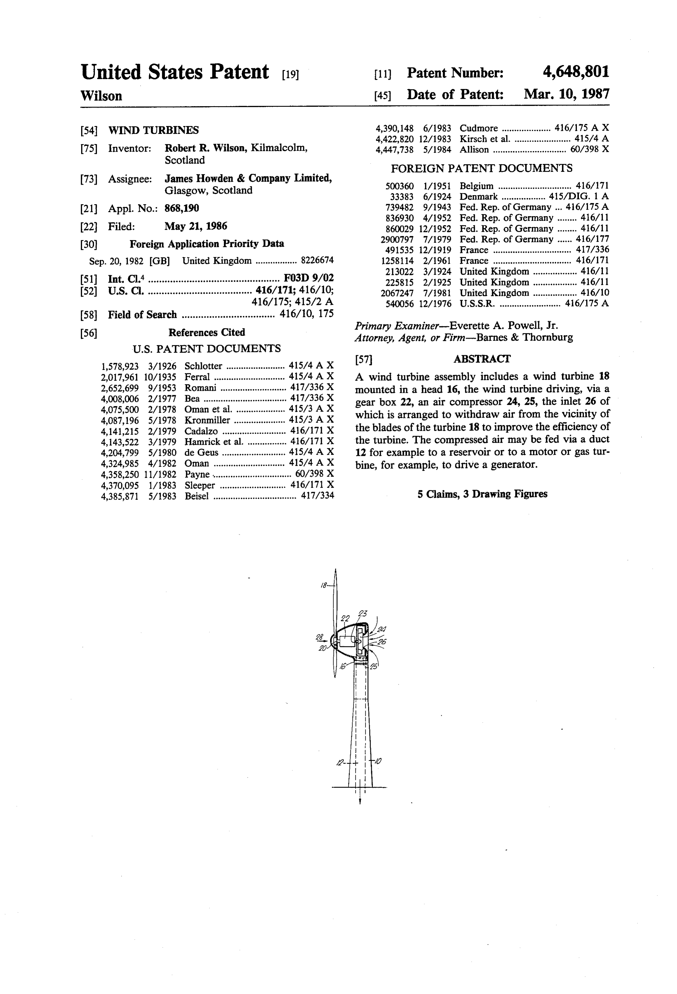
United States Patent (19) 11) Patent Number: 4,648,801 Wilson (45) Date of Patent: Mar. 10, 1987 54 WINDTURBINES 4,390,148 6/1983 Cudmore .................... 416/175 A X 4,422,820 12/1983 Kirsch et al. ....................... 41.5/4 A 75 Inventor: Robert R. Wilson, Kilmalcolm, 4,447,738 5/1984 Allison .............................. 60/398 X Scotland
FOREIGN PATENT DOCUMENTS
73) Assignee: James Howden & Company Limited, 500360 1/1951 Belgium .............................. 416/171 Glasgow, Scotland 33383 6/1924 Denmark .................. 415ADIG. 1 A (21) Appl. No.: 868,190 739482 9/1943 Fed. Rep. of Germany ... 416/175A
22 Filed: May 21, 1986 860029 12/1952 Fed. Rep. of Germany ........ 416/11 30 Foreign Application Priority Data 2900797 7/1979 Fed. Rep. of Germany ...... 416/177 491535 12/1919 France ................................ 417/336
Sep. 20, 1982 GB) United Kingdom ................. 8226674 1258114 2/1961 France ................ 416/171
51) Int. Cl."................................................ FO3D 9/02 225815 2/1925 United Kingdom ... ... 416/11 52 U.S. C. ...................................... 416/171; 416/10; 2067247 7/1981 United Kingdom ... ... 416/10 416/175; 415/2 A 54.0056 12/1976 U.S.S.R. ......................... 416/175 A 58 Field of Search .................................. 416/10, 175 (56) References Cited Primary Examiner-Everette A. Powell, Jr. Attorney, Agent, or Firm-Barnes & Thornburg
2,017,961 10/1935 Ferral ... ... 41.5/4 AX A wind turbine assembly includes a wind turbine 18 2,652,699 9/1953 Romani. ... 417/336 X mounted in a head 16, the wind turbine driving, via a 4,008,006 2/1977 Bea ............ ... 417/336 X gear box 22, an air compressor 24, 25, the inlet 26 of 4,075,500 2/1978 Oman et al. ... ... 415/3A X which is arranged to withdraw air from the vicinity of 4,087,196 5/1978 Kronmiller ... ... 415/3 AX 4,141,215 2/1979 Cadalzo ........ ... 416/171 X the blades of the turbine 18 to improve the efficiency of 4,143,522 3/1979 Hamrick et al. .. ... 416/171 X the turbine. The compressed air may be fed via a duct 4,204,799 5/1980 de Geus ........ ... 41.5/4A X 12 for example to a reservoir or to a motor or gas tur 4,324,985 4/1982 Oman .... ... 41.5/4 AX bine, for example, to drive a generator. 4,358,250 11/1982 Payne ................................ 60/398 X 4,370,095 1/1983 Sleeper. ... 416/17 X 4,385,871 5/1983 Beisel .................................. 417/334 5 Clains, 3 Drawing Figures
Page 2
Drawing sheet — no readable text.
Page 3
Drawing sheet — no readable text.
Page 4
While the air compressor may take any form, it is
WNDTURBNES preferably a fan, for example of the centrifugal type. The direction of rotation of the fan is preferably oppo
DESCRIPTION site to the direction of rotation of the wind turbine rotor The present invention relates to wind turbines and to 5 and this may be achieved by gearing which preferably also increases the speed of the fan significantly relative arrangements employing wind turbines.
Wind turbines or windmills usually apply the wind to the speed of the wind turbine rotor. It will be appre power directly to the particular task for which they are ciated that the air downstream of the wind turbine rotor will have not only an axial component of movement, intended. 10 but also a rotational or swirl component. If the direction Traditionally windmills were used for grinding corn of rotation of the compressor fan is chosen to be oppo and the drive from the windmill is taken via a suitable gearing to the grinding stones. Wind turbines have also leastsite to that of the rotor, then the swirl energy can, at in part, be recovered or, more correctly used by been used for many years, again by a suitable gearing, to the compressor.
drive water pumps and also to drive electrical genera 15 Downstream of the compressor the air can be fed tors. However, there are a number of problems in this. directly to a pneumatic motor or can be fed via at least The gearing can be quite complex and therefore ineffi one accumulator or reservoir. The latter will help cient and the windmill needs to be operable only at smooth out any pulsations due to variation in wind sufficiently high speed to drive the generator to pro speed. The compressed air could be fed to a series of duce the electricity. 20 reservoirs, the pressures in at least some of the separate In order to overcome these difficulties proposals have been made to provide a hydraulic drive between reservoirs being different.
It is also contemplated that the compressed air pro the output of the windmill and the hydraulic motor with duced by the compressor can be fed to a large reservoir, or without the interposition of an accumulator, the via a suitable valving system, and this reservoir can motor itself driving the generator. While this produces 25 subsequently be used to discharge, together with a fuel, some advantages over the prior art, the results are still into a gas turbine. The efficiency of operation of the gas not entirely satisfactory. turbine will be greatly increased if a large supply of It is now proposed, according to the present inven compressed air is available, because the gas turbine will tion, to provide a wind turbine assembly comprising a then not need to have its own compressor absorbing a wind turbine, an air compressor operatively connected 30 significant portion of the energy available from the gas to the turbine to be driven thereby, the inlet to the air turbine. Such a system could be used to provide contin compressor being positioned to remove air from the uous power availability and/or a facility for peak lop wind turbine blades and a reservoir to receive air under pling.
pressure from the compressor or a motor to be driven It will be appreciated that the speed/torque charac by air pressure produced by the compressor. 35 teristics of the compressor fan can be matched to those Such a construction has a number of advantages. In of the rotor so that variable speed operation can be any form of wind turbine, particularly of the axial flow made possible type, there is a build up of air downstream of the blades In order that the present invention may more readily of the wind turbine and there is nowhere for this build be understood, the following description is given, up to dissipate itself without using up some of the en merely by way of example, reference being made to the ergy available in the wind. Theoretical calculations accompanying drawings, in which:
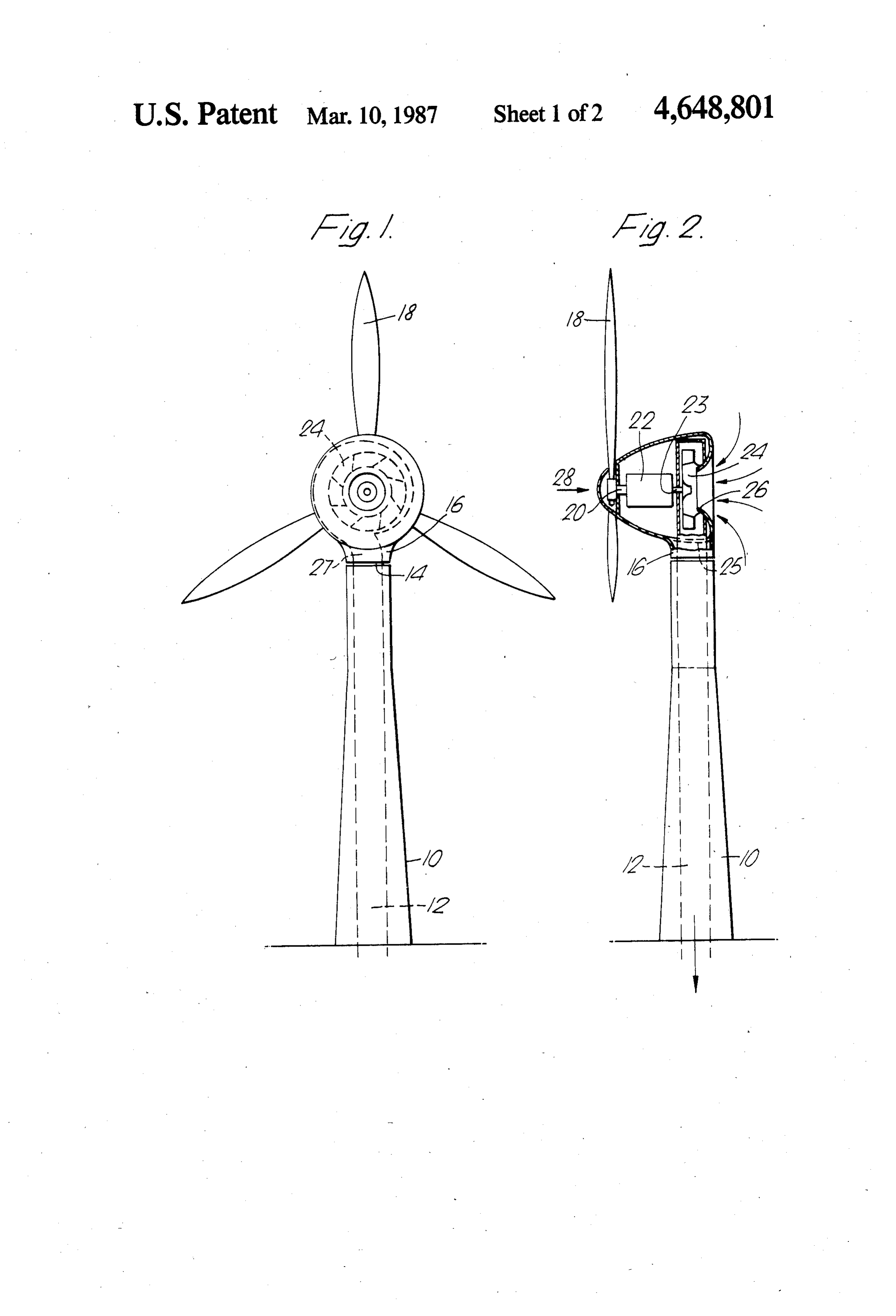
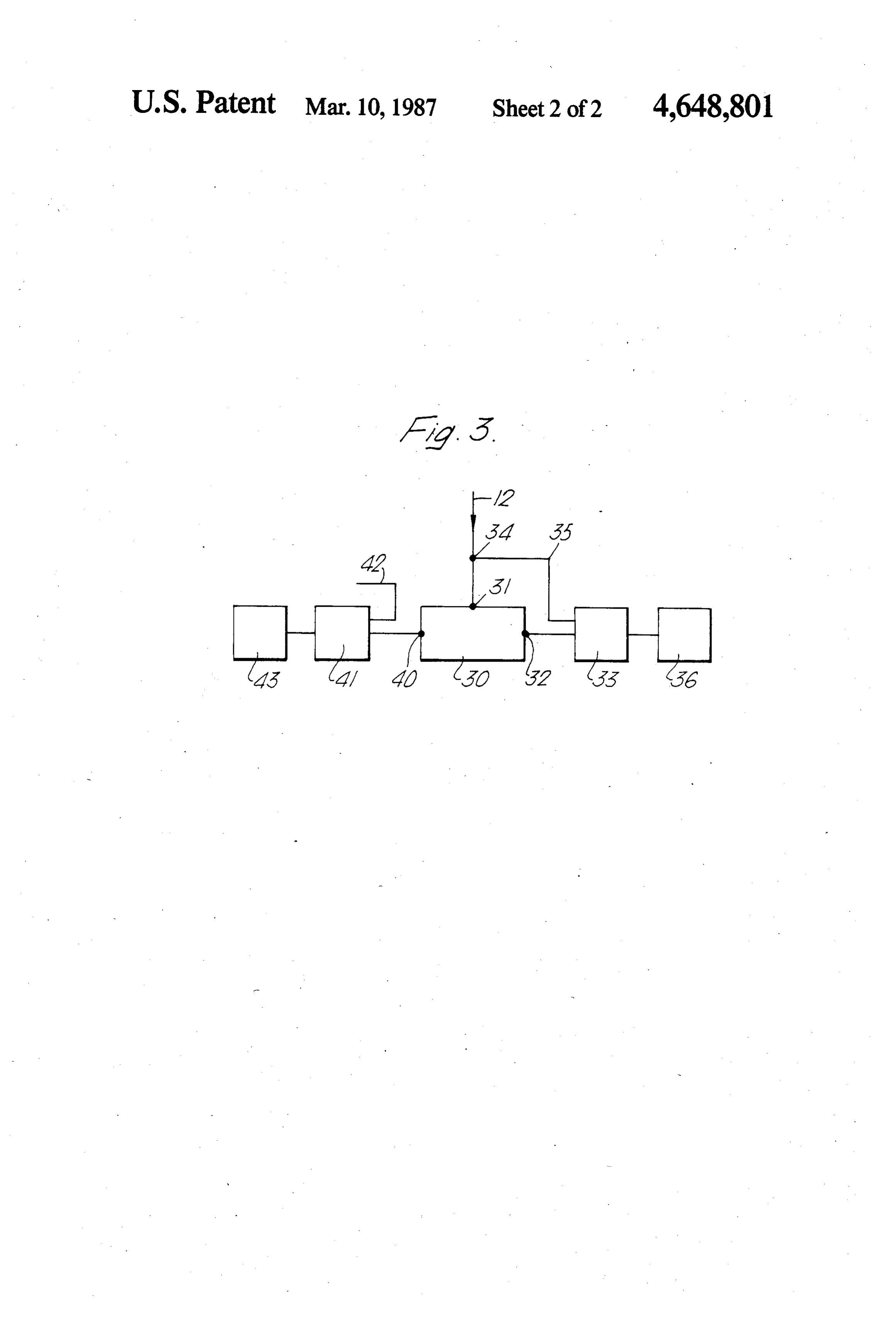
have shown that the maximum possible efficiency of a FIG. 1 is a rear elevation of one embodiment of wind wind turbine is of the order of 59%. That is to say the turbine assembly according to the invention; wind turbine is capable of extracting 59% of the energy FIG. 2 is a side elevation of the assembly of FIG. 1; available in the wind. 45 and
With the assembly of the present invention, because FIG. 3 is a block diagram illustrating how the air air is withdrawn from the blades of the turbine, there is under pressure for the air compressor may be used. a removal of this air build up so that the efficiency of the Referring to the drawing, there is illustrated a tower turbine can be significantly increased. 10 having a central duct 12 extending upwardly there The air can be removed immediately downstream of 50 within, and terminating in a rotary joint 14. Mounted on the blades of the turbine, or immediately upstream top of the tower is a rotatable head 16 in which is lo thereof. It is contemplated, also, that the air can be cated the joint 14, the head 16 carrying a conventional removed through apertures or perforations in the tur axial flow wind turbine rotor 18. Mounted on the shaft bine blades themselves. 20 of the rotor 18 is a speed increasing gearbox 22, the It is contemplated that all or only part of the power 55 output shaft 23 of which is connected to the fan or from the turbine can be used to drive the compressor. impeller 24 of a centrifugal compressor 25 included In a presently preferred construction, the inlet to the within the head 16.
compressor is located downstream of the turbine itself, The inlet 26 of the centrifugal compressor 25 is coax the inlet in fact pointing in the downstream direction. In ial with the fan and faces the downstream direction of this way the mounting for the turbine can also be the 60 wind which is shown moving in the direction of the mounting for the compressor, so that the compressor arrow 28 in FIG. 2.
can be caused to swivel with the turbine to take up the In operation, wind moving in the direction of the angle of incidence of the wind. Thus, the turbine is arrow 28 will cause the wind turbine to rotate and this preferably mounted on a tower assembly having a verti in turn will cause the fan 24 of the compressor 25 to cal duct therein, the vertical duct being connected to 65 rotate at a rather higher speed. The direction of rotation the outlet to the compressor. The duct can have a sim is the opposite to that of the impeller 18. ple pipe swivel joint at its top to allow the turbine and As a result of drawing air from behind the impeller 18 the compressor to rotate to take up the wind direction. into the compressor 25, the build up of air behind the
Page 5
impeller 18 is significantly reduced and this produces an whereby the compressor is driven thereby, an air inlet increase in the efficiency of the impeller 18. The result and an air outlet of said compressor, said air inlet being ing compressed air is fed down from the outlet 27 of the positioned downstream and sufficiently close to said compressor 25 via the rotary joint 14 and the duct 12 to blades and of a size effective to remove a substantial a reservoir 30, as shown in FIG. 3, where the air is fed quantity of air from the axial flow airstream in the vicin via valves 34 and 31. From the reservoir compressed air ity of said blades of said wind turbine thereby signifi can be fed to drive a pneumatic motor 33. Alternatively, cantly to improve the efficiency of said turbine, the the air can be fed direct to the motor through valve 34 outlet of the compressor being connected to said swivel and pipe 35. The motor 33 can be used to drive a gener joint, whereby air under pressure from said air compres ator 36. FIG. 3 shows another possibility in which the 10 sor can be fed down said duct to the lower end thereof air from the reservoir 30 flows through valve 40 to and a reservoir connected to said lower end of the duct, provide a source of compressed air for a gas turbine 41, effective to receive air under pressure from said com the gas of which can flow in via line 42. The gas turbine pressor, said head being allowed to swivel, so that the 41 could be used, for example, to drive an electric gen wind turbine can face the wind.
erator 43. 15 2. An assembly as claimed in claim 1, wherein said air FIG. 3 shows several different possibilities of using inlet is positioned on the downstream side of said wind the air under pressure from the air compressor 25, but turbine blades. - normally one would only be using one of these possibili 3. An assembly as claimed in claim 1, wherein said air ties. compressor is mounted coaxially with said wind tur I claim: 20 bine.
1. A wind turbine assembly comprising a tower, a 4. An assembly as claimed in claim 3, wherein said air head mounted on the upper end of said tower for swiv compressor is a centrifugal compressor and wherein the elling about a vertical axis, a duct extending upwardly means operatively connecting the wind turbine to the within said tower, and having an upper end and a lower blades cause said compressor to rotate in the opposite end, a swivel joint between said head and the upper end 25 rotational sense to said wind turbine. of said duct, a wind turbine mounted on said head and 5. An assembly as claimed in claim 4, wherein said having blades thereon, an air compressor mounted in means comprise a gear box having a drive ratio said head, with the axis of the wind turbine and com whereby said air compressor is driven at a greater rota pressor being substantially horizontal, means opera tional speed than saidsk wind is it
tively connecting the air compressor to the turbine, 30
Provenance
- Collection
- Cited prior art
- Original PDF
- patentimages.storage.googleapis.com →
- Filed
- 1986-05-21
- Pages
- 5
- Method
- pdftotext (the PDF's own text layer) + pdftoppm 300dpi page scans
- Source
- Google Patents bibliographic record
- Granted
- 1987-03-10
- Inventors
- Robert R. Wilson; James Howden and Co Ltd
- Transcribed from
- patentimages.storage.googleapis.com →