patent · US4792302
Continuous solder reflow system
20 December 1988
Page 1 — bibliographic record
United States Patent (19) 11 Patent Number: 4,792,302 Baker et al. 45) Date of Patent: Dec. 20, 1988 (54 CONTINUOUS SOLDER REFLOWSYSTEM 4,474,552 10/1984 Smith ...................................... 432/8 4,529,379 7/1985 DiCastri................................ 432/59 75) Inventors: Michael C. Baker, Wilmington; W.
James Hall, Newton Corner, both of Primary Examiner-Henry C. Yuen
Mass. Attorney, Agent, or Firm-Spencer T. Smith 73) Assignee: Dynapert-HTC Corporation, 57) ABSTRACT Farmington, Conn. o g Ol An oven includes a plurality of pairs of upper and lower 21 Appi. No.: 116,186 spaced non-focused infrared heater panels. Product is (22 Filed: Nov. 3, 1987 conveyed between these panels to effect solder reflow. To increase heat transfer and to achieve temperature (51) Int. Cl." ................................................ F27B 9/28 uniformity, air is forced through equally spaced holes (52) U.S. C. ...................................... 432/59; E. drilled in the insulating block of one or more upper d heating panels. To define an equal flow through these 58) Field of Search ...................... 432/8, 59, 175, 202 holes, a valve is placed below the air intake opening to (56) References Cited define an annular opening between the panel casing and
3,744,963 7/1973 Flynn was a saw how wove or essa as as a 432/59 is matched to the annular area between the casing and the valve.
4,116,620 9/1978 Stibbe.................................... 432/59 4,217,090 8/1980 Whike et al. .......................... 432/59 4,378,207 3/1983 Smith .................................... 432/59 2 Claims, 2 Drawing Sheets
Page 2
Drawing sheet — no readable text.
Page 3
O D (ded ded(DOCD6D0CD006 (6)
O (D. de Oede Doe deco (D) ( ) D (D (do Do () (Deebee (Dee e9 Doooooooooooooooo
e() do e o 00 dodoo Good
Page 4
panels downwardly against the product to achieve con
CONTINUOUS SOLDER REFLOW SYSTEM vective heat transfer. This air is then pulled through the insulating block holes 25 and then through the large
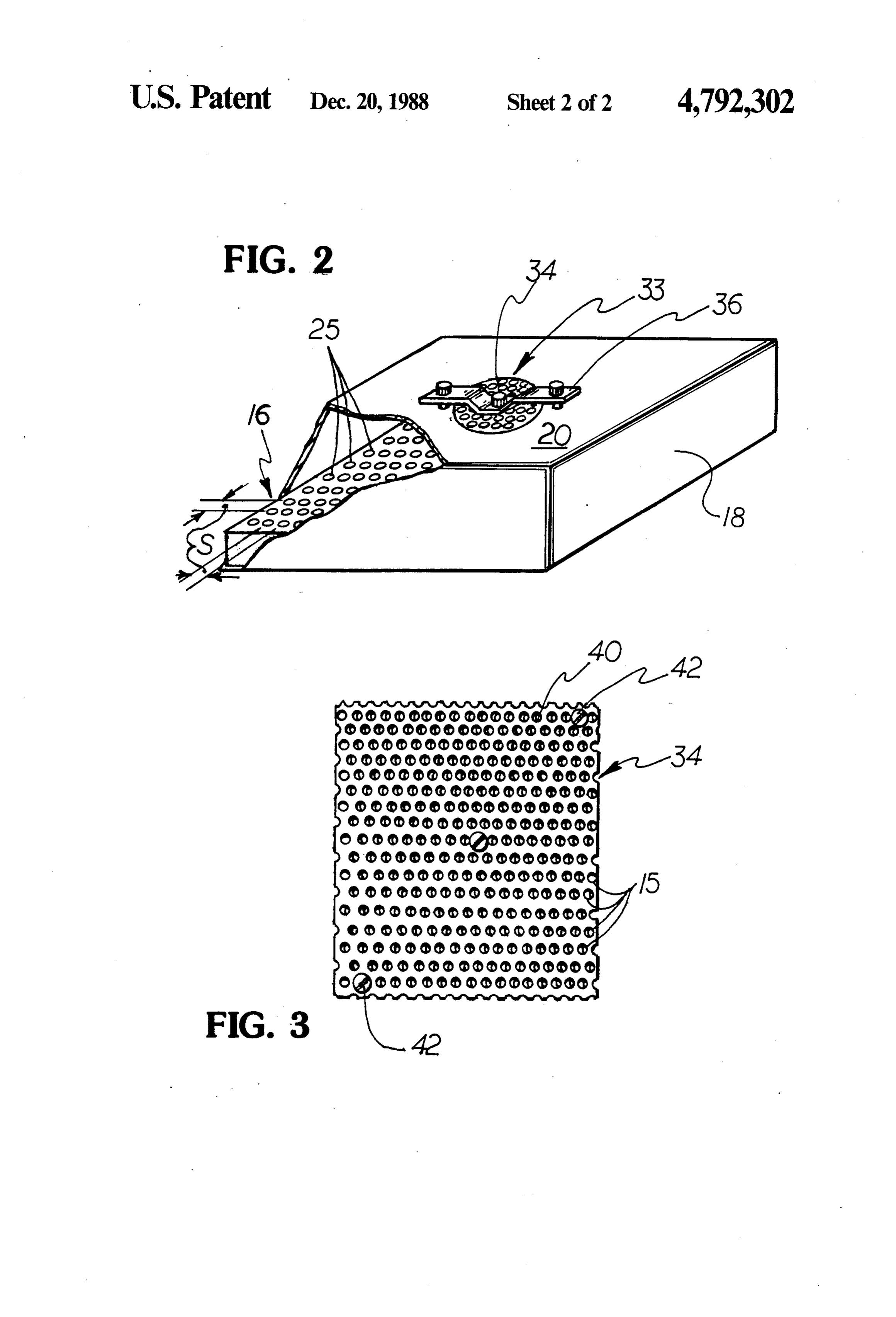
Reflow soldering of electronic components on casing opening 26 of the lower panels and exhausted printed circuit boards can be achieved by conveying the 5 from an exhaust manifold 30 by a fan 32. product through an oven which heats the solder to its To establish substantially the same volume of air flow liquidus temperature. The heating elements may be downwardly through each hole in an upper panel, a two non-focused, infrared panels which are arranged in passageway valve 33 is defined at the housing opening upper and lower rows spaced to permit passage of the 25. A perforated valve body 34 which is a planar mem product therebetween. Since infrared heating is line of 10 ber at least as big as the opening and which is secured in sight heating, any shadowed surface or component will parallel relation with the top surface by a mounting heat up at a different rate than the same surface or com bracket 36 is located a selected vertical distance D ponent which is directly exposed to the infrared source. below the top surface of the panel housing thereby To increase temperature uniformity and to increase the defining an annular opening or passageway of selected heat transfer rate, holes may be drilled through an area between the periphery of the valve body and the upper panel so that air can be forced through the panel 15 top surface 20 of the casing. A second passageway 15 is to impact against the product thereby causing substan collectively defined by the holes or perforations in the tial convective heat transfer. The air is then pulled valve body. The ratio of these passageway areas con through similar holes in the corresponding lower panel trols the pressure throughout the air volume and can be and exhausted from the system. adjusted by varying the size of these two passageways When such holes were located at equal spacings 20 to define a uniform pressure throughout the casing throughout the panel, uneven heating took place across above the insulating block so that the volume of air the conveyor. To overcome this deficiency, more holes flowing through each insulating block hole will be sub have been defined in the panel along the sides of the stantially the same thereby assuring uniform heating conveyor than along its center and great efforts are 25 across the conveyor.
taken to define a hole pattern that will yield the desired In the preferred embodiment, the valve is defined by uniformity.
It is an object of the present invention to utilize infra shiftedand upper lower perforated sheets which are laterally red panels having uniformly spaced holes and yet sheets are securedoblong to define openings. The laterally shifted to each other by suitable fasteners 42.
achieve uniform across the conveyor. A pressure change through the perforated valve body is Other objects and advantages of the present invention 30 controlled by the ratio of open to closed pathways will become apparent from the following portion of the within the boundary dimension of the valve. specification and from the drawings which illustrate in What is claimed is:
accordance with the mandate of the patent statutes a 1. A continuous solder reflow system comprising presently preferred embodiment of the invention. an oven including a plurality of pairs of upper and
lower non-focused infrared heater panels spaced to
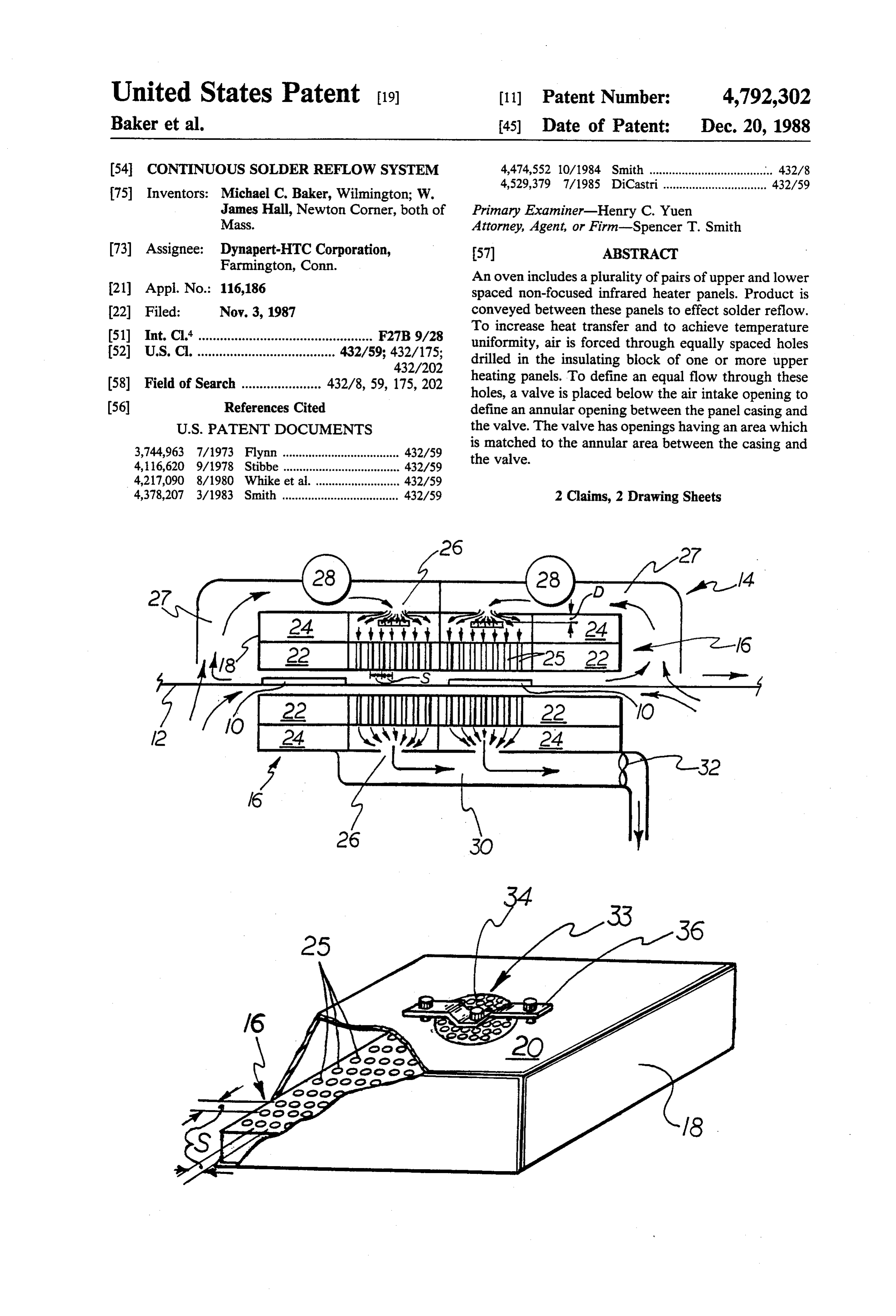
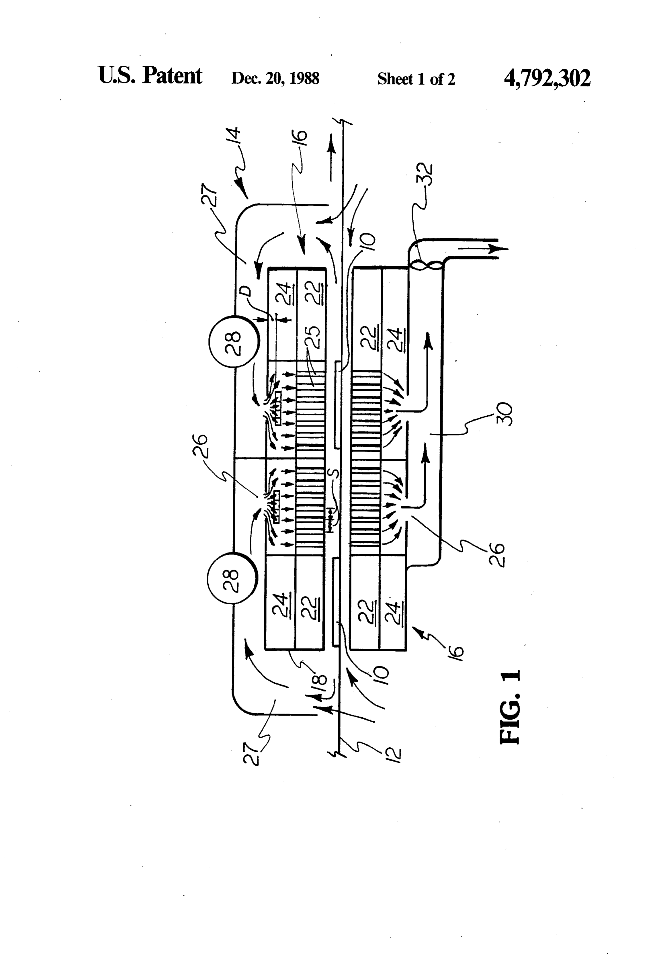
FIG. 1 is a schematic illustration of a continuous solder reflow system made in accordance with the define a heating zone, teachings of the present invention; conveyor means for conveying product to be reflow FIG. 2 is an oblique view of one of the center non soldered through said heating Zone, focused infrared heating panels of the system illustrated each of said heater panels including in FIG. 1 with a corner cut away to show the insulating a casing open at the bottom, and block; and an insulating block supported within said bottom FIG. 3 is a top view of the valve element used in the opening and spaced from the top surface thereof, heating panel illustrated in FIG. 2. at least one of the upper panels additionally including Produce 10 (for example, a printed circuit board with 45 a plurality of equally spaced and sized holes ex surface mounted components placed on the board for tending from the top surface to the bottom sur reflow soldering) is conveyed by a conveyor 12 face of said insulating block, and through an oven 14 having four adjacent upper and an air intake opening in the top surface of said lower pairs of vertically spaced non-focused infrared casing, heating panels 16. These panels all start out as standard 50 means for forcing air through said air intake opening panels having a metallic box-like casing 18 having a top into said casing, surface 20 and an open bottom. An insulating block 22 valve means including a flat body portion at least as is located within the bottom opening and defines a large as said air intake opening with a plurality of closed volume of air 24 with the top portion of the of holes extending therethrough, and casing 18 (While the upper panel is placed with the 55 means for mounting said body portion below said air insulating block at the bottom and the lower panel is intake to define an annular opening between said placed vice versa, the top of the panel is intended to top surface and said valve body portion, the ratio refer to the end opposite the insulating block.). of the area of said annular opening and the area of To increase heat transfer to the product as it passes said valve body holes being adjusted to define a between the second and third pairs of upper and lower uniform pressure throughout said casing above said panels 16, holes 25 are drilled through the insulating insulating block so that a uniform volume of air blocks from the top surface to the bottom surface of the will flow through each of said holes in the insulat block. The holes all are of the same size and are equally ing block.
spaced S in an X-Y grid. A large opening 26 is centrally 2. A continuous solder reflow system according to defined in the top casing surface 20 of the second and claim 1, wherein said valve means comprises first and third upper and lower pairs of panels. Air can be drawn 65 second sheets of identically perforated material and into an intake manifold 27 by a draft inducer 28, and further comprising means for securing said sheets in forced into the casing 18 and through the insulating offset relation.
block holes 25 of the second and third (center) upper ck k st k
Provenance
- Collection
- Cited prior art
- Original PDF
- patentimages.storage.googleapis.com →
- Filed
- 1987-11-03
- Pages
- 4
- Method
- pdftotext (the PDF's own text layer) + pdftoppm 300dpi page scans
- Source
- Google Patents bibliographic record
- Granted
- 1988-12-20
- Inventors
- Michael C. Baker; W. James Hall; Dynapert HTC Corp
- Transcribed from
- patentimages.storage.googleapis.com →