patent · US5477703
Geothermal cell and recovery system
26 December 1995
Page 1 — bibliographic record
United States Patent (19) 11 Patent Number: 5,477,703 Hanchar et al. 45) Date of Patent: Dec. 26, 1995 (54) GEOTHERMAL CELL AND RECOVERY 4,139,321 2/1979 Werner ....... . 405(154 SYSTEM 4,142,576 3/1979 Perry et al. ............................... 165/45 4,286,574 9/1981 Vrolyket al............................ 126/400 76 Inventors: Peter Hanchar, 88 Montgomery Rd., 4,325,228 4/1982 Wolf.......................................... 62/260 Scottdale, Pa. 15683; Harry J. 4,375,831 3/1983 Downing 62/260 X 4,378,908 4/1983 Wood ...................................... 237/2 B
Hanchar, 812 Forest Ave., Belleforte, 4,392,531 7/1983 Ippolito . 166/278 Pa. 16823 4,452,227 6/1984 Lowrey, III ............................. 26,415 4,570,452 2/1986 Bingham .... ... 62,260 21 Appl. No.: 222,234 4,674,561 6/1987 Kelley ... ... 165/45 4,741,389 5/1988 Smith ..... ... 165145 22) Filed: Apr. 4, 1994 4,753,285 6/1988 Rawlings .................................. 165.45 51 Int. Cl. ........................... E28D 7/12 Primary Examiner-Henry A. Bennet (52) U.S. Cl. ................................................. 62/260; 165/45 Assistant Examiner-William C. Doerrler 58 Field of Search .................................... 62/260, 238.6, Attorney, Agent, or Firm-Gipple & Hale; John S. Hale
(56 References Cited An apparatus comprising a geothermal cell and recovery
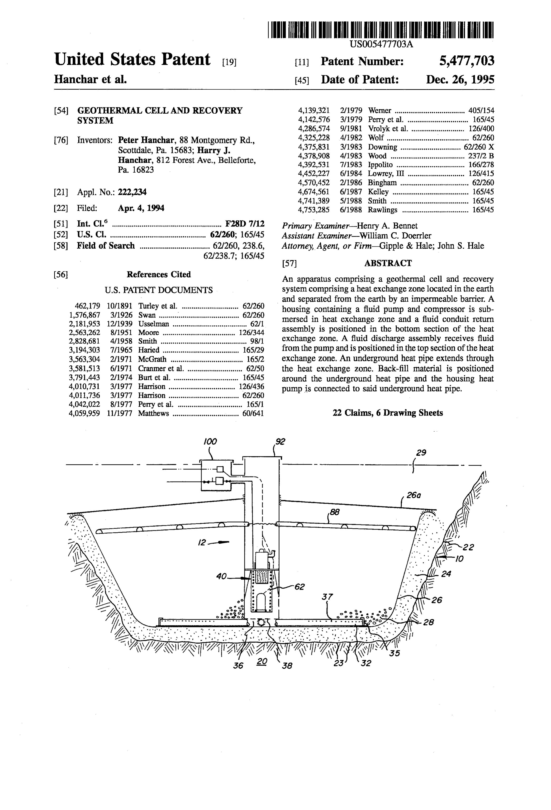
and separated from the earth by an impermeable barrier. A 462,179 10/1891 Turley et al. ....................... 62.260 housing containing a fluid pump and compressor is sub 1,576,867 3/1926 Swan ........................................ 62/260 mersed in heat exchange zone and a fluid conduit return 2,181,953 12/1939 Usselman ...................................... 62/1 2,563,262 8/1951 Moore ......... ... 126/344 assembly is positioned in the bottom section of the heat 2,828,681 4/1958 Smith ............................................ 98/1 exchange Zone. A fluid discharge assembly receives fluid 3,194,303 7/1965 Haried ....................................... 65/.29 from the pump and is positioned in the top section of the heat 3,563,304 2/1971 McGrath ......... ... 16572 exchange Zone. An underground heat pipe extends through 3,581,513 6/1971 Cranmer et al. ... 62150 the heat exchange zone. Back-fill material is positioned 3,791,443 2/1974 Burt et al. ................................. 65/45 around the underground heat pipe and the housing heat 4,010,731 3/1977 Harrison ...... ... 126,436 pump is connected to said underground heat pipe. 4,011,736 3/1977 Harrison .................................... 62/260 4,042,022 8/1977 Perry et al. ................................. 1657 4,059,959 11/1977 Matthews .................................. 60/64 22 Claims, 6 Drawing Sheets
siz7%), Fix
Page 2
Drawing sheet — no readable text.
Page 3
Drawing sheet — no readable text.
Page 4
Drawing sheet — no readable text.
Page 5
Drawing sheet — no readable text.
Page 6
Drawing sheet — no readable text.
Page 7
Drawing sheet — no readable text.
Page 8
GEOTHERMAL CELL AND RECOVERY dispersion. The pump re-circulates the water through the SYSTEM coils and the heat exchanger to effect aheat transfer to a heat BACKGROUND OF THE INVENTION pump having a refrigerant line which runs through the heat exchanger.
The present invention is directed towards a geothermal 5 Still another U.S. Pat. No. 4452,227 of Jun. 5, 1984, cell and recovery system. discloses a pit with a plastic liner filled with gravel and rock. The most common source of heating or cooling is the Brine is pumped from the pit into a spray tray exposed to surrounding air because of its accessibility. However, since outdoor air and returned into the pit. The brine is pumped out the air is heated to high temperatures in the summer and cold of the pit into a heat exchanger. temperatures in the winter, it is the least efficient source of 10 Another U.S. Pat. No. 4,010,731 of Mar. 8, 1977, dis cooling and heating. The use of water as a heat source is more efficient than atmospheric air. However, the impurity, closes aheat storage pit with a water impermeable liner tank quality, quantity and disposal of water and the corrosion made of plastic such as vinyl or polyethylene. A layer of problems of pipes handling the water have minimized the sand a few inches thick is spread on the bottom of the tank use of such systems. 15 to prevent puncturing. Protection for the sides of the tank
It has been established since at least the early 1900's that may be in the form of a layer of sand or alternatively, plastic earth (be it soil, clay or stone) was a good insulator. This or plastic foam. The tank is filled with gravel and stones of made it possible to store ice for long periods of time in pits uniform size to provide void spaces. Earth taken from the pit as it is known that the temperature of the earth remains is used for filling the tank after it has been screened to rather constant at as shallow a depth as 36 inches or in colder 20 develop water circulation voids. Water is then pumped regions under the frost line. through the aggregate and an insulating barrier which There have been numerous attempts to recover or utilize extends down from the top of the tank traps the hottest water heat from the earth. Some of the earlier recovery attempts in the central portion while the coolest waterflows under the used large numbers of refrigerant lines buried beneath the barrier into the side portion. In the central portion, the surface of the earth. Others developments required the 25 warmest water rises to the top where its heat comes into drilling of numerous, and sometimes deep, water wells to contact with the heat exchangerfor the purpose of providing develop a sufficient water supply. Still other developments hot water and heat to the house. used a brine solution with piping buried beneath the soil. Conventional heat pump systems utilize a compressor, These earlier attempts have major drawbacks which have fan, condensing and evaporating coils, control valves, refrig prevented their success and curtailed development. Modern erant gases and air in order to provide a source of cooling in day home owners do not have sufficient land needed to bury 30 summer and a source of heating in fall, winter and spring. a piping array underground and are precluded from such The condensing coil, fan compressor and controls are known installation by Zoning ordinances. Other home owners lack as the 'outdoor unit. During operation, the outdoor unit the certainty of hitting water of sufficient quantity to afford either extracts heat from or releases heat to the ambient air drilling a well or wells. Furthermore using a brine solution 35 depending upon the cycle used. This transfer of heat to or which is circulated in large piping arrays underground is from the outdoor unit is accomplished by forcing air through undesirable because of the environmental problems which the condenser coils by means of a fan. include potential possibility of contamination of the sub-soil While the conventional heat pump uses air as its primary and ground water and the large building lot size required. transfer medium, the geothermal cell and its recovery system The prior art devices used were not as intrinsically safe, 40 invention use a different approach. First, a thermal mass is environmentally friendly, low in maintenance or low in achieved by the construction of the geothermal cell and energy consumption as the present recovery system. filling it with clean water. Second, the recovery system A number of devices have been used in the prior art to utilizes a submersible pump, a submersible refrigerant com recover or utilize heat from the earth. One such device is pressor and a submersible coil to transfer heat to or from the disclosed by U. S. Pat. No. 4,042,012 of Aug. 16, 1977 45 geothermal cell. The water used in the geothermal cell is the which shows the use of a heat pump in combination with a primary transfer medium. Water within the geothermal cell heat exchanger and heat sink. The heat sink uses back-fill has a specific heat of 1.0 btu?ib/F and has a constant soil enhanced with water sub-particles to transfer heat (cold) temperature (approximately 54 F) as opposed to air which to buried heat pipes having coiled portions. The heat pipes has a low specific heat (approximately 0.24 btu/b/F at sea are formed with a closed fluid circuit which runs through a 50 level) and wide temperature variations (-10 F. to 11 F). heat exchanger which also contains a second closed conduit This range falls within heat pump and heat exchanger which communicates to with a heat pump. maximum efficiency ranges.
In construction of the heat sink, a hole is dug in the Water, having superior heat transfer characteristics as ground, and a bottom water impermeable sheet of synthetic compared to air (800 times greater specific volume and four polymer material is laid to conform to the hole walls. A 55 times greater specific heat) makes the geothermal cell and coiled heat pipe is laid in the interior of the hole and the soil recovery system far more efficient then the conventional previously removed is mixed with water absorbent particles heat pump system.
with the mixture then being used to bury the pipe. A roof is placed on the upper surface of the back-fill soil soaked water SUMMARY OF THE INVENTION absorbent particles. The remainder of the back-fill is placed 60 over the roof. In the present invention, the geothermal cell and recovery Another U. S. Pat. No. 4,142,576 of Mar. 6, 1977, system is utilized for enhanced heat transfer. The geothermal discloses a heat pump which is similarly connected with a cell comprises a heat exchange zone located in the earth and heat exchanger. A pump located outside the heat sink pumps separated from the earth by an impermeable barrier filled fluid through submerged coils which are placed in a pit 65 with gravel providing voids for water circulation. The recov having a fluid impermeable plastic wall. The pit is filed with ery system comprises a housing containing a fluid pump and back-fill soil and water soaked absorbent particles in random compressor located in said heat exchange Zone surrounded
Page 9
by the gravel with a fluid conduit return assembly connected of PVC, PVA approximately 50 to 60 mil thickness and to the housing positioned in the bottom section of the heat having a low insulating 'R' value is placed over the con exchange zone. A fluid transportation means receiving fluid toured sand/clay 24.
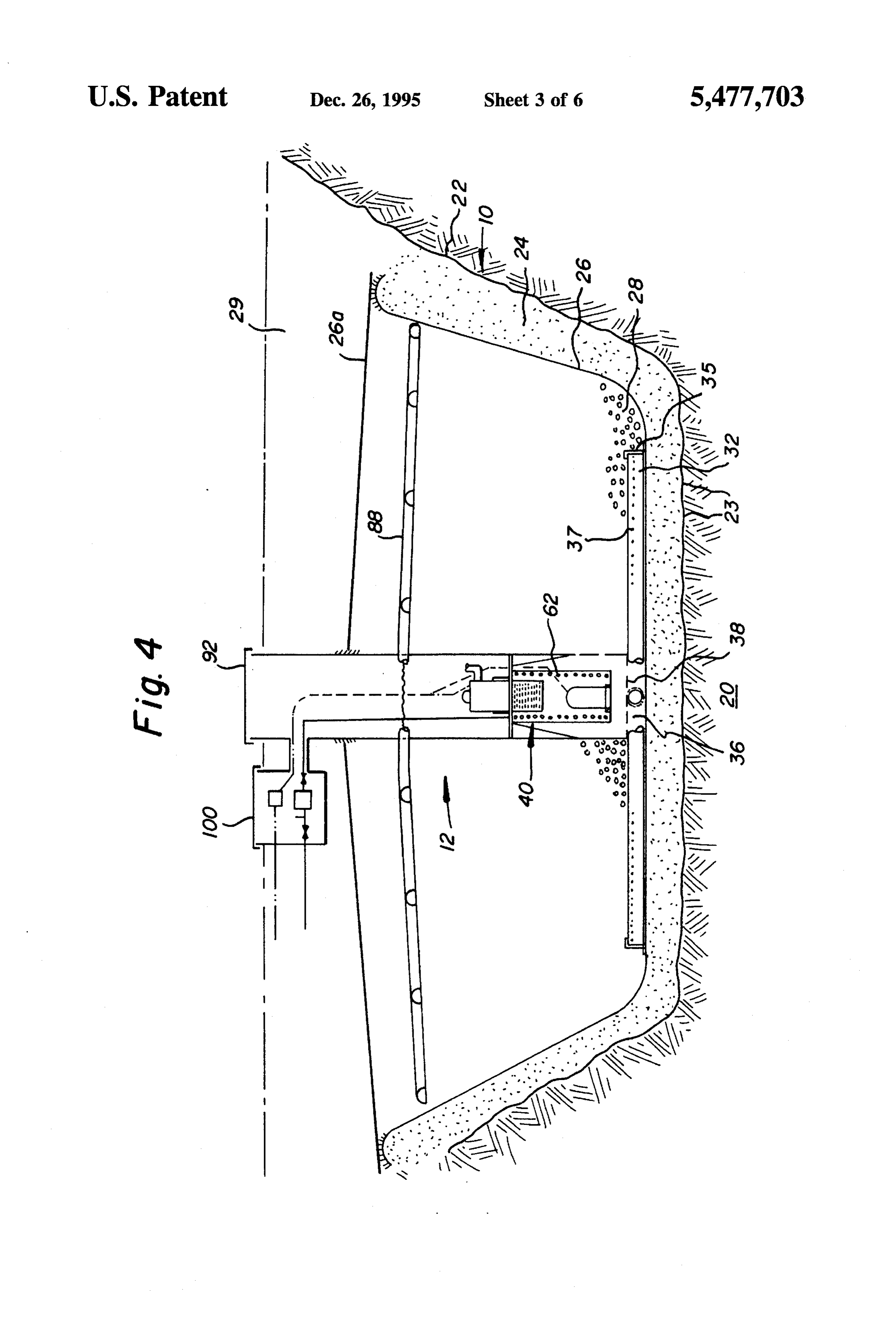
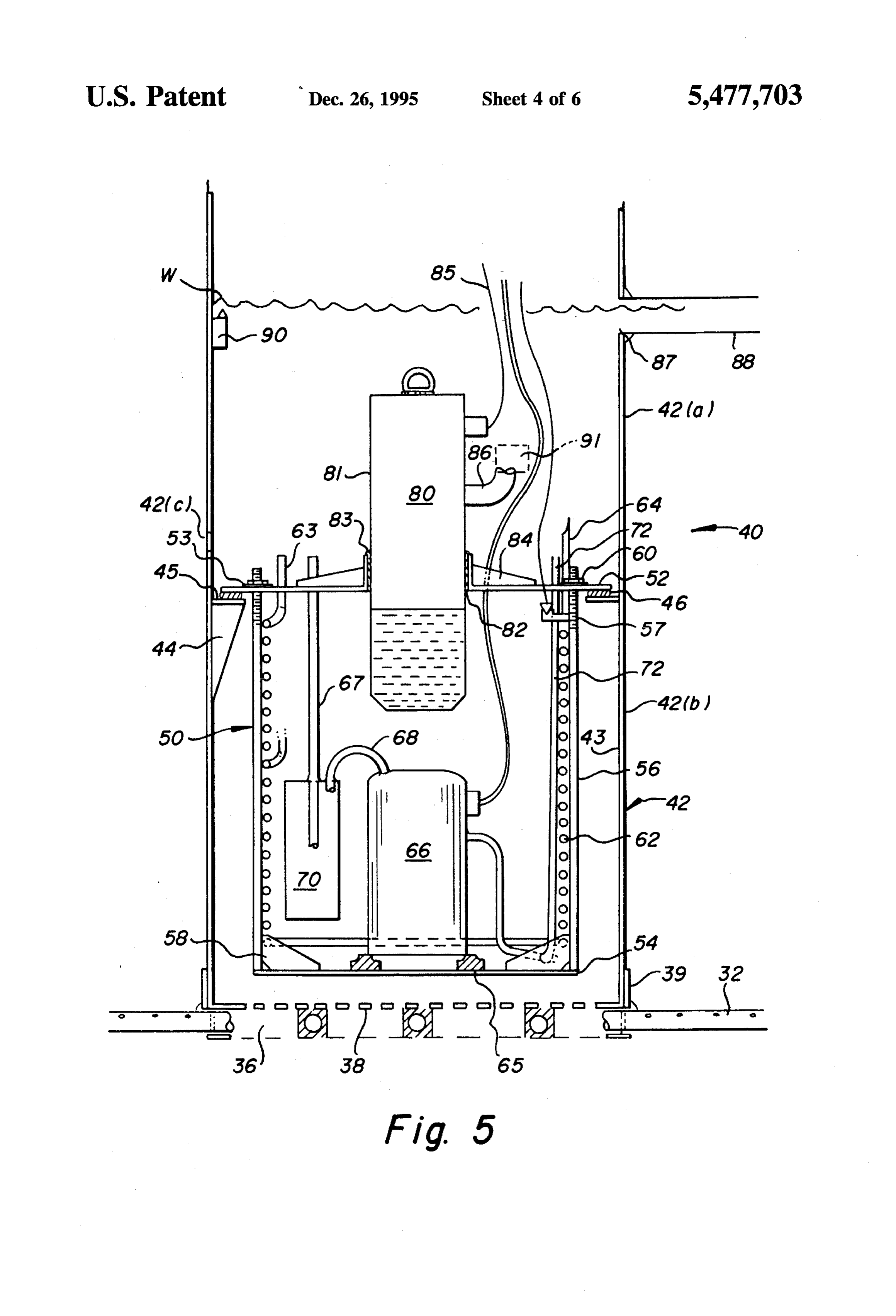
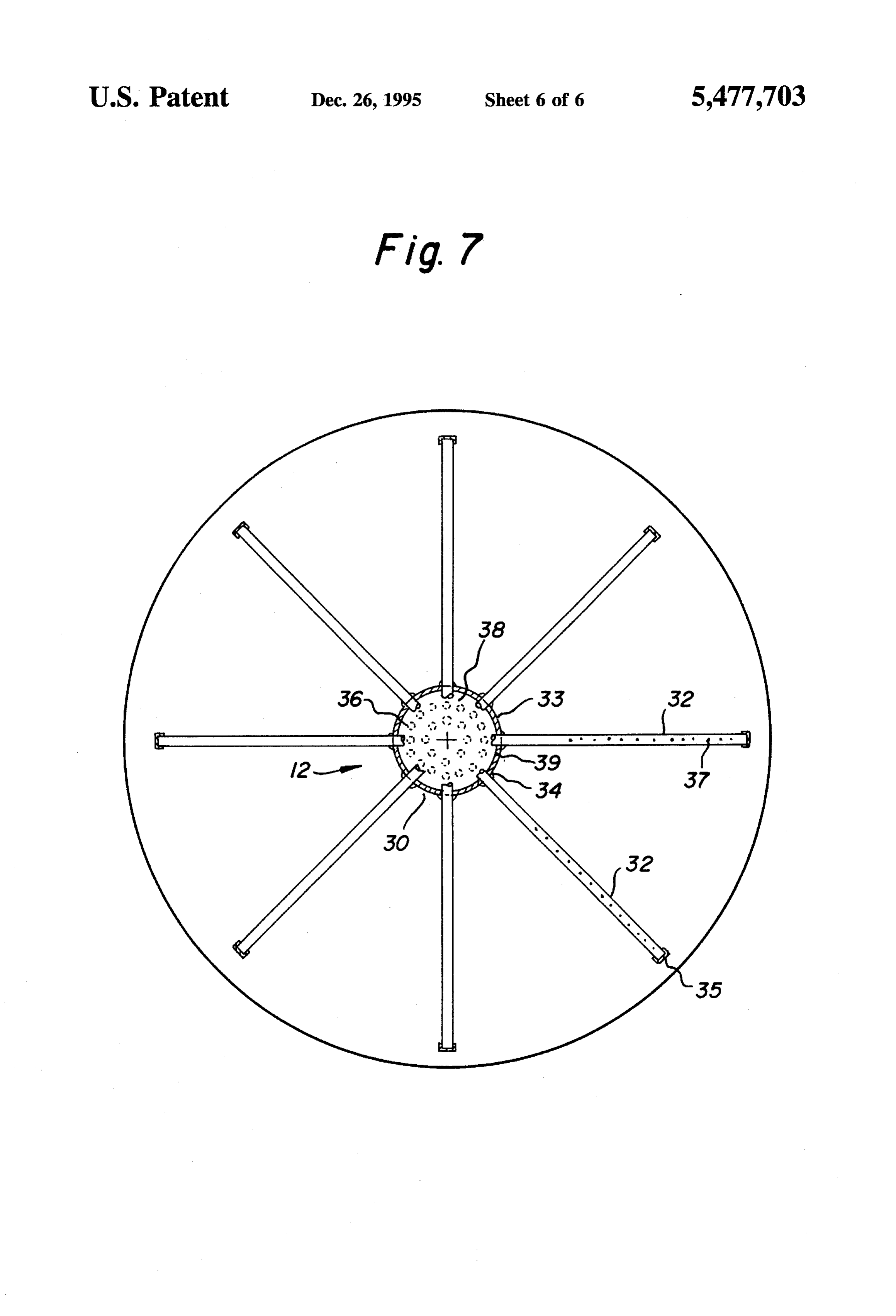
from said fluid pump positioned in the top section of the The recovery assembly 12 is placed on the barrier 26 as housing and discharges to fluid along the top of the heat shown in FIGS. 1 and 4. A cylindrical support base member exchange Zone. 30 which is most clearly shown in FIG. 7 is placed on the It is an object of the invention to provide a thermal mass top of the barrier 26 and a plurality of perforated recovery to provide a novel water-earth heat transfer system. pipes 32 are mounted in apertures 34 formed in the side wall Another object of the invention is to provide a novel heat 10 33 of the support base member 30. The open ends of the pipes lead into a chamber 36 in the base member formed by exchange construction for extracting heat from the earth into the side wall 33 and a perforated top plate 38. The recovery a water filled, insulated heat sink to be cooled which pipes 32 are sealed in apertures 34 with an expansion foam operates with a minimum of moving parts and is economical seal material. Each of the recovery pipes 32 is preferably and efficient to use. closed at the distal end with an end closure member 35 and Another object of the invention is to use the earth itself by 5 is open at the proximal end which is positioned in chamber laying a heat exchanger assembly in an underground hole 36 so that water collected through the perforations 37 in the which has been covered with an impermeable layer of pipe body is carried into the chamber 36 and where it plastic and back-filling the hole with crushed rock or gravel circulates upward through the perforated top plate 38 into so that the heat exchanger assembly is covered with the the stack assembly 40 as will be more fully described. A crushed rock or gravel. The filled hole is then filled with 20 circular flange support collar 39 is secured by welding, liquid to increase heat transfer between the liquid and buried adhesives or heat sealing depending upon the material used heat exchanger assembly. on top of the perforated top plate 38 to hold a stack tube In the accompanying drawings, there is shown an illus assembly 40 in a supported upright position. trative embodiment of the invention from which these and The stack tube assembly 40 is placed on the top surface other of objectives, novel features and advantages will be 25 of the perforated top plate 38 and the base of its cylindrical readily apparent. housing is surrounded by the flange support collar 39 to keep it in a fixed position on the support base member 30. The
BRIEF DESCRIPTION OF THE DRAWINGS stack tube assembly cylindrical housing 42 is constructed in two sections 42(a) and 42(b) which are connected together
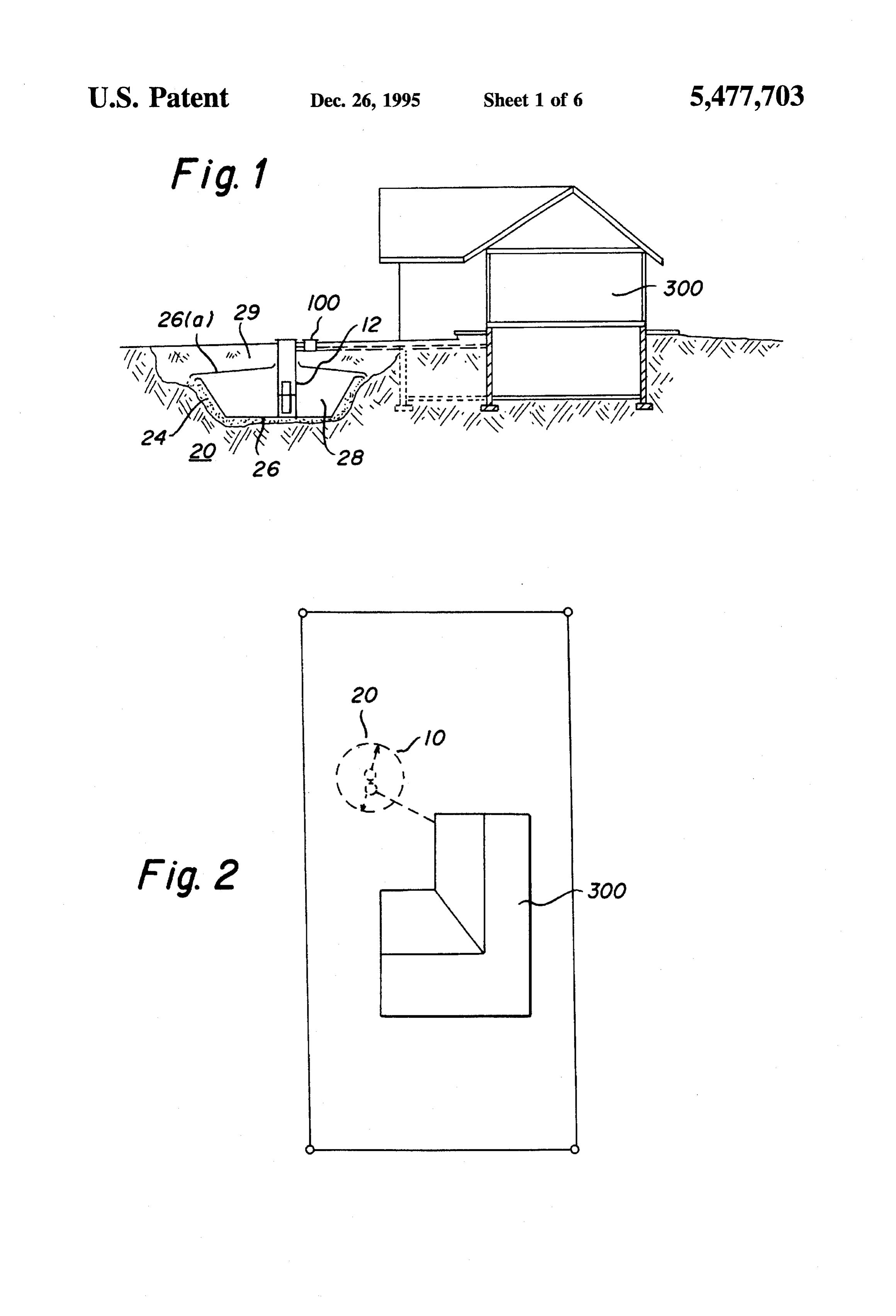
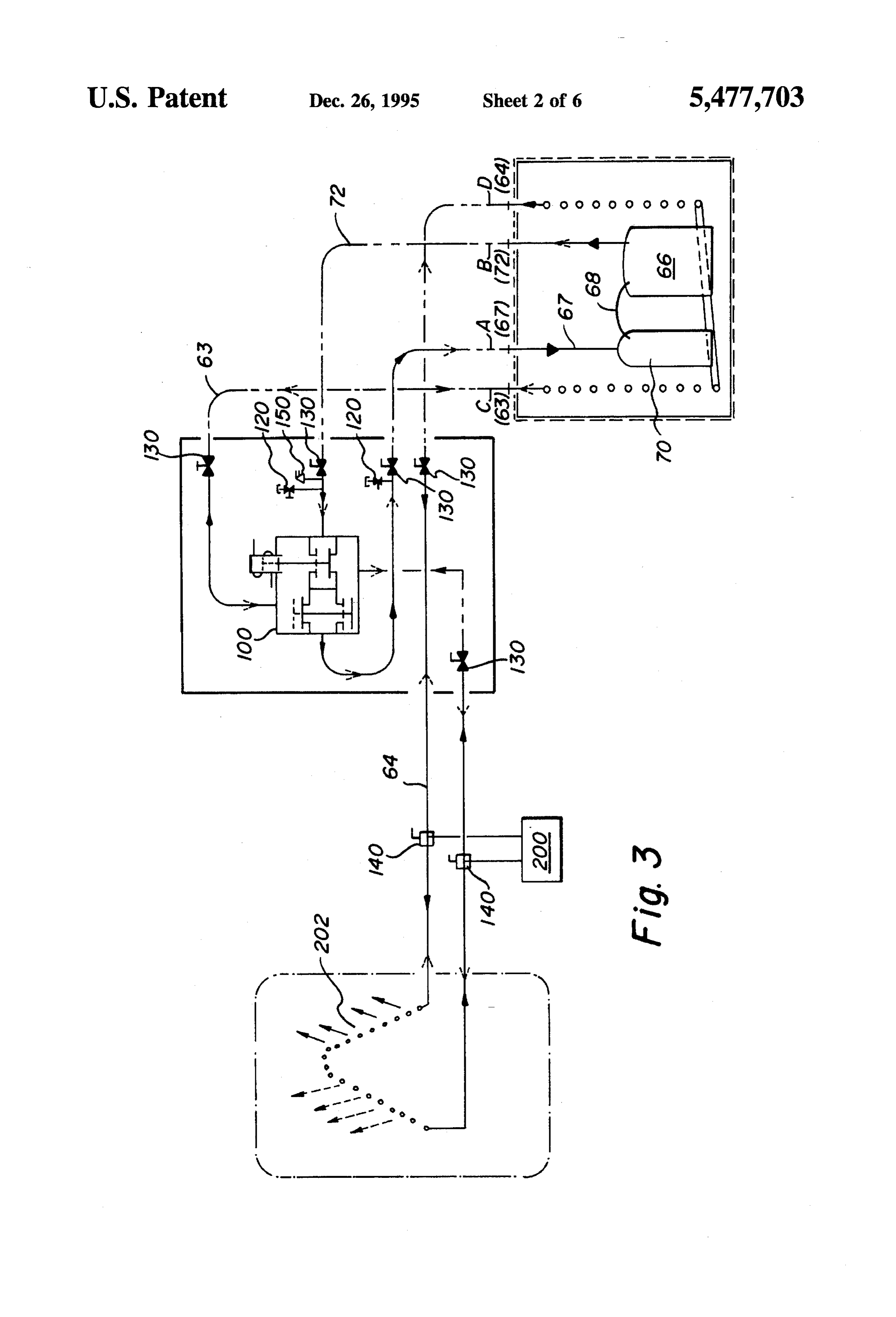
FIG. 1 is a schematic cross sectional view of the geother 30 by a slipjoint and seal 42(c) as shown in FIG.5. The housing mal cell and recovery system of the present invention used is preferably constructed of stainless steel or corrosion to air condition a house; resistant material to prevent corrosion. Housing section FIG. 2 is a reduced top plan schematic view of the 42(b) has an interior support shelf 44 which is secured to the geothermal cell and recovery system invention and house inner surface 43 of the cylindrical housing. The support shelf shown in FIG. 1; 35 44 may take the form of a plurality of flanges or brackets or FIG. 3 is a schematic diagram of the fluid flow and fluid a continuous flange. The top surface 45 of the support shelf controls of the present invention; is provided with a gasket 46 or a bead of hydraulic silicone sealant upon which is mounted the removable recovery
FIG. 4 is an enlarged cross sectional elevational view of assembly the geothermal cell and recovery system and heat sink; 50.
FIG. 5 is an enlarged cross sectional view of the recovery 40 The recovery assembly 50 is constructed with a top plate system shown in FIG. 4; 52 which sits on gasket 46 or the top surface 45 of the support shelf and a bottom plate 54 which is mounted and
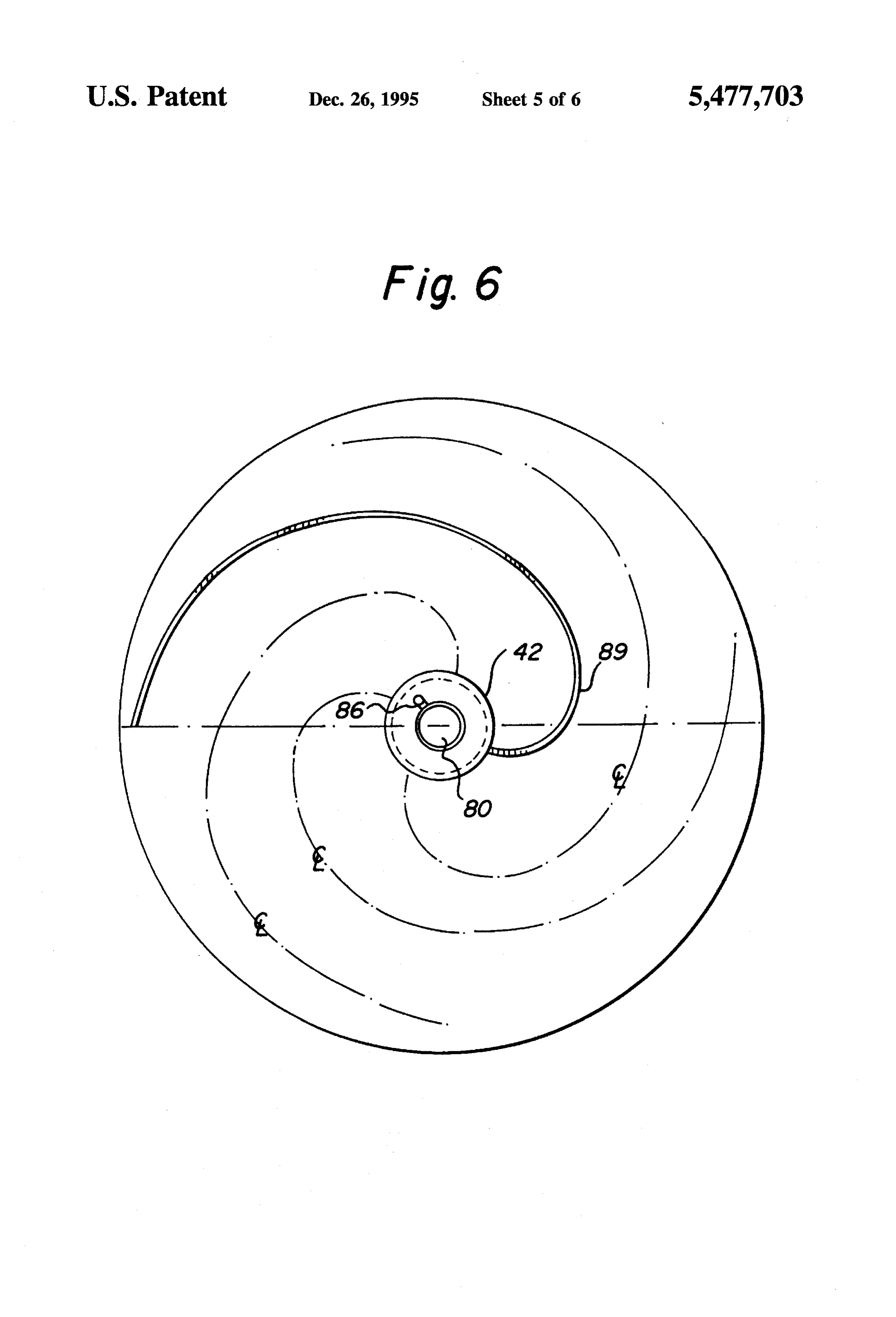
FIG. 6 is a top plan view of the fluid distribution system supported from the top plate by a plurality of support rods of the recovery system; and 56. Each support rod 56 has one end welded or secured to FIG. 7 is a top plan view with housing removed of the 45 the bottom plate 54. The upper section of each support rod recovery assembly of the recovery system. 56 is threaded at 57 to receive a nut and washer 60 which keeps the assembly secured together and the top and bottom
DETAILED DESCRIPTION OF THE plates in a predetermined spaced arrangement. The top plate INVENTION 52 is provided with a plurality of throughgoing apertures 50 through which the threaded end of the rod 56 extends
The preferred embodiment and best mode of the invention allowing easy threading of the nut. A support bracket 58 is is shown in FIGS. 1-7 and is shown by the figures. also secured to the support rod 56 and bottom plate 54 to The geothermal cell and recovery system is comprised of proved additional strength and stability to the structure. two primary components used in connection with a heat A one piece heat exchanger coil 62 made of copper or exchanger 202 and/or heat pump 200 of a building such as 55 stainless steel with lead and exit conduits 63 and 64, also a house 300. One is the geothermal cell assembly 10, and the designated in FIG.3, as Cand D is dropped into the recovery other is the recovery unit 12. assembly prior to mounting of the top plate and is seated on Construction of the geothermal cell assembly 10 begins the top planar surface of the support brackets 58 which are with the excavation of the earth 20 to form a pit approxi secured to the bottom plate. A submersible compressor 66 is mately 10 to 15 feet in diameter (12"x20' rectangle) and 60 seated in the bottom of the recovery assembly on vibration approximately 8 feet deep. The sides 22 and bottom 23 of the seats 65 secured on the top surface of the bottom plate 54 pit are smoothed, contoured andlined with stone-free clay or and has an accumulator tank 70 mounted thereto. As shown sand 24 as shown in FIGS. 1 and 4. The clay or sand 24 liner in FIGS. 3 and 5 the compressor 66 receives fluid namely is compacted and smoothed to a uniform surface or contour. refrigerant gas via conduit 67 and a suction conduit 68 which If desired the sides and bottom of the pit can be formed with 65 lead respectively into and out of accumulator tank 70. a two layer medium comprising a bentonite clay blanket Refrigerant gas leaves accumulator tank 70 via suction which is placed over a base sand fill. A polyvinyl barrier 26 conduit 68 into the compressor 66 and is discharged via
Page 10
conduit 72 or B as designated in FIG. 3 into a standard off Sand or fine clean soil or fill 29 is carefully placed until the shelf reversing valve 100. A submersible pump 80 is it reaches the top of the cover 92. The excavation is filled mounted in aperture 82 cut in the top plate 52 and is until normal grade level is reached. During this process, supported on the top plate 52 by a plurality of brackets 84 power and refrigerant lines (supply and return), and the which are secured to the top surface of the top plate 53. The service box 100 are positioned, placed and attached to the brackets 84 are secured to the outer surface 81 of the submersible pump 80 by means of a corrosion resistant stack tube. Additional fill is placed over the geothermal cell bolting. A seal is developed through the use of hydraulic to compensate for settling.
silicone sealant 83 placed between the brackets 84 and the The geothermal cell is then filled with fresh clean water outer surface 81 of the pump 80. The submersible pump 10 until the level reaches the 'normal level inside the stack tube body surface 81 is coated with a marine epoxy paint and which is shown in phantom in FIG. 5 as W. The recovery receives water through its base portion and pumps the water system (fully assembled) 50 is lowered down the stack tube. out discharge conduit 86 for circulation into water distribu Final electrical, refrigerant and control connections are tion grid assembly 88. A flow verification sensor 91 is attached to pump conduit 86. The water level in the housing 5 ismade between the geothermal cell and the user/customer and ready to operate.
is maintained with the level of the water being sensed by sensor 90 mounted to the inner surface of the housing to In operation, the geothermal cell and recovery system is activate the pump 80 to transport additional water up connected to a conventional heat pump unit 200 with through the housing. If desired the discharge of the pump standard associated controls and/or a convection coil 202. It can be into a ring distribution head which discharges the is also envisioned that the geothermal cell and recovery water along a plurality of flexible discharge conduits for 20 system can be connected to a swimming pool to heat the spiral distribution as seen in FIG. 6 or directly into a grid assembly 88. Power to the pump and compressor 66 are pool. work
The convection coil which is located within the duct of the building as shown in FIG. 3 is either an existing provided in the form of a flexible power and instrumentation or a newly placed 'A' coil 202. Heat is absorbed or released cable 85. It should be noted that either the grid assembly 88 or the spiral distribution assembly 89 is mounted after the 25 by the refrigerant in the 'A' coil as a blower (not shown) gravel has been deposited around the stack housing as which is located in the duct work forces air over the A coil discussed in the following paragraph. 202. Refrigerant gas, which is circulated through the 'A' coil Rounded stone (commonly called washed river gravel or by means of the submersible compressor 66, changes its crushed blue rock) is carefully placed into the geothermal state as it passes through the 'A' coil. The refrigerant gas is cell and around the stack tube housing 42. Care must be 30 then moved through copper tubing in the geothermal cell taken not to damage the barrier 26. The river gravel 28 is where it again changes physical state. placed until a depth of 40 to 60 inches is reached or as is Within the geothermal cell, refrigerant gas either absorbs specified by design criteria and a slope of 1 inch per foot is from or releases to the water, heat energy (depending upon developed from the stack tube housing 42 outward. This the desired cycle) as it passes through the recovery unit coil gravel is used to provide for the water circulation voids between adjacent gravel allowing free flow of water through 35 and submersible compressor 66. Water, which is circulated the cell. through the discharge conduit 88 by the submersible pump Once the desired amount of river gravel 28 is reached, 80, transfers the heatenergy to the heat sink and surrounding (still below the rim of the barrier) the distribution spiral earth by means of the spiral distribution system or alterna assembly is placed on top of the gravel 28, connected to the 40 tive grid which has the same configuration as the receiver stack tube, and sealed. The spiral assembly is then covered grid shown in FIG. 6.
with additional rivergravel until a slope is achieved from the The direction of the refrigerant gas flow between the stack tube to the rim. Preferred slope is not less than one-half system components determines the type of heating or cool inch of fall perfoot of distance away from the stack tube to ing cycle to be utilized. As shown in FIG.3, a refrigerant gas the rim of the barrier. 45 reversing valve 100 is utilized to accomplish this fundamen In assembly of the invention, the surface of the barrier 26 tal task. In the schematic of FIG. 3, direction of flow in the is cleaned and free of all dust, dirt, soil, or any other type of cooling cycle is shown by the solid arrows and direction of contamination. The water recovery assembly and support flow in the heating cycle is shown by the phantom arrows. base 30 is positioned on the barrier 26 and the respective The fluid transfer conduits are also designated as being conduits 32 are mounted in apertures 34 of the side wall of 50 flexible lines when broken dotted lines are shown and rigid the support plate so that the open end of the conduits lead lines such as copper tubing or suitable equivalents as set into chamber 36 and the conduits are sealed with a foam forth by the particular local building code when shown by sealant of an expansion type. The stack tube assembly 40 is solid lines. Located on the various fluid flow conduits are mounted in the cylindrical support flange 39 of the support service valves with caps identified by the numeral 120, plate and the stack tube 42(b) with associated hardware is 55 isolation ball valves 130 and three way ball valves 140. The leveled and checked. The section 42(a) is joint sealed to its three way ball valves 140 allow fluid connection to the seated section 42(b) and river gravel is deposited around the conventional heat pump unit 200 and associated controls. stack tube. The distribution assembly 88 is now carefully The heat pump is any standard purchased heat pump which slid down over the stack tube and placed on top of the river includes a motor operated compressor, a condenser, a liquid gravel so that it communicates with aperture 87 cut into the 60 receiver, an expansion valve and an evaporator. Any suitable stack tube housing. Additional river gravel 28 is deposited refrigerant can be employed in compressor 66 such as a and a top barrier 26(a) of the same composition and thick number of chlorofluoromethane materials sold under the ness is placed over the river gravel and secured to the stack trademark “Freon'. It is also envisioned that ozone friendly tube with a hydraulic silicone sealant. refrigerants can be used in place of Freon. A pressure switch A cover 92 is placed over the top of the stack tube 65 150 is provided in conduit 72 leading from the compressor assembly and the space between the stack tube and cover is 66 to maintain a constant pressure feeds from the compres also sealed with hydraulic silicone sealant or foam sealant. sor 66 to the reversing valve.
Page 11
In the foregoing description, the invention has been bottom, a layer of fine grade material lining at least a portion described with reference to a particular preferred embodi of the surface of said pit, a lining of impermeable material ment, although it is to be understood that specific details placed over said fine grade material, said fluid transporting shown are merely illustrative, and the invention may be assembly including a housing, a compressor mounted in said carried out in other ways without departing from the true housing and a heat exchanger coil means mounted in said spirit and scope of the following claims: housing, said housing being positioned above said lining of What is claimed is: impermeable material, gravel material placed in said pit 1. A geothermal cell and recovery system comprising a around said fluid transporting assembly, an impermeable heat exchange Zone located in the earth and separated from material mounted over said gravel material, soil filled in the earth by an impermeable barrier, a housing containing a O over said impervious material and water added to said gravel fluid pump and compressor located in said heat exchange material between said first impermeable material and second impermeable material.
Zone, fluid conduit return means connected to said housing 12. An air conditioner assembly for cooling or heating a and positioned in the bottom section of said heat exchange conditioned air space comprising; a heat exchange Zone, Zone, fluid transporting means receiving fluid from said pump means for recycling water located in said heat pump means positioned in the top section of said heat 15 exchange Zone, a housing buried in said heat exchange Zone, exchange Zone, a heat exchange assembly mounted in said an underground heat exchanger coil mounted to said hous housing, back-fill material of a size which produces voids ing, said housing being covered with natural geological deposited around said housing and conduit means leading materials which provide void spaces therebetween, an from said housing to a heat pump means distal from said underground conduit means leading from said heat compressor means. 20 exchanger coil to a heat exchanger coil located in the duct 2. A geothermal cell and recovery system as claimed in work of a building, and valve means fluidly connected to claim 1 wherein said heat exchange zone is a pit cut into the said underground conduit means for changing direction of earth with a layer of fine material, an impermeable barrier fluid transported along said conduit means to provide for laid on said fine material, and gravel material. cooling and heating cycles.
3. A geothermal cell and recovery system as claimed in 25 13. An assembly as claimed in claim 12 including fluid claim 1 wherein said fluid transporting means comprises collection means located near the bottom of said heat fluid receiving conduit means mounted to said housing exchange Zone supporting said housing, said fluid collection providing fluid passage from said housing, and said com means comprising a central base member defining a cham pressor is fluidly connected to said heat exchange assembly, ber and a plurality of conduits mounted to said base member with said fluid pump being mounted to said housing for 30 being and terminating in said chamber, a plurality of said conduits circulating fluid received from said fluid conduit return perforated to receive and carry fluid into said chamber,
said conduits extending outward from said central base member.
4. A geothermal cell and recovery system as claimed in 14. An assembly as claimed in claim 13 wherein said base claim 1 wherein said fluid conduit return means comprises member comprises a housing with a top plate defining fluid a base assembly which forms a seat for said housing, a 35 flow means therein and seating means mounted on said top plurality of perforated conduits mounted to said base assem plate.
bly and providing fluid communication with said base 15. An assembly as claimed in claim 14 wherein said assembly, said housing being removably mounted to said seating means is a flange extending upward from the top base assembly. plate.
5. A geothermal cell and recovery system as claimed in 40 16. An assembly as claimed in claim 12 wherein said heat claim 4 wherein said fluid pump is mounted in said remov exchange Zone comprises a pit constructed with at least one able housing. side wall and a bottom, a layer of fine material placed over 6. A geothermal cell and recovery system as claimed in the side wall and bottom of said pit, a plastic impermeable claim 1 wherein said compressor is mounted to a removable liner placed over said side wall and bottom of said pit housing. 45 adjacent said layer of fine material, gravel material of a size 7. A geothermal cell and recovery system as claimed in to form voids therebetween placed on top of said plastic fluid claim 1 including fluid distribution means fluidly connected impermeable liner and a plastic fluid impermeable cover to said housing, said fluid distribution means comprising at placed over said gravel material. least one pipe assembly mounted to and extending away 17. An assembly as claimed in claim 12 wherein said base from said housing to deposit water in said heat exchange 50 member defines a seat and said housing is removable from ZO. said seat, a removable heat exchange assembly mounted in 8. A geothermal cell and recovery system as claimed in said housing and a means for mounting said pump means to claim 7 wherein said at least one pipe assembly is a spiral re-circulate water within said heat exchange zone mounted perforated pipe. to said housing. m 9. A geothermal cell and recovery system as claimed in 55 18. An assembly as claimed in claim 12 including fluid claim 7 wherein said at least one pipe assembly is a plurality discharge means located near the top portion of said heat of interconnected pipes forming a gird. exchange Zone, said fluid discharge means comprising con 10. A geothermal cell and recovery system as claimed in duit means mounted to said housing to discharge water into claim 1 wherein fluid conduit return means comprises a base said heat exchange zone for gravity feed to the bottom of member forming a chamber, a plurality of perforated pipes 60 said heat exchange zone.
mounted to said base member and extending away from said 19. An assembly as claimed in claim 18 wherein said base member, said plurality of perforated pipes fluidly conduit means comprises at least one spiral perforated communicating with the chamber defined by said base conduit mounted to said housing extending spirally outward member. from said housing.
11. A geothermal cell air conditioning assembly compris 65 20. A geothermal cell and recovery system as claimed in ing a fluid transporting assembly mounted in a pit in the claim 1 wherein said heat pump means includes a convec ground, said pit having a continuous side portion and a tion coil means.
Page 12
21. A geothermal cell and recovery system as claimed in and positioned in the bottom section of said heat exchange claim 1 wherein said heat exchange assembly is fluidly zone, fluid transporting means receiving fluid from said connected to conduit means leading to a valve assembly pump means positioned in the top section of said heat which determines direction of fluid flow in the heating or exchange Zone, a heat exchange assembly mounted in said cooling cycle. 5 housing, back-fill material of a size which produces voids 22. A geothermal cell and recovery system comprising a deposited around said housing and conduit means leading heat exchange zone located in the earth and separated from from said housing to a convection coil means distal from the earth by an impermeable barrier, a housing containing a said compressor means.
fluid pump and compressor located in said heat exchange
Zone, fluid conduit return means connected to said housing ck k >k k sk

Provenance
- Collection
- Cited prior art
- Original PDF
- patentimages.storage.googleapis.com →
- Filed
- 1994-04-04
- Pages
- 12
- Method
- pdftotext (the PDF's own text layer) + pdftoppm 300dpi page scans
- Source
- Google Patents bibliographic record
- Granted
- 1995-12-26
- Inventors
- Peter Hanchar; Harry J. Hanchar
- Transcribed from
- patentimages.storage.googleapis.com →