patent · US3563304
Reverse cycle refrigeration system utilizing latent heat storage
16 February 1971
Page 1 — bibliographic record
United States Patent (11) 3,563,304 72 Inventor William L. McGrath 3, 186,477 111965 Bell Jr.......................... 165129 Syracuse, N.Y. 3,366,166 111968 Gerteis......................... 21 Appl. No. 794,634 165129 (22) Filed Jan. 28, 1969 Primary Examiner-Charles Sukalo 45) Patented Feb. 16, 1971 Attorneys-Harry G. Martin, Jr. and J. Raymond Curtin 73) Assignee Carrier Corporation
Syracuse, N.Y.
a corporation of Delaware
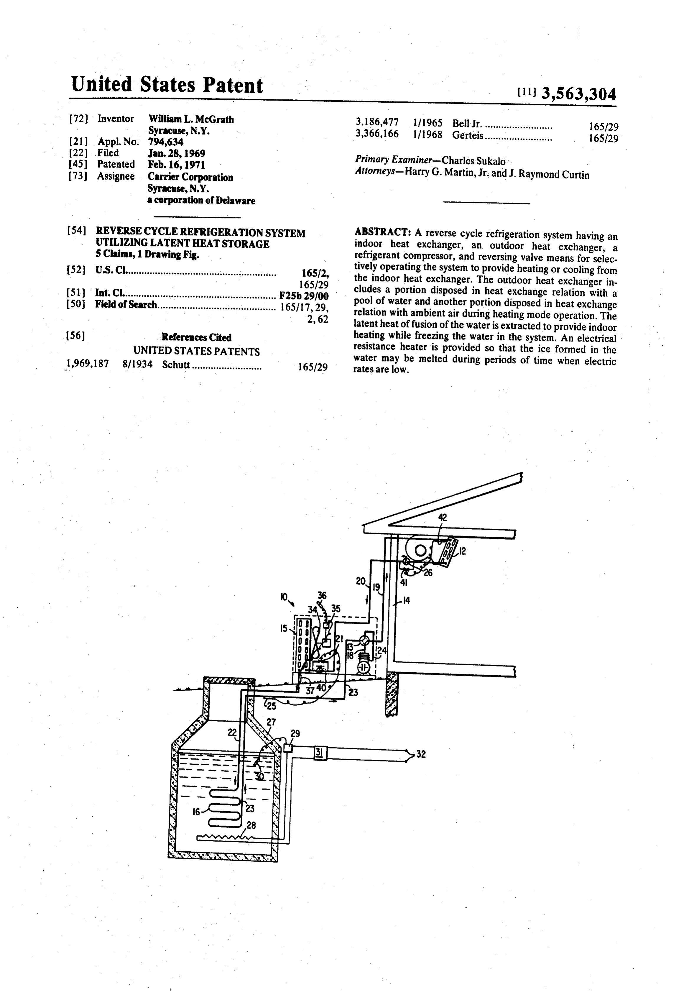
54) REVERSECYCLE REFRIGERATIONSYSTEM ABSTRACT: A reverse cycle refrigeration system having an UTLZNG LATENTHEAT STORAGE indoor heat exchanger, an outdoor heat exchanger, a S Claims, 1 Drawing Fig. refrigerant compressor, and reversing valve means for selec (52) U.S.C....................................................... 16512, tively operating the system to provide heating or cooling from 165/29 the indoor heat exchanger. The outdoor heat exchanger in (51) int. Cli....................................................... F2Sb29/00 cludes a portion disposed in heat exchange relation with a 50 Field of Search............................................ 165/17,29, pool of water and another portion disposed in heat exchange 2, 62 relation with ambient air during heating mode operation. The latent heat of fusion of the water is extracted to provide indoor 56) References Cited heating while freezing the water in the system. An electrical UNITED STATES PATENTS resistance heater is provided so that the ice formed in the 1969,187 8/1934 Schutt.......................... 165129 water may be melted during periods of time when electric rates are low.
Page 2
Drawing sheet — no readable text.
Page 3
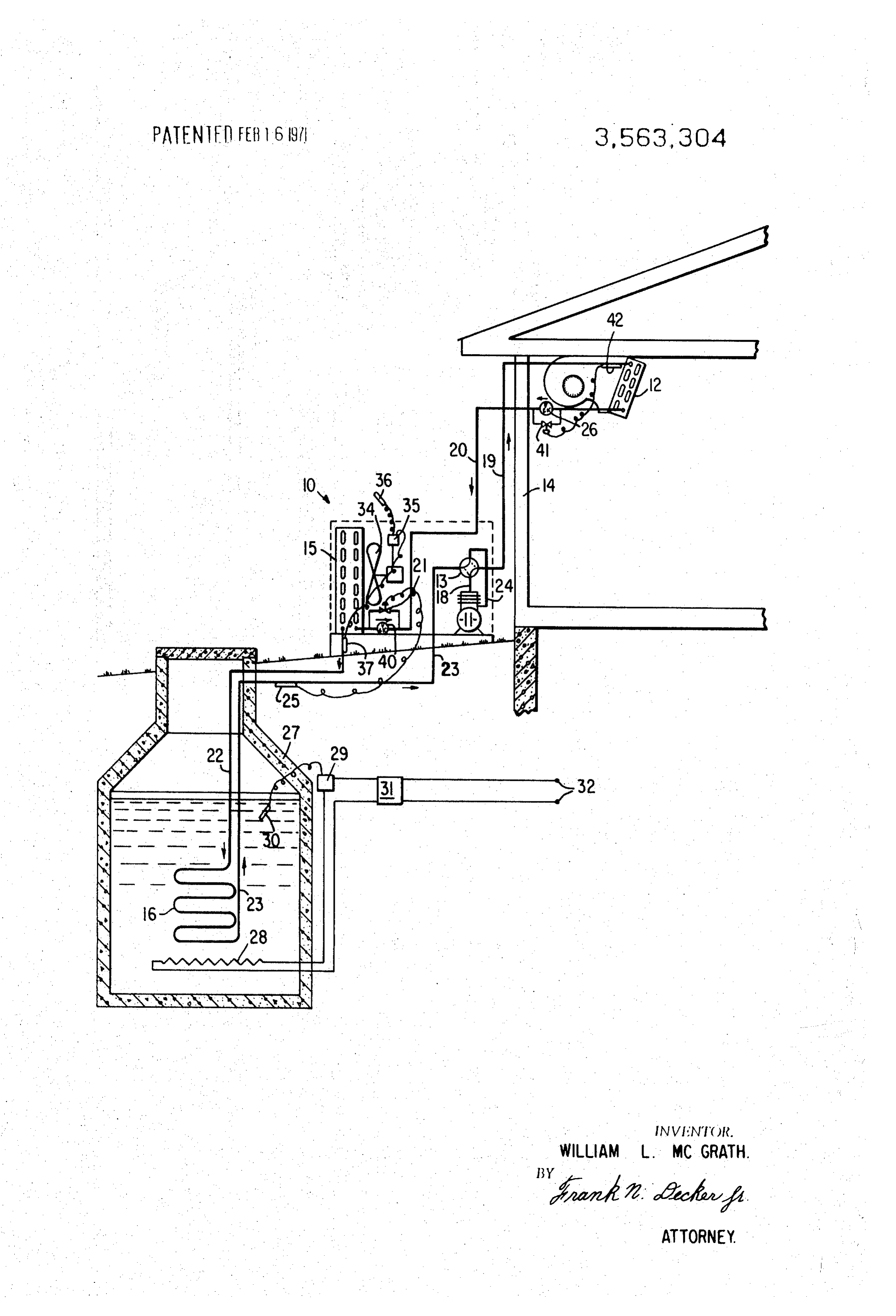
REVERSECYCLE REFRIGERATIONSYSTEM BRIEF DESCRIPTION OF THEDRAWING UTILIZING LATENT HEAT STORAGE The drawing is a schematic illustration of a reverse cycle BACKGROUND OF THE INVENTION refrigeration system partly in cross section utilizing a water Reverse cycle refrigeration systems which may be operated 5 filled tank in accordance with this invention, to provide either heating or cooling at a desired location are DESCRIPTION OF THE PREFERREDEMBODIMENT well known. Prior systems have generally employed an out
Referring to the drawing, there is illustrated a reverse cycle door heat exchanger in heat exchange relation with ambient refrigeration air so that heat is absorbed from the air and pumped to air in- 10 11, a four-waysystem 10 principally comprising a compressor reversing valve 13, an indoor heat exchanger door heat exchanger when indoor heating is desired. While such systems are practical at moderately low ambient tem 12, and an outdoor heat exchanger comprising a first portion peratures, the systems are not entirely satisfactory at very low 15 and a second portion 16. The system is connected to selec ambient temperatures. During severe winter conditions, prior tively provide heating or cooling from indoor heat exchanger reverse cycle systems may be unable to provide satisfactory 15 12 depending on the position of reversing valve 13. heating. The amount of heating which the system can provide As shown in the drawing, reversing valve 13 is in a position is reduced at very low ambient: temperatures, because the to provide heating from the indoor heat exchanger 12. In this capability and efficiency of the system decreases as the tem position, hot gas from compressor 11 passes through hot gas perature lift between the indoor and outdoor heat exchangers passage 18, reversing valve 13 and passage 19 to indoor heat increases. The volumetric efficiency of the compressor 20 exchanger 12. The hot gas is condensed in heat exchanger 12, becomes less as the outdoor temperature drops, thereby thereby giving up heat to a desired location in building 14. reducing the amount of heat transferred between the heat passes The condensed refrigerant from indoor heat exchanger 12 exchangers. In addition, the density of the suction gas is less at through check valve 26 and refrigerant passage 20, low outdoor temperatures which results in a lower volume of through thermal expansion valve 21, to first portion 15 of the refrigerant being pumped and consequently a lower quantity 25 outdoor heat exchanger. The refrigerant then passes from first of heat being transferred. It would be possible to store heat by portion 15 through refrigerant passage 22 to second portion heating water which is in heat exchange relation with the "out 16 of the outdoor heat exchanger where any remaining door heat exchanger" in order to maintain the heat source. refrigerant is evaporated. The refrigerant vapor passes temperature at a high level to overcome the foregoing 30 through refrigerant passage 23, reversing valve 13 and problems. This arrangement however suffers the disadvantage refrigerant passage 24 back to compressor 11. A refrigerant of requiring a large liquid heat storage volume in order to pro bulb 25 is suitably disposed in heat exchange relation with vide heating for an extended period of time because of the refrigerant passage 23 to control refrigerant passage through limited thermal capacity of the water. the outdoor heat exchanger when the system is operating in the heating mode.
SUMMARY OF THE INVENTION 35 Second portion 16 of the outdoor heat exchanger is In accordance with this invention, there is provided a disposed in heat exchange relation with a water-filled tank 27 reverse cycle refrigeration system having an indoor heat which may be buried in the ground or otherwise located as exchanger, an outdoor heat exchanger, a compressor, and a desired. Tank 27 is provided with an electric resistance heater suitable reversing valve. The outdoor heat exchanger com- 40 28 which is connected, through a thermostat 29 and a time prises a portion which is in heat exchange relation with a clock 31, to a source of electric power 32. Thermostat 29 is water-filled cistern or tank and may include another portion provided with a temperature sensing bulb 30 located to sense which is in heat exchange relation with ambient air. A heating the temperature of water or ice in tank 27. means is disposed in heat exchange relation with the water Heat exchanger 15 is in heat exchange relation with the am filled tank and is preferably of an electrical resistance type 45 bient air outside of the building 14. A fan 34 passes air which is connected through a time clock and a thermostatto a through heat exchanger 15. Fan 34 preferably includes an source of electrical power. When it is desired to provide heat electric motor, which is energized by the closing of a dif ing to the indoor coil, at relatively high ambient outdoor air ferential thermostat 35. Differential thermostat 35 may have a temperatures, the system may be operated in a normal heating pair of temperature sensing bulbs including bulb 36 which is mode in which heat is chiefly absorbed by the outdoor heat 0 responsive to ambient air temperature and bulb 37 which is exchanger from the ambient air to evaporate refrigerant. The responsive to temperature of refrigerant leaving heat refrigerant then passes through the portion of the heat exchanger 15. When the difference between the temperatures exchanger in the water-filled tank, is compressed by the com sensed by the two temperature-sensing bulbs drops below pressor, and is condensed in the indoor heat exchanger to pro 55 some predetermined value indicative of a low ambient tem vide heating. As the outdoor temperature drops below the perature, the fan is deemergized. Alternatively, thermostat 55 freezing point of the water, or some other level, less may deemergize fan 35 at a fixed ambient air or refrigerant refrigerant is evaporated in the portion of the outdoor heat temperature such as 32°F.
exchanger which is in heat exchange relation with the ambient In the cooling mode of operation, reversing valve 13 is air and a greater portion of refrigerant is evaporated in the 60 rotated to a position (not shown) such that hot gas from portion of the heat exchanger disposed in the water-filled passage 18 is directed through passage 23 to outdoor heat tank. After a period of time, ice is formed in the tank as the exchangers 16 and 15 respectively. Condensed refrigerant latent heat of fusion of the water is withdrawn to provide heat from heat exchanger 15 passes through check valve 40 and ing to the desired location. thermal expansion valve 41 to indoor heat exchanger 12 The electric resistance heater is energized during periods of 65 where it absorbs heat to provide cooling to building 14. The time when the electric power rate or demand is low in order to evaporated refrigerant passes through refrigerant passage 19, melt ice in the tank. Thus the heat pump system may utilize valve 13 and passage 24 back to the compressor. A tempera low cost power to restore the heat of fusion to the ice. The ture sensing bulb 42 on passage 19 governs passage of volume of the tank need not be as large as prior heat storage refrigerant through thermal expansion valve 31 in the cooling systems because of the relatively high latent heat of fusion 70 mode, available for heating. Furthermore, the heat-cool ratio of the In accordance with this invention, when heating is desired in system is greatly improved by maintaining a minimum outdoor building 14 and the outdoor air temperature surrounding heat heat exchanger evaporation temperature equal to that of the exchanger 15 is above the freezing point of water, fan 34 is freezing point of ice, which results in a relatively higher coeffi energized to pass air over the heat exchanger. The resulting cient of performance in the heating mode than prior systems. T5 heat exchange with ambient air absorbs heat therefrom and
Page 4
evaporates the liquid refrigerant in heat exchanger 15. Any of low ambient operation if desired, by the addition of a suita remaining unevaporated refrigerant passes along with the ble thermal expansion valve and a bypass valve between the refrigerant vapor through heat exchanger 16 in tank 27 where heat exchanger 15 and heat exchanger 16. Likewise, a cascade the unevaporated remainder is vaporized by absorption of arrangement of heat pumps may be utilized with tank 27 being heat from the water in the tank. The refrigerant vapor is then 5 either the heat source of the heat sink for a low pressure heat compressed by compressor 11 and condensed in condenser 12 pump stage depending on the desired conditions of operation to provide heating in the usual manner. of the system.
In the event the ambient air temperature surrounding heat Accordingly, the invention may otherwise be embodied exchanger 15 drops so that an insubstantial portion of 10 within the scope of the following claims.
refrigerant is evaporated in heat exchanger 15, the tempera I claim:
ture difference between bulbs 36 and 37 will decrease and fan 1. A reverse cycle refrigeration system comprising a com 34 will be deemergized. In this event, most of the refrigerant pressor, an indoor heat exchanger, a first outdoor heat exchanger, a second outdoor heat, exchanger, refrigerant ex will leave heat exchanger 15 in a liquid state and pass through passage 22 to heat exchanger 16 in the tank. The liquid 15 tion pansion means and reversing means connected in a refrigera refrigerant will then absorb the heat from the water in the tank refrigerant circuit for selectively providing heating by condensing 27 and be evaporated in heat exchanger 16. Since heat is in the indoor heat exchanger and evaporating being absorbed from the water in the tank, the water will even refrigerant in the outdoor heat exchangers; a tank containing a freezable liquid; said first outdoor heat exchanger being tually freeze forming ice as it gives up its latent heat of fusion. disposed in heat exchange relation with the freezable liquid in In effect, when the ambient temperature decreases below the 20 freezing point of water, the latent heat of fusion of the water said tank; said second outdoor heat exchanger being disposed will be utilized as the heat source to provide heating to build in heat exchange relation with ambient air; passage means disposed to pass condensed refrigerant from the indoor heat ing i4.
The time clock 31 controlling electric resistance heater 28 exchanger serially through said second outdoor heat is arranged so that power may be supplied to the heater during 25 exchanger and then through said first outdoor heat exchanger for absorption of heat first from the ambient outdoor air and periods of time when electric power rates or demand are at a thereafter minimum. This is advantageous in many locations where elec from the freezable liquid in said tank when said tric utilities offer lower power rates during periods of time system is arranged for providing heating from said indoor heat exchanger; fan means for passing ambient air over said second when electric power consumption is at a minimum, or exact a outdoor heat exchanger in heat exchange relation with charge based on the maximum power demand required. 30 refrigerant therein for evaporating said refrigerant when the
When bulb 30 of thermostat 29 senses a temperature in tank system is providing heating from the indoor heat exchanger; 27 at or below the freezing point of water, the thermostat wherein the improvement comprises control means for con closes to energize electric heater 28 and time clock 31 trolling the operation of said fan, said control means having a completes the circuit providing preferential power rates are in first effect. While the time clock has been shown for purposes of il 35 ture temperature sensor disposed for sensing a first tempera lustration, it will be apparent that other current switching second heat exchangertemperature comprising the of refrigerant leaving the and passing to the first heat exchanger, devices, such as a carrier current operated relay may be util ized in response to an appropriate signal indicating that said control means being arranged to energize said fan when preferential power rates are in effect either due to reduced 40 ceeds a second sensed the temperature by said first temperature sensor ex temperature so that the refrigerant is utility rates or low additional power demand by the user. evaporated in the second outdoor heat exchanger to absorb Operation of electric heater 28 will melt any ice in tank 27 substantial heat from the ambient air, said control further and raise the temperature of the water therein to any desired being arranged value. It is not desirable, however, to raise the temperature of sensed by said tofirst deemergize said fan when the temperature water in tank 27 appreciably above the freezing point because 45 second temperature sotemperature that the sensor drops below said refrigerant is evaporated in the heat loss from the tank would be excessive in comparison to first outdoor heat exchanger to remove substantial latent heat the amount of heat which could be withdrawn by sensible cooling of water during heating mode operation. For example, of fusion from and freeze the liquid in said tank, and heating means for raising the temperature of liquid in said tank slightly the available latent heat of fusion of the ice is about 144 B.t.u.
per pound while raising the temperature of the water all the 50 above the freezing temperature of the liquid therein at desired way to the boiling point would only provide about 180 B.t.u. periods of time.
2. A reverse cycle refrigeration system as defined in claim 1 per pound and would result in excessive heat loss from the wherein said system includes a second temperature sensor for storage reservoir. sensing said second temperature, said second temperature From the foregoing, it will be seen that utilization of latent sensor being disposed to sense the temperature of ambient air; heat of fusion as a heat source for the heat pump results in a 55 said control means including a differential thermostat respon number of substantial advantages over prior systems. For ex ample, the size of tank may be relatively small for a given sive to the difference between said first and second tempera tures for energizing said fan when said differences in tempera amount of heat in comparison with a heat storage reservoir tures is relatively large and for deemergizing said fan when said which utilizes sensible cooling of water to provide heat. difference in temperatures is relatively small to thereby selec Furthermore, until all of the water in the tank is frozen to solid 60 tively absorb heat from either ambient air or liquid in said tank ice, minimum refrigerant evaporation temperature in the depending on said difference in temperatures. system is maintained at 32 F, thereby preventing excessively 3. A method of operating a reverse cycle refrigeration high lift across the compressor. This in turn results in a high system having a compressor, an indoor heat exchanger, a refrigeration cycle efficiency and provides a high coefficient liquid-filled tank, heating means disposed in heat exchange of performance when operating the system in the heating 65 relation with the liquid in the tank, a first outdoor heat mode. In addition, a reverse cycle refrigeration system in ac exchanger disposed in heat exchange relation with the liquid cordance with this invention provides an improved heating-to in the tank, a second outdoor heat exchanger disposed in heat cooling ratio for a given size system which is desirable for exchange relation with ambient air and refrigerant expansion providing heating in colder climates. At the same time, it will means, said method comprising:
be appreciated that the utilization of low cost electric power 70 a. passing refrigerant vapor to the compressor and com or reduction of demand charges improves the economy of this pressing the vapor therein; system. b. passing compressed vapor from the compressor to the in Various modifications of the invention may be made door heat exchanger and condensing the compressed without departing from the scope thereof. For example, heat refrigerant in the indoor heat exchanger to provide heat exchanger 15 may be utilized as a subcooler during conditions 75 ing to a desired location;
Page 5
c. freezing liquid in the tank and absorbing substantial latent proportion of condensed refrigerant passed to said first heat of fusion of the liquid therefrom by evaporating a sub exchanger by controlling passage of ambient air over said stantial portion of the condensed refrigerant in said first second heat exchanger in response to the temperature of outdoor heat exchanger when the ambient air tempera refrigerant passing from said first outdoor heat exchanger to ture is relatively low, and absorbing substantial heat from said second outdoor heat exchanger. the ambient air by evaporating a substantial portion of the 5. A method of operating a reverse cycle refrigeration condensed refrigerant in said second outdoor heat system as defined in claim 4 including a step of controlling the exchanger when the ambient temperature is relatively passage of ambient air over said second heat exchanger in high; and d. melting frozen liquid in the tank by heating the frozen 10 response to the difference in temperature between said am. liquid to restore the latent heat of fusion to the liquid in bient air temperature and the temperature of refrigerant the tank when desired. passing from said first outdoor heat exchanger to said second 4. A method of operating a reverse cycle refrigeration outdoor heat exchanger.
system as defined in claim 3 including the step of varying the
Provenance
- Collection
- Cited prior art
- Original PDF
- patentimages.storage.googleapis.com →
- Filed
- 1969-01-28
- Pages
- 5
- Method
- pdftotext (the PDF's own text layer) + pdftoppm 300dpi page scans
- Source
- Google Patents bibliographic record
- Granted
- 1971-02-16
- Inventors
- William L Mcgrath; Carrier Corp
- Transcribed from
- patentimages.storage.googleapis.com →