patent · US4392531
Earth storage structural energy system and process for constructing a thermal storage well
12 July 1983
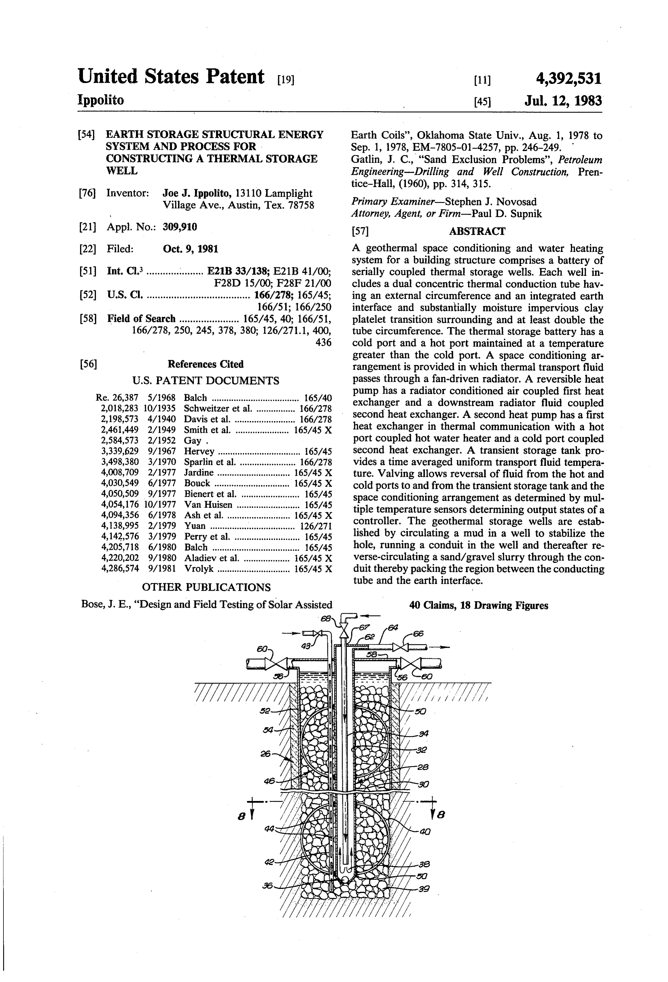
Page 1 — bibliographic record
United States Patent (19) (11) 4,392,531 Ippolito 45 Jul. 12, 1983 54 EARTH STORAGE STRUCTURAL ENERGY Earth Coils', Oklahoma State Univ., Aug. 1, 1978 to SYSTEM AND PROCESS FOR Sep. 1, 1978, EM-7805-01-4257, pp. 246-249. CONSTRUCTING ATHERMAL STORAGE Gatlin, J. C., "Sand Exclusion Problems', Petroleum WELL Engineering-Drilling and Well Construction, Pren
76 Inventor: Joe J. Ippolito, 13110 Lamplight Primary Examiner-Stephen J. Novosad Village Ave., Austin, Tex. 78758 Attorney, Agent, or Firm-Paul D. Supnik (21) Appl. No.: 309,910 57 ABSTRACT (22 Filed: Oct. 9, 1981 A geothermal space conditioning and water heating system for a building structure comprises a battery of 51 Int. Cl...................... E21B33/138; E21B 41/00; serially coupled thermal storage wells. Each well in F28D 15/00, F28F 21/00 cludes a dual concentric thermal conduction tube hav 52 U.S. Cl. ...................................... 166/278; 165/45; ing an external circumference and an integrated earth 166/51; 166/250 interface and substantially moisture impervious clay 58 Field of Search ...................... 165/45, 40; 166/51, platelet transition surrounding and at least double the 166/278, 250, 245, 378, 380; 126/271.1, 400, tube circumference. The thermal storage battery has a 436 cold port and a hot port maintained at a temperature greater than the cold port. A space conditioning ar (56) References Cited rangement is provided in which thermal transport fluid
Re. 26,387 5/1968 Balch .................................... 165/40 pump has a radiator conditioned air coupled first heat 2,018,283 10/1935 Schweitzer et al. ... 66/278 exchanger and a downstream radiator fluid coupled 2, 198,573 4/1940 Davis et al. ..... ... 166/278 second heat exchanger. A second heat pump has a first 2,461,449 2/1949 Smith et al. ...................... 165/45 X heat exchanger in thermal communication with a hot 2,584,573 2/1952 Gay . port coupled hot water heater and a cold port coupled 3,339,629 9/1967 Hervey .................................. 65/45 second heat exchanger. A transient storage tank pro 3,498,380 3/1970 Sparlin et al. ... ... 166/278 vides a time averaged uniform transport fluid tempera 4,008,709 2/1977 Jardine ........ ... 165/45 X ture. Valving allows reversal of fluid from the hot and 4,030,549 6/1977 Bouck ............................... 165/45 X cold ports to and from the transient storage tank and the 4,050,509 9/1977 Bienert et al. ........................ 165/45 space conditioning arrangement as determined by mul 4,054,176 10/1977 Van Huisen .......................... 165/45 tiple temperature sensors determining output states of a 4,094,356 6/1978 Ash et al. .......................... 165/45 X 4,138,995 2/1979 Yuan ........... ... 126/271 controller. The geothermal storage wells are estab 4,142,576 3/1979 Perry et al. ........................... 165/45 lished by circulating a mud in a well to stabilize the 4,205,718 6/1980 Balch .................................... 165/45 hole, running a conduit in the well and thereafter re 4,220,202 9/1980 Aladiev et al. ................... 165/45 X verse-circulating a sand/gravel slurry through the con 4,286,574 9/1981 Vrolyk .............................. 165/45 X duit thereby packing the region between the conducting tube and the earth interface.
OTHER PUBLICATIONS
Bose, J. E., “Design and Field Testing of Solar Assisted 40 Claims, 18 Drawing Figures
Page 2
Drawing sheet — no readable text.
Page 3
Drawing sheet — no readable text.
Page 4
Drawing sheet — no readable text.
Page 5
Drawing sheet — no readable text.
Page 6
Drawing sheet — no readable text.
Page 7
Drawing sheet — no readable text.
Page 8
Drawing sheet — no readable text.
Page 9
moisture impervious clay platelet transition surround
EARTH STORAGE STRUCTURAL ENERGY ing the central thermal conduit. The ratio of the surface SYSTEM AND PROCESS FOR CONSTRUCTING A area of the clay platelet transition to the central thermal THERMAL STORAGE WELL conduit surface area is at least about two to one, thereby enhancing the effective heat transfer by improving con
BACKGROUND OF THE INVENTION duction into the earth.
1. Field of the Invention In a more specific example, the warmer port is cou This invention relates to residential and commercial pled to a domestic water supply preheater and a water heating and cooling systems. More particularly, the 10 heater, and a heat pump coupled between the hot water invention relates to systems ultilizing geothermal well heater and the cool port returns heat pump coolness to energy storage. the wells.
2. Description of the Prior Art Additional features in accordance with the invention In the past, earth coupled heat pump systems have include concentric conduit within each well for circu proved technically successful, but economically unat lating a thermal transfer fluid. A water source coupled tractive, as a result of high initial capital requirements 15 slotted pipe adjacent outer conduit in each well main and operating costs. Typical systems have traditionally tains moisture within the wells. Centralizers support the been made up of buried arrays of pipes and some using thermal transfer conduit centrally within the wells. The standard wells. Buried array systems have had limited wells may be disposed in a line source array, or point free surface area and limited access for repair. Both 20 source arrays. Preferably, the wells are at a high angle standard type wells and buried array systems have en for significant thermal interchange with the earth. countered problems with low conductivity in dry soil Other features include a control valve for redirecting and reduced transport capacitance following several the porting of hot and cold fluid from the array. Valv heating and cooling cycles. It has been demonstrated ing is provided for bypassing hot port originating ther that earth coupled systems where high ground water mal transport fluid to a transit storage tank, for direct exists have functioned better when withdrawing energy 25 ing and bypassing a secondary heat exchanger or solar from the ground than when storing thermal energy. collector, and for bypassing the radiator. Earth coupled systems have been effective in collect A method for drilling wells in according to this in ing heat from areas with high ground water and induc vention generally comprise the steps of drilling a well to ing freezing around the pipe. This has insured no free a well depth, circulating a mud to stabilize the hole and space between pipe and ground, and therefore allows 30 establish a thick filter cake and a rock face transition, conduction as opposed to radiation being the thermal and running an outer thermal conduit in the hole. A transport mechanism. Attempts to use the earth as a sand/gravel mixture is packed by circulation of a slurry heat sink in warmer environments have been less suc cessful due to drying of the rock around the pipe with between the filter cake and the outer thermal conduit. Additional steps in accordance with the method include the associated reduction in thermal conductivity and 35 the void areas where the pipe has lost physical contact running a slotted pipe in the hole. Pumps are coupled to with ground. This is usually introduced by the constant accessfilter ports to pump water and mud through the well. expansion and contraction of pipe with heating and The cake transition is built up by reverse circulat cooling. The temperature changes produce these gaps ing drilling mud down the outside of the thermal trans through the expansion of the pipe, compaction of 40 fer conduit and up through the center of the conduit. ground, followed by contraction of the pipe with cool thisA invention different example of a method in accordance with involves the running of a second smaller ing. If this volume contains only air then thermal trans tube into the well port is very small. While there has been the use of a drip includes pumpingoutside a of the outer tube. The method sand/gravel slurry down the well source to attempt the moistening of the surroundings, most systems have been limited to using the earth as a 45 to through the small diameter tube and allowing the fluid heat source only and therefore increasing the required return through the access ports. surface area several orders of magnitude. BRIEF DESCRIPTION OF THE DRAWINGS SUMMARY OF THE INVENTION The nature of the invention described herein may be A structural energy system in accordance with this 50 best understood and appreciated by the following de invention generally comprises an earth storage array scription taken in connection with the accompanying. having a first and second ports coupled to a space con drawings in which:
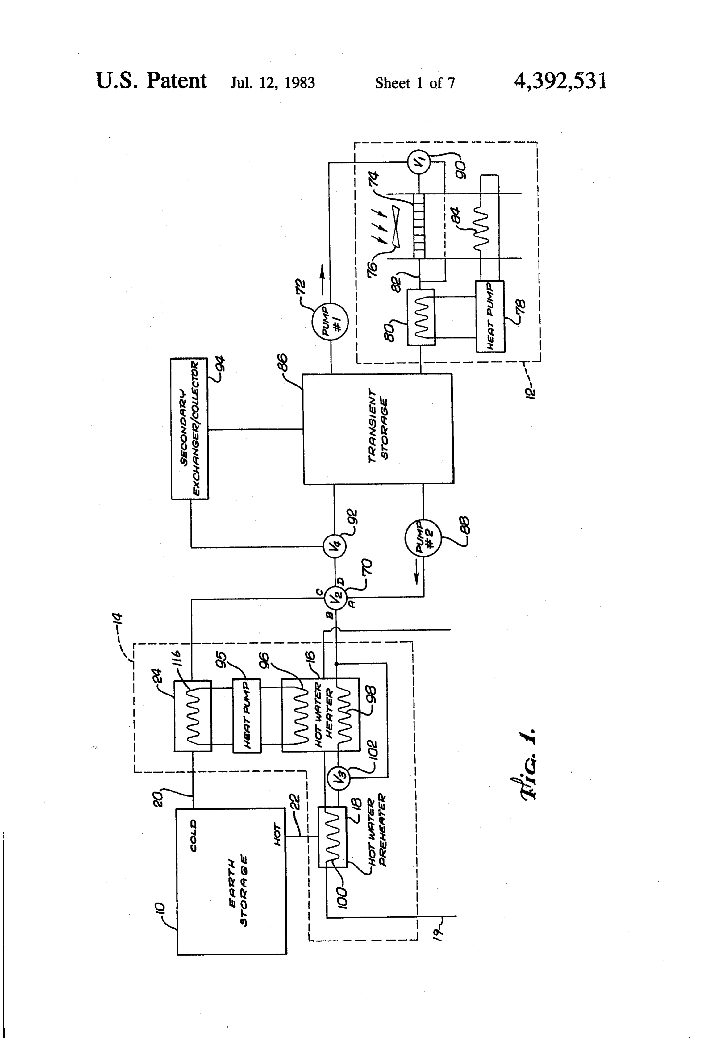
ditioning system for the structure. The space condition FIG. 1 is a diagrammatic view of an example of a ing system includes a heat pump and radiator for rein structural energy system in accordance with this inven forcing the effectiveness of the heat pump by reducing 55 tion;
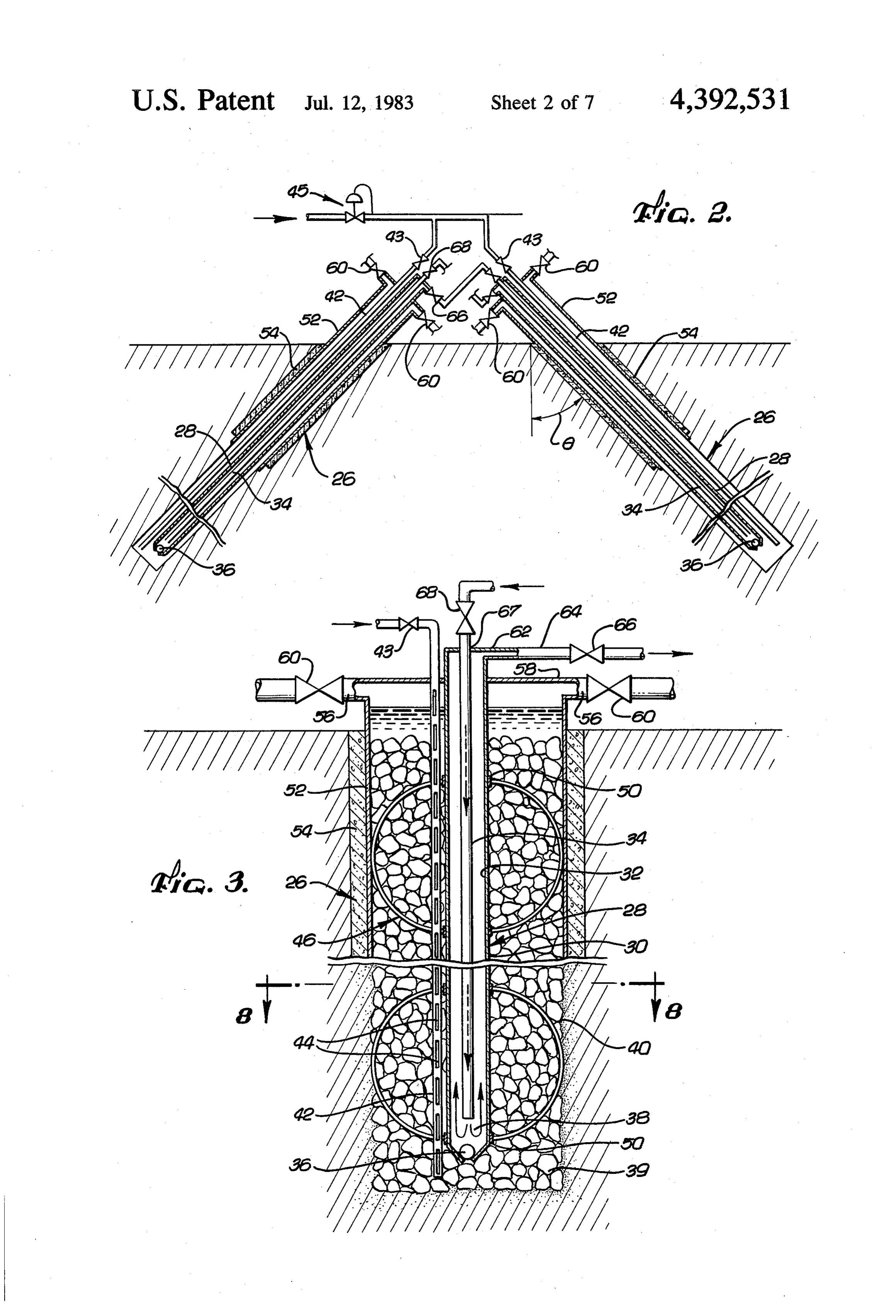
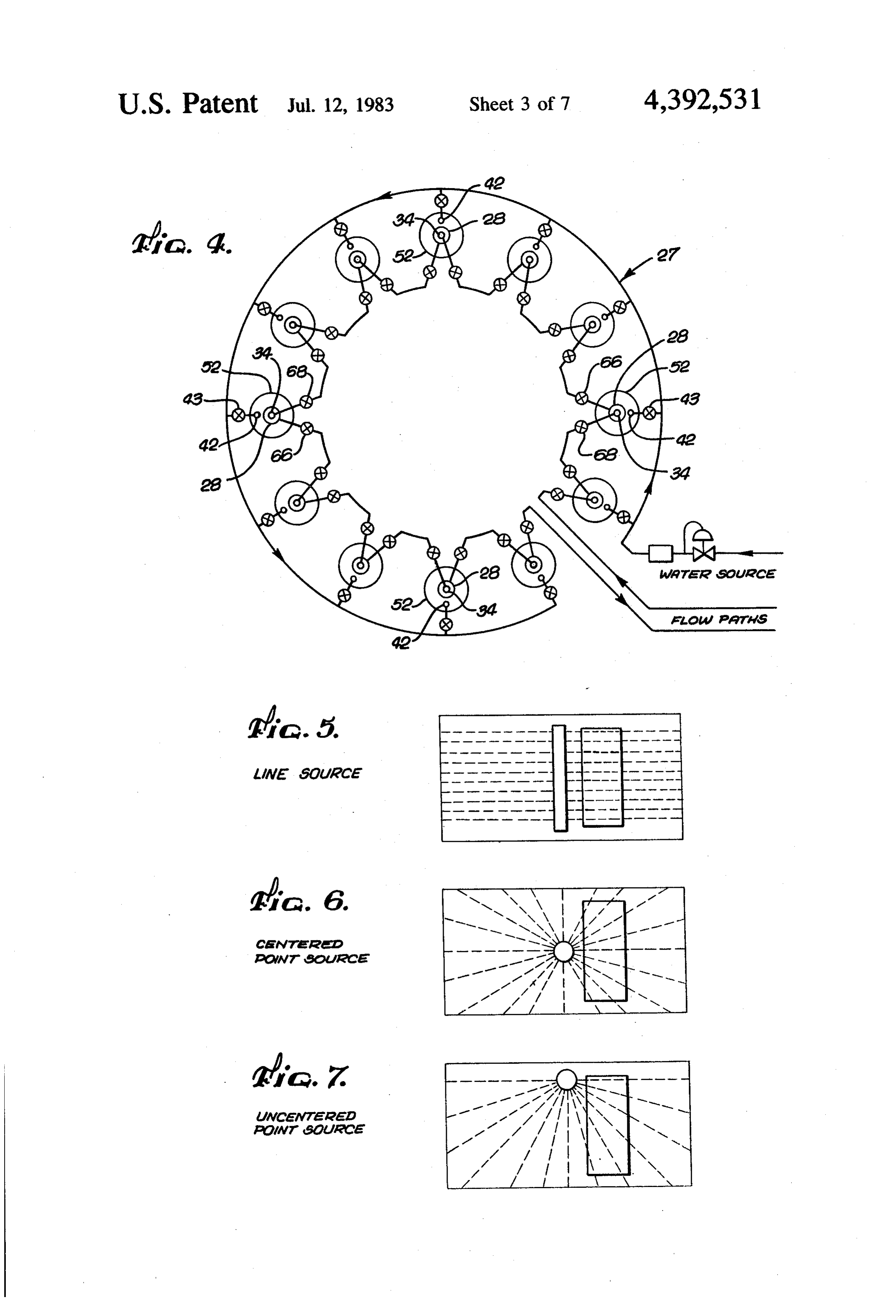
the temperature differential over which the heat pump FIG. 2 is a cross-sectional view with portions ex operates, in heating and cooling modes, and by appro posed and portions removed of an example of a well priately rechanneling relatively warm or cool heat array in accordance with this invention; transport fluid to the appropriate hot or cold ports of FIG. 3 is a detailed cross-sectional view of a single the earth storage array. 60 well of a well array in accordance with this invention The earth storage array, in accordance with this in with portions exposed and portions removed; vention comprises an effectively elongated storage well FIG. 4 is a diagrammatic view of the serial coupling arrangement. The array is coupled to the system in such of a point source well array in accordance with this a manner as to maintain a unidirectional temperature invention;
gradient between the ports, so that the first port is al 65 FIG. 5 is a diagrammatic plan view of a line source ways at a warmer temperature than the second port. array in accordance with this invention; Each well in accordance with the invention comprise FIG. 6 is a diagrammatic plan view of a centered a central thermal transfer conduit and a substantially point source array in accordance with this invention;
Page 10
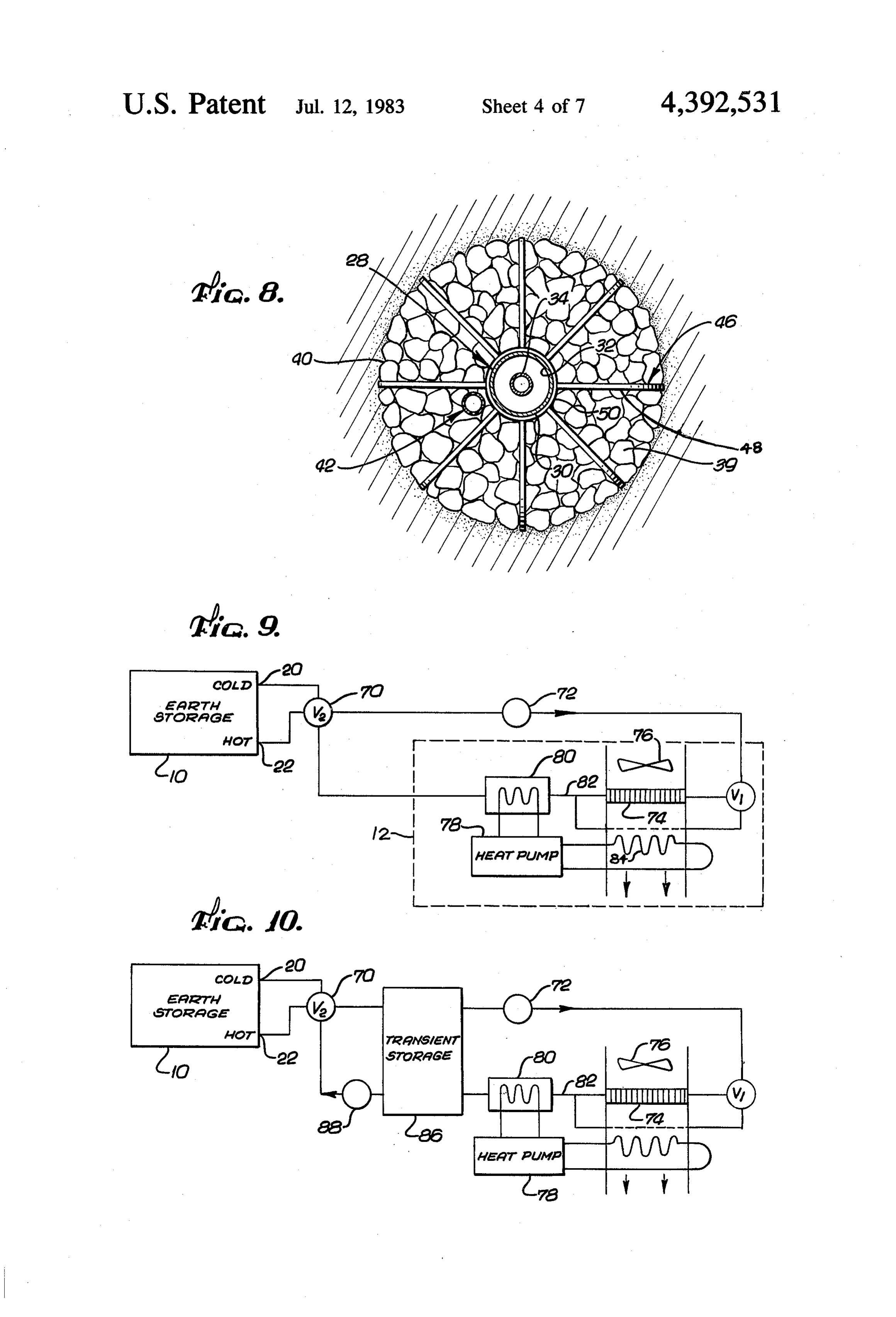
FIG. 7 is a diagrammatic plan view of an eccentric an acute angle 6 to the vertical. Typically, 6 is between point source array in accordance with this invention; about 20' to 45°. The angle 6 provides for the spacing FIG. 8 is a cross-sectional detail view of the well in accordance with this invention taken along lines 8-8 of depthcollection and and volume of geothermal energy. It allows the storage qualities of the earth to be
FIG. 3; 5 utilized, while the horizontally projected spread of the FIG. 9 is a diagrammatic block diagram of a different example of an structural energy system in accordance array limits interference between wells and spreads the vertically directed heat migration of the wells over a with this invention; greater area. The minimum 6 is determined to avoid FIG. 10 is a diagrammatic block diagram of a differ significant well intereference, and the maximum 8 is ent example of a structural energy system in accordance 10 limited by the available lot surface area and the practi with this invention;
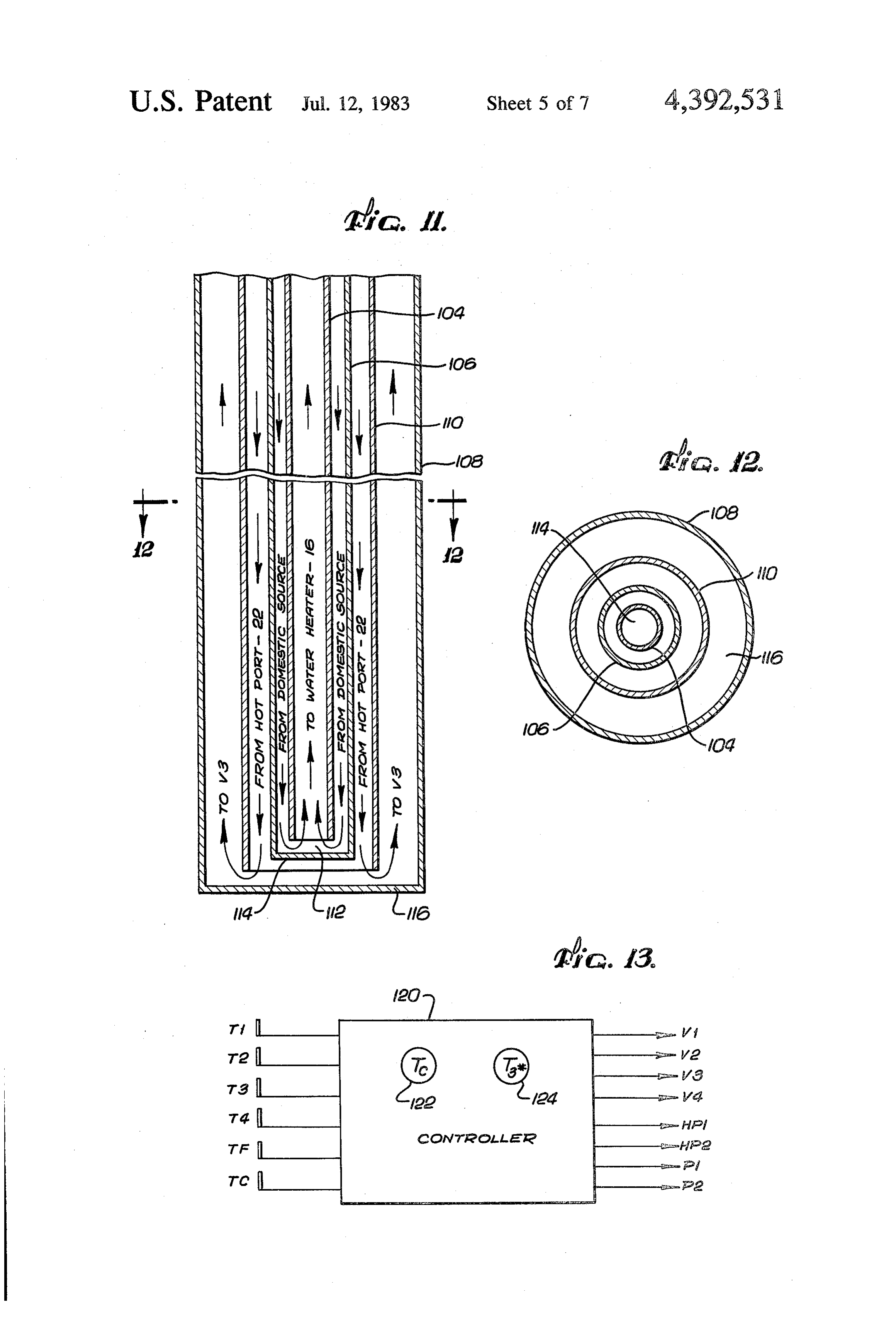
FIG. 11 is a diagrammatic perspective view of a por horizontal. Additionally, it isstrings cality of supporting drilling at small angles to the generally not desirable to tion of a preheater in accordance with this invention; have any significant portion of the well within about 3 FIG. 12 is a cross-sectional view of the preheater meters from the earth's surface as this region tends to be taken along lines 12-12 of FIG. 11; 15 maintained close to the average ambient temperature. FIG. 13 is a diagrammatic view of a controller in The array may consist of a line source array, shown accordance with the invention;
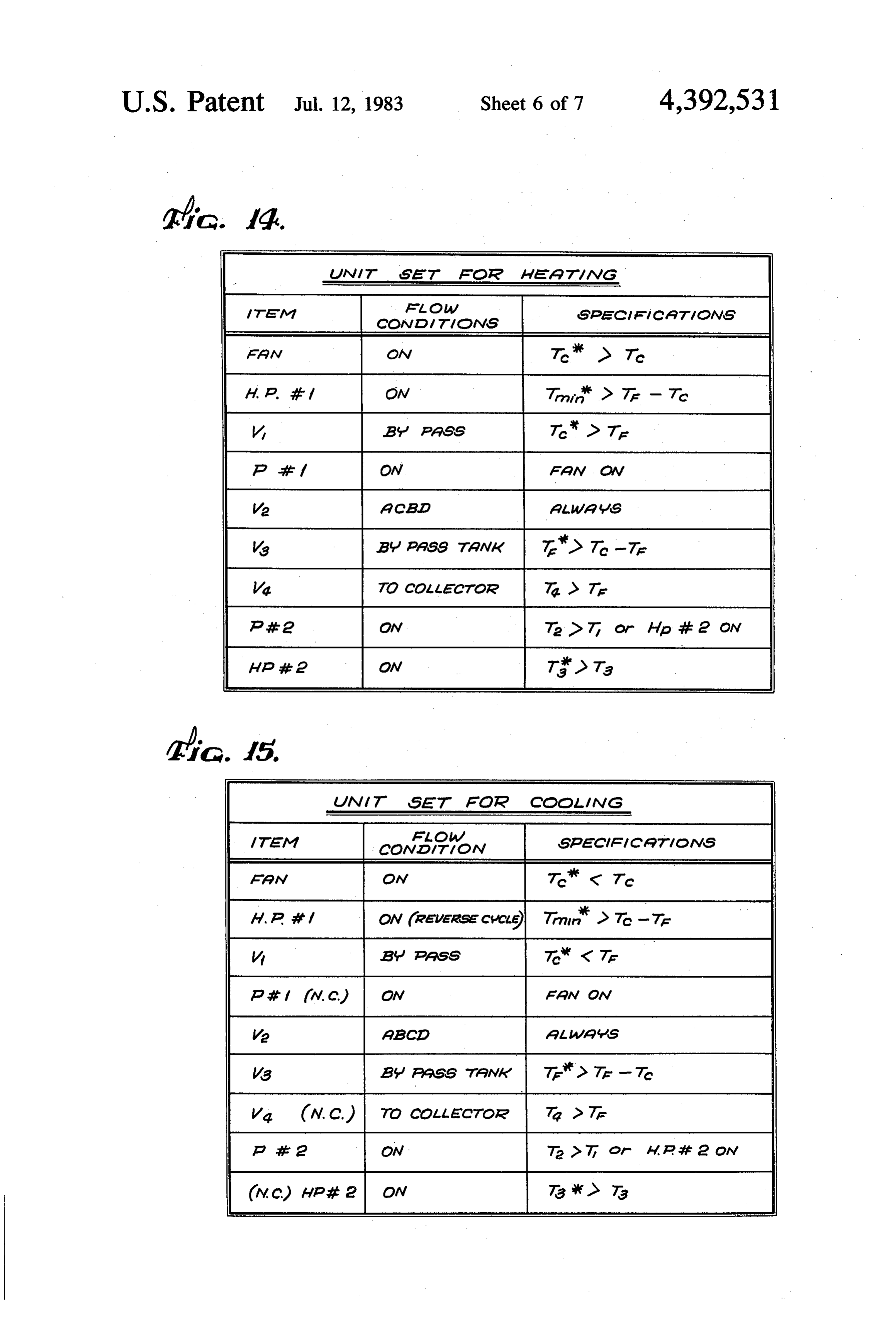
FIG. 4 is a logic chart depicting conditions and schematically shown in FIG. 5, a centered point source array, schematically in FIG. 6 or an uncentered point states of the controller of FIG. 13 in a heating mode, in source array, shown schematically in FIG. 7. It should accordance with this invention; 20 also be recognized that in some arrangements, trenches FIG. 15 is a logic chart depicting conditions and may be made in the earth, and conduit may be placed states of the controller of FIG. 13 in a cooling mode in horizontally in the trenches. accordance with this invention; An outer tube or longitudinal conduit 28 is disposed FIG. 16 is a block diagram of a method for making centrally within the thermal storage wells in accordance with this invention; 25 outer surface 30 and well 26. The outer tube 28 has an an inner surface 32. An inner tube
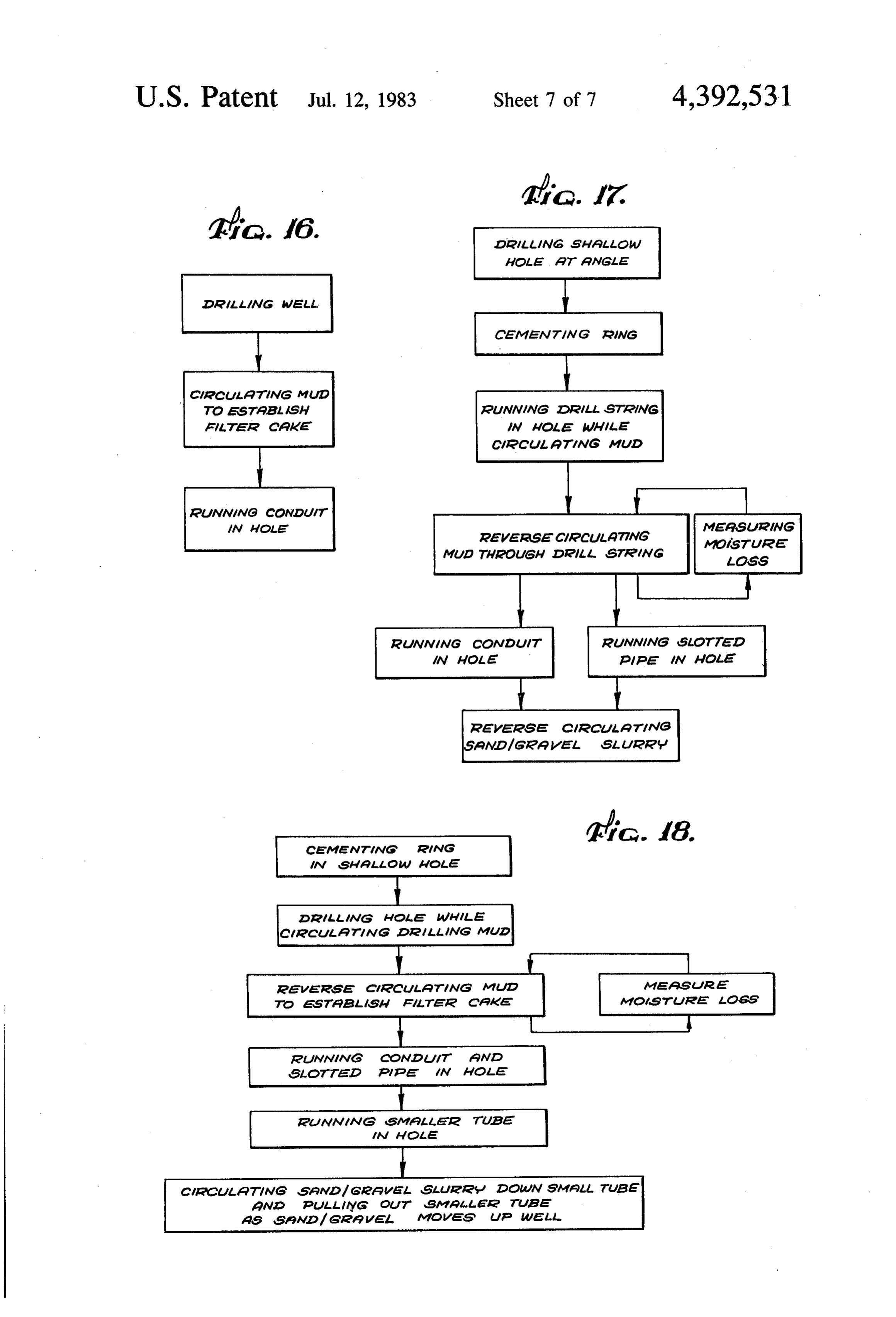
FIG. 17 is a block diagram of the method depicted in or longitudinal conduit 34 is disposed within the outer FIG. 16; and
FIG. 18 is a block diagram of another example of a tube 28 and concentric therewith. A lower portion of method for making a thermal storage well in accor bottom oftubethe outer 28 is spaced apart somewhat from the the well 26. At the bottom of the outer tube dance with this invention. 30 28, a check valve 36 or one way valve allows flow only DETAILED DESCRIPTION from pressure exerted from outside the tube 28 but not down and out the tube 28. This check valve 36 aids in
With particular reference to FIG. 1, an example of a constructing the well 26, yet when in operation, pre structural energy system in accordance with this inven vents escape of fluid. The inner tube 34 and the outer tion generally comprises an earth storage arrangement 35 tube 28 provide a flow path for passing fluid actively 10, a space conditioning arrangement 12 and a hot water through the well 26. A transfer region 38 between the heating arrangement 14. The earth storage arrangement check valve 10, space conditioning arrangement 12 and the hot provides for a36return and the bottom of the inner tube 28 flow path from one of the tubes 28, water heating arrangement 14 are coupled through a pumping and valving arrangement as will be described 34 to the other. It may be desirable to plug the check valve 36 after construction to avoid reverse flow to the in greater detail, for selectively directing thermal trans system.
port fluid through the system. Note that additional transportThis could possibly occur if the flow of thermal fluid were stopped, creating greater pressure examples of systems in accordance with this invention outside of the conduit. A heavier check valve ball may are diagrammatically depicted in FIGS. 9 and 10. The system depicted in FIG. 1 utilizes a hot water heater 16 45 alsoA be utilized to avoid this problem. coupled to a hot water preheater 18 for raising the surface 30 of thevolumetric particulate outer tube mass 39 surrounds the outer 28. The particulate volumet temperature of water entering the system from a domes ric mass 39 is typically gravel or a combination of sand tic water source 19.
and gravel. At the outer surface
The earth storage unit has a cold port 20 and a hot stantially moisture impervious integrated of the well 26, a sub port 22. A heat exchanger 24 is coupled to thermally 50 exists and the particulate volumetric massinterface 39
extends communicate with the cold port 20, and the hot port 22 is coupled to thermally communicate with the hot adjacent platelets the interface 40. The interface 40 comprises of clay such as bentonite. This results from the water preheater 18.
The earth storage unit 10 is coupled to the system so tion of the wells 26.fluids clay based drilling
The which are used in the construc interface may also consist, to as to enhance the temperature differential existing at 55 various extent of the following any point in time between the cold port 20 and the hot tannins, lignosulfonates, sodiummaterials, such as lignins carboxymethycellulose port 22. At any point in time, the temperature at the and acrylonitrile, which act as thinners for the clay cold port 20 is colder than the temperature at the hot drilling fluids. These compounds are selected to help port 22, as will be explained below. In cooling modes, heat is generally supplied to the hot port 22 for storage build a structural filter cake against the rock face of the earth. Over a period of time, platelets impact against the and coolness may be returned from the cold port 20. rock face, enhancing the structural integrity of the well The building structure may require at any point in time 26, during its construction, and build a semipermeable relatively cooler thermal exchange or relatively wall preventing significant loss of moisture from the warmer thermal exchange and the system provides for well 26 when in operation.
obtaining this on demand. 65 An apertured conduit or pipe 42 having spaced apart The earth storage arrangement 10 is best viewed in slots or apertures 44 is disposed within the well adjacent FIGS. 2, 3 and 4. It comprises an array 27 of wells 26 the outer tube 28. The apertured pipe 42 provides a disposed within the earth, generally at a high angle or means of moisturizing the particulate mass 39 to main
Page 11
tain thermal conduction between the outer conduit 28 cold tempering fluid. The control valve 70 is coupled to and the surrounding earth rather than allow air filed a pump 72 (P2) circulating thermal transport fluid. The gaps, which would otherwise result in solely thermal control valve 70 is coupled so that it may gate either radiation and high thermal resistance. A valve 43 ports relatively warm thermal transport fluid, originating domestic water source to the apertured pipe 42, and a from the hot port 22 or colder thermal transport fluid pressure controller 45 coupled to the valve 43 maintains originating from the cold port 20, to pass through and a constant but limited pressure to the particulate mass be circulated by the pump 72 though the space condi 39. tioning arrangement 12 of the system. To maintain the inner and outer tubes 28, 34 within A radiator 74 is serially coupled to the pump 72 so the center of the well, centralizers 46, as best viewed in 10 that either warm or cold fluid from the pump passes FIGS. 3 and 8, are spaced apart on the exterior of the through the radiator 74. If the transport fluid passing tubes. The centralizers 46 have a plurality of semi-circu through the radiator 74 is cooler than the ambient room lar fingers 48 extending radially between and coupled to temperature, then the radiator 74 will tend to reduce the a pair of spaced apart central hubs 50 to maintain the room air temperature. If the transport fluid is warmer, tubes 28 in position during construction of the wells 26. 15 then the radiator 74 will tend to increase the room air A surface pipe 52 is disposed on an upper portion of temperature. A fan 76 is coupled to increase the thermal the well 26, and is surrounded and maintained in place transfer between the radiator and the ambient air. As by a surface cement ring 54 which surrounds the surface the air is either warmed or cooled by the radiator 74, the pipe 52. thermal transport fluid in the radiator 74 is cooled or Access ports 56 extend outwardly from the surface 20 warmed, respectively by ambient and forced air of the pipe 52 of the well 26. The access ports 56 permit the fan 76. This system advantageously utilizes even only expulsion of drilling mud during the process of con moderately warm or cool thermal transport fluid when structing the well. Water or drilling muds are used as warmer or cooler than ambient air to raise or lower the drilling fluids. room air temperature.
The water from the drill string passes on the insides 25 When greater heating or cooling function is required of the drilling pipe and the fluid exits at the access ports than can be supplied by the fan 76 and the radiator 74, 56. With the total depth reached, a water base drilling a space conditioning heat pump 78, coupled from a heat mud is circulated down the inside of drill pipe and out exchanger 84 to the ambient air in the vicinity of the access ports 56 to stabilize the hole. The drilling mud radiator 74 to a return heat exchanger 8 coupled to a forms a filter cake 40 and preserves the structural integ 30 return fluid conduit 82, provides such enhancement. It rity of the hole. The drill string is removed and the should be recognized that the fan 76 is coupled in series outer tube 28 is put in place with centralizer 46 at with the radiator 74 and the heat exchanger 84. In some tached. The sand and gravel slurry are then pumped configurations, a separate fan may be used for forced into place. convection across the heat exchanger 84. The heat ex A cover 58 provides for a closed pressurizable sys 35 changer 80, then can be used to reinforce and enhance tem. It is possible also to use the access pipes 56 as a the function of the radiator 74, by either aiding in the air means for providing moisture to the well center, instead heating function or the air cooling function, depending of the apertured pipe 42, though the apertured pipe is on the operating phase of the system. During cooling preferable. Escape valves 60 are coupled to the access cycles, energy is then "transported' from the ambient pipes 56 to selectively allow access and removal of 40 air to the return heat exchanger 80, to be absorbed by fluids and slurries to and from the well 26. the transport fluid from the return conduit 82. During The cover 58 maintains fluid closure of the well 26, heating, energy is then "transported" from the transport and is disposed above the surface pipe 52. The outer fluid in the heat exchanger 80 to the ambient air. Since tube 28 extends upwardly through the well cover 62 the radiator 74 brings the temperature close to the tem and a coupling pipe 64 extends therefrom, coupled to an 45 perature desired, the heat pump 78 requires the input of access valve 66. The access valve 66 permits flow only limited energy to drive the air to the desired tem through the interior of the outer tube 28. The inner tube perature.
34 extends through the upper portion of the outer tube Moreover, since both the exhaust of the heat pump 78 28 at aperture 67. An access valve 68 is coupled to also and the radiator 74 passed fluid are combined in the heat permit the flow of the thermal transport fluid. 50 exchanger 80, that fluid may become warmer or colder The valving and serial coupling of the well array or than the temperatures spanned at the ports 20, 22 of the battery 27 of the earth storage arrangement 10 is shown earth storage arrangement 10. The valve 70 may then schematically in FIG. 4. A fluid transport flow path is gate the fluid, depending on the temperature, to either provided by coupling each outer tube 28 of each well 26 the cold 20 or hot 22 port to thereby store the energy. to the inner tube 34 of the adjacent well 26. The result 55 Thus, if the temperature of the return fluid is greater is a serial flow path, which in effect enhances the effec than the temperature of the hot port 22, the fluid may be tive length of the well. The fluid flow path so obtained gated to the hot port 22, and ifless than the temperature in fixed at any given time in one direction. The tempera of the cold port 20, the return fluid may be gated to the ture of each successive well 26 at a given location tends cold port 20. If the temperature is between the tempera to vary successively. Thus one of terminal wells of the ture of the ports 20, 22 the return fluid may be recircu series is always at a warmest temperature, and the other lated through the space conditioning arrangement or terminal well 26 of the series battery is always the cold may simply be stopped. It should be recognized, of est.
course, that compensation must be made for thermal
With particular reference to FIG. 9, an example of a losses of the transport fluid travelling from the space system in accordance with this invention, is also de 65 conditioning loop to the earth storage ports 20, 22. picted to explain the integral space conditioning aspect By using such a space conditioning arrangement 12, a of the invention. A control valve 70 (also shown as V2 significant component of the cooling and heating en on FIG. 1) selectively controls the demand for hot and ergy is developed from the earth storage arrangement
Page 12
10 and only limited energy need be added, such as by 10. The tap water may be preheated or initially warmed way of work performed by the heat pump 78, pump 72 by thermal exchange from the earth storage arrange circulation and by the fan 76, and often that energy, ment 10, before greater heating takes place in the hot being selectively directed, is available with minimal water heater 16. A valve 102 (V3) couples the tank of work expended. the preheater 18 and thus the thermal transport fluid to With particular reference to FIG. 10, a transient stor the coil 98 so that on demand when required for space age tank 86 has been added to the system depicted in heating, warmer thermal transport fluid will be avail FIG. 9. The transient storage tank 86 may be typically able for the space conditioning arrangement 12, effec a unit which is kept within the building structure or tively increasing the capacity of the space conditioning residence at least somewhat insulated from the suns rays 10 heat pump 78. Normally, the valve 102 (V3) causes the and from the exterior weather. The transient storage thermal transport fluid to short circuit the coil 98 by tank 86 is used to temper the extremes of temperature passing the hot water heater 16 entirely. experienced during a day to minimize the number of Another example of a preheater 18 for use in connec wells 26 needed in the earth storage array 27 and en tion with this invention is depicted in FIGS. 11 and 12. hance the effectiveness of the earth storage array 27. 15 The preheater 18 comprises four concentric conduit. The transient storage tank 86 is coupled to receive the An innermost conduit 104, typically " to 3" (1.3 cm. to transport fluid from the valve 70 and supply fluid to the 2 cm.) diameter is surrounded by a conduit 106, typi pump 72. In addition, the transient storage tank 86 is cally coupled to receive return fluid from the heat exchanger outermost conduit 108, typically 3 inch to 5 inchand
80. A second pump 88 is provided to deliver fluid from 20 13 cm) diameter surrounds a conduit 110, typically 2 the transient storage unit to the control valve 70, to either recirculate transport fluid to the storage tank 86 inches to 3 inches (5.1 cm. to 7.6 cm.) diameter, which or return fluid to the hot or cold ports 20, 22 of the earth in turn surrounds the conduit 106. The conduit 104 and conduit 106 are coupled in fluid communicating rela storage arrangement 10.
It should be recognized that while the use of the heat 25 tionship by a plenum region 112, typically formed by an pump 78 in conjunction with the radiator 74 is generally end cap 114 on the larger conduit 106, and by spacing desirable, it is also possible to provide systems not using the conduit 104 from the end cap 114. Remote from the a heat pump 78 in certain applications, primarily be end cap 114, the innermost conduit is coupled to the hot cause of the capital cost. water heater 16. Remote from the end cap 114, the Referring again to FIG. 1, the control valve, 70 (V2) 30 conduit 106 is coupled to the domestic water source 19. (as in FIG. 9) controls the demand for hot and cold The conduit 110 also has an end cap 116, and remote thermal transport fluid. And as in FIGS. 9 and 10, a from the end cap 106, this conduit 110 is coupled to the radiator 74, fan 76, heat pump 78 and heat exchanger 80 hot port 22 of the earth storage arrangement 10. Simi are combined to provide a systems which utilizes mod larly, conduit 108 is spaced apart from end cap 116 and erate temperature differentials between the thermal 35 is coupled to the valve 104 remote from the end cap 116. transport fluid and the ambient temperature to condi This provides for most immediate thermal transfer be tion the temperatures of the structure. tween the earth storage arrangement thermal transport A valve 90 (V1) couples the pump 72 to the radiator fluid and domestic source water entering the water and may be gated to bypass the radiator 74 when use of heater 16.
the radiator is not desired. A valve 92 (V4) couples the 40 The heat pump 95 is coupled to a coil 116 in the heat valve V2 to the transient storage tank 86 to deliver exchanger 24. The heat exchanger 24 has a tank coupled transport fluid to the transient storage tank 86. A sec in fluid communicating relationship to the cold port 20 ondary exchanger such as a solar collector 94 is coupled of of the earth storage arrangement 10. The heat pump to the transient storage tank 86 to enhance the heat 95 when operating tends to transfer heat from the heat storage of the tank 86. The valve 92 may gate the ther 45 exchanger 24 to the hot water heater 16, thus reducing mal transport fluid to the collector 94, or bypass the the temperature of thermal transport fluid in the heat collector 94 and deliver the thermal transport fluid exchanger 24 and at the same time heating the water in directly to the storage tank 86. the hot water heater 16. The cooler thermal transport The second pump 88 couples the storage tank to the fluid may be stored in the earth storage arrangement 10, control valve 70 to direct fluid from the transient stor 50 or may be used for other aspects of the system such as age tank 86, which is then directed as appropriate, to the space cooling.
hot port 22 or the cold port 20. Typically, the pump 88 It should be understand that the function of cooling is maintained in an "always on' state, while pump 72 or heating depends on the particular temperature of the (#1), typically larger in capacity than pump 88, is only air at any given time, the temperature of the thermal on call intermittently when air space heating or cooling 55 transport fluid in the transient storage tank 86 and the is required. The pump 72 moves the thermal transport temperature differentials. It should be kept in mind that fluid in the direction indicated from the transient stor limited energy is required to raise or lower tempera age tank 86 to the radiator 74. tures only a few degrees, and even a small differential in The example depicted in FIG. 1 also is integrally temperatures between the interior ambient air and the coupled with the water heating arrangement 14. The thermal transfer fluid may be utilized in accordance water heating arrangement 14 includes the hot water with this invention to drive the air temperature to a heater 16, the hot water preheater 18 and a heat pump desired comfort level. The system functions even when 95. The hot water heater 16 has a heat exchange coil 96 the temperature difference is in the wrong direction. and a heat exchange coil 98 disposed therein. The hot Thus, the system can cool a house when the thermal waterpreheater 16 comprises a tank having a heat ex 65 transport fluid is hotter than ambient air. The heat pump change coil 100 coupled to the domestic water source 94, generally requiring significant capital outlay, does 19, while the tank is in fluid communicating relationship allow a reduction in the size of the space heating heat with the hot port 22 of the earth storage arrangement pump 78. In some installations, the heat pump 78 may be
Page 13
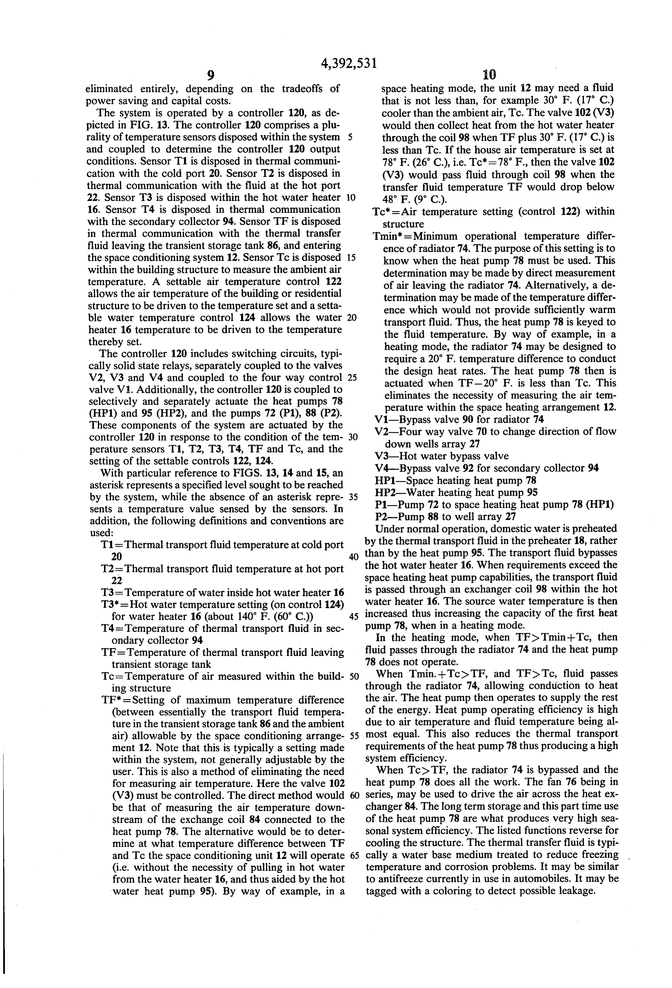
eliminated entirely, depending on the tradeoffs of space heating mode, the unit 12 may need a fluid power saving and capital costs. that is not less than, for example 30 F. (17. C.) The system is operated by a controller 120, as de cooler than the ambient air, Tc. The valve 102 (V3) picted in FIG. 13. The controller 120 comprises a plu would then collect heat from the hot water heater rality of temperature sensors disposed within the system through the coil 98 when TFplus 30' F. (17° C) is and coupled to determine the controller 120 output less than Tc. If the house air temperature is set at conditions. Sensor T1 is disposed in thermal communi 78 F. (26° C), i.e. Tc=78 F., then the valve 102 cation with the cold port 20. Sensor T2 is disposed in (V3) would pass fluid through coil 98 when the thermal communication with the fluid at the hot port transfer fluid temperature TF would drop below 22. Sensor T3 is disposed within the hot water heater O 48° F (9° C).
16. Sensor T4 is disposed in thermal communication Tc=Air temperature setting (control 122) within with the secondary collector 94. Sensor TF is disposed structure in thermal communication with the thermal transfer Tmin = Minimum operational temperature differ fluid leaving the transient storage tank 86, and entering ence of radiator 74. The purpose of this setting is to the space conditioning system 12. Sensor Tc is disposed 15 know when the heat pump 78 must be used. This within the building structure to measure the ambient air determination may be made by direct measurement temperature. A settable air temperature control 122 of air leaving the radiator 74. Alternatively, a de allows the air temperature of the building or residential termination may be made of the temperature differ structure to be driven to the temperature set and a setta ence which would not provide sufficiently warm ble water temperature control 124 allows the water 20 transport fluid. Thus, the heat pump 78 is keyed to heater 16 temperature to be driven to the temperature the fluid temperature. By way of example, in a thereby set. heating mode, the radiator 74 may be designed to The controller 120 includes switching circuits, typi require a 20 F. temperature difference to conduct cally solid state relays, separately coupled to the valves the design heat rates. The heat pump 78 then is V2, V3 and V4 and coupled to the four way control 25 actuated when TF-20 F. is less than Tc. This valve V1. Additionally, the controller 120 is coupled to eliminates the necessity of measuring the air tem selectively and separately actuate the heat pumps 78 perature within the space heating arrangement 12. (HP1) and 95 (HP2), and the pumps 72 (P1), 88 (P2). V1-Bypass valve 90 for radiator 74 These components of the system are actuated by the V2-Four way valve 70 to change direction of flow controller 120 in response to the condition of the tem 30 down wells array 27 perature sensors T1, T2, T3, T4, TF and Tc, and the V3-Hot water bypass valve setting of the settable controls 122, 124. V4-Bypass valve 92 for secondary collector 94 With particular reference to FIGS. 13, 14 and 15, an HP1-Space heating heat pump 78 asterisk represents a specified level sought to be reached by the system, while the absence of an asterisk repre 35 HP2-Water heating heat pump 95 P1-Pump 72 to space heating heat pump 78 (HP1) sents a temperature value sensed by the sensors. In P2-Pump 88 to well array 27 addition, the following definitions and conventions are Under normal operation, domestic water is preheated used:
T1=Thermal transport fluid temperature at cold port by the thermal transport fluid in the preheater 18, rather 20 than by the heat pump 95. The transport fluid bypasses T2=Thermal transport fluid temperature at hot port the hot water heater 16. When requirements exceed the space heating heat pump capabilities, the transport fluid
T3=Temperature of water inside hot water heater 16 is passed through an exchanger coil 98 within the hot T3*=Hot water temperature setting (on control 124) water heater 16. The source water temperature is then for water heater 16 (about 140 F. (60° C)) 45 increased thus increasing the capacity of the first heat T4=Temperature of thermal transport fluid in sec pump 78, when in a heating mode.
ondary collector 94 In the heating mode, when TF2Tmin-Tc, then TF=Temperature of thermal transport fluid leaving fluid passes through the radiator 74 and the heat pump transient storage tank 78 does not operate.
Tc=Temperature of air measured within the build 50 When Tmin.--TclTF, and TFeTc, fluid passes ing structure through the radiator 74, allowing conduction to heat TF* = Setting of maximum temperature difference the air. The heat pump then operates to supply the rest (between essentially the transport fluid tempera of the energy. Heat pump operating efficiency is high ture in the transient storage tank 86 and the ambient due to air temperature and fluid temperature being al air) allowable by the space conditioning arrange 55 most equal. This also reduces the thermal transport ment 12. Note that this is typically a setting made requirements of the heat pump 78thus producing a high within the system, not generally adjustable by the system efficiency.
user. This is also a method of eliminating the need When TclTF, the radiator 74 is bypassed and the for measuring air temperature. Here the valve 102 heat pump 78 does all the work. The fan 76 being in (V3) must be controlled. The direct method would series, may be used to drive the air across the heat ex be that of measuring the air temperature down changer 84. The long term storage and this part time use stream of the exchange coil 84 connected to the of the heat pump 78 are what produces very high sea heat pump 78. The alternative would be to deter sonal system efficiency. The listed functions reverse for mine at what temperature difference between TF cooling the structure. The thermal transfer fluid is typi and Tc the space conditioning unit 12 will operate 65 cally a water base medium treated to reduce freezing (i.e. without the necessity of pulling in hot water temperature and corrosion problems. It may be similar from the water heater 16, and thus aided by the hot to antifreeze currently in use in automobiles. It may be water heat pump 95). By way of example, in a tagged with a coloring to detect possible leakage.
Page 14
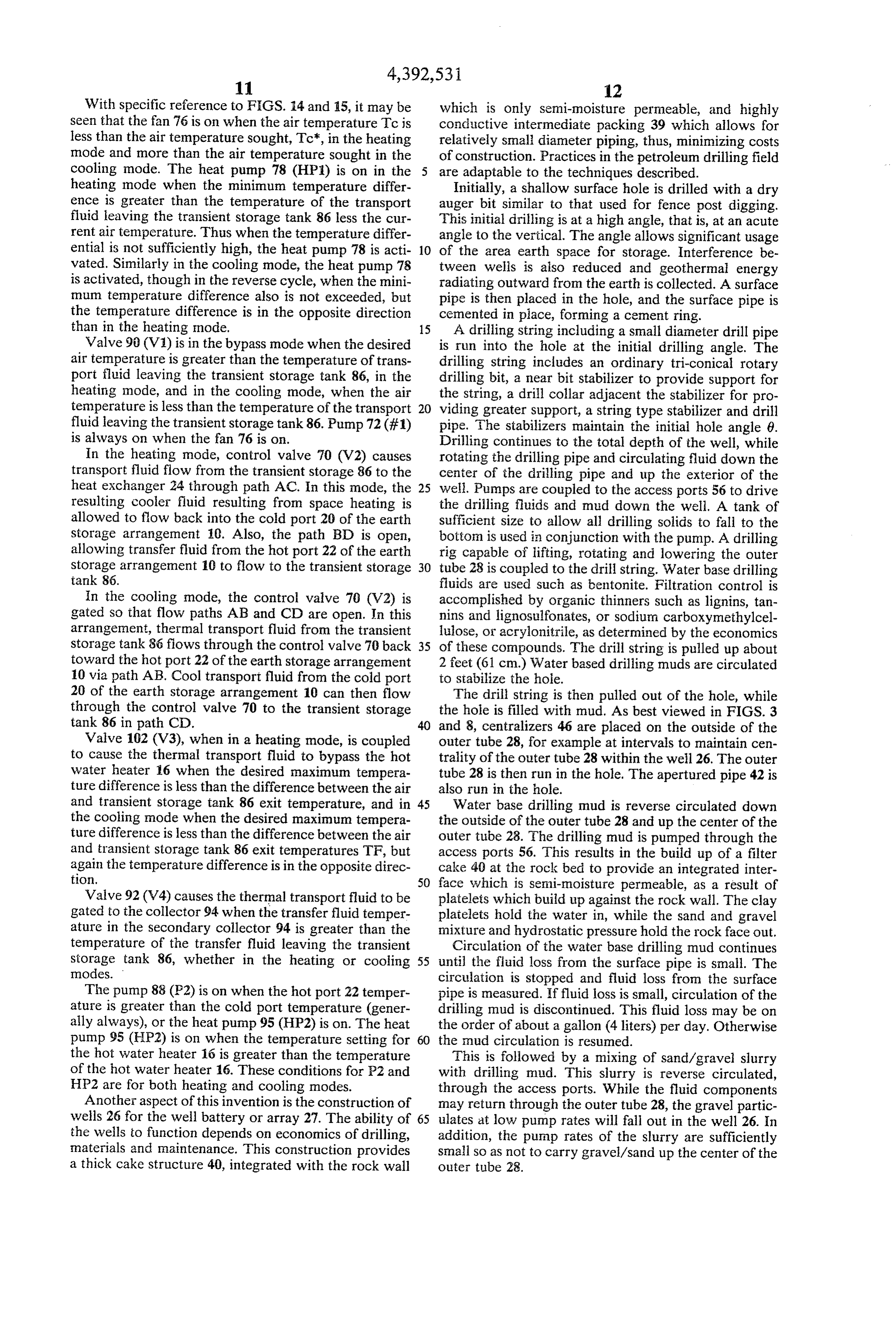
With specific reference to FIGS. 14 and 15, it may be which is only semi-moisture permeable, and highly seen that the fan 76 is on when the air temperature Tc is conductive intermediate packing 39 which allows for less than the air temperature sought, Tc, in the heating relatively small diameter piping, thus, minimizing costs mode and more than the air temperature sought in the of construction. Practices in the petroleum drilling field cooling mode. The heat pump 78 (HP) is on in the are adaptable to the techniques described.
heating mode when the minimum temperature differ Initially, a shallow surface hole is drilled with a dry ence is greater than the temperature of the transport auger bit similar to that used for fence post digging. fluid leaving the transient storage tank 86 less the cur This initial drilling is at a high angle, that is, at an acute rent air temperature. Thus when the temperature differ angle to the vertical. The angle allows significant usage ential is not sufficiently high, the heat pump 78 is acti 10 of the area earth space for storage. Interference be vated. Similarly in the cooling mode, the heat pump 78 tween wells is also reduced and geothermal energy is activated, though in the reverse cycle, when the mini radiating outward from the earth is collected. A surface mum temperature difference also is not exceeded, but pipe is then placed in the hole, and the surface pipe is the temperature difference is in the opposite direction cemented in place, forming a cement ring. than in the heating node. 15 A drilling string including a small diameter drill pipe Valve 90 (V1) is in the bypass mode when the desired is run into the hole at the initial drilling angle. The air temperature is greater than the temperature of trans drilling string includes an ordinary tri-conical rotary port fluid leaving the transient storage tank 86, in the drilling bit, a near bit stabilizer to provide support for heating mode, and in the cooling mode, when the air the string, a drill collar adjacent the stabilizer for pro temperature is less than the temperature of the transport 20 viding greater support, a string type stabilizer and drill fluid leaving the transient storage tank 86. Pump 72 (#1) pipe. The stabilizers maintain the initial hole angle 6. is always on when the fan 76 is on. Drilling continues to the total depth of the well, while In the heating mode, control valve 70 (V2) causes rotating the drilling pipe and circulating fluid down the transport fluid flow from the transient storage 86 to the center of the drilling pipe and up the exterior of the heat exchanger 24 through path AC. In this mode, the 25 well. Pumps are coupled to the access ports 56 to drive resulting cooler fluid resulting from space heating is the drilling fluids and mud down the well. A tank of allowed to flow back into the cold port 20 of the earth sufficient size to allow all drilling solids to fall to the storage arrangement 10. Also, the path BD is open, bottom is used in conjunction with the pump. A drilling allowing transfer fluid from the hot port 22 of the earth rig capable of lifting, rotating and lowering the outer storage arrangement 10 to flow to the transient storage 30 tube 28 is coupled to the drill string. Water base drilling tank 86. fluids are used such as bentonite. Filtration control is In the cooling mode, the control valve 70 (V2) is accomplished by organic thinners such as lignins, tan gated so that flow paths AB and CD are open. In this nins and lignosulfonates, or sodium carboxymethylcel arrangement, thermal transport fluid from the transient lulose, or acrylonitrile, as determined by the economics storage tank 86 fiows through the control valve 70 back 35 of these compounds. The drill string is pulled up about toward the hot port 22 of the earth storage arrangement 2 feet (61 cm.) Water based drilling muds are circulated 10 via path AB. Cool transport fluid from the cold port to stabilize the hole.
20 of the earth storage arrangement 10 can then flow The drill string is then pulled out of the hole, while through the control valve 70 to the transient storage the hole is filled with mud. As best viewed in FIGS. 3 tank 86 in path CD. and 8, centralizers 46 are placed on the outside of the Valve 102 (V3), when in a heating mode, is coupled outer tube 28, for example at intervals to maintain cen to cause the thermal transport fluid to bypass the hot trality of the outer tube 28 within the well 26. The outer water heater 16 when the desired maximum tempera tube 28 is then run in the hole. The apertured pipe 42 is ture difference is less than the difference between the air also run in the hole.
and transient storage tank 86 exit temperature, and in 45 Water base drilling mud is reverse circulated down the cooling mode when the desired maximum tempera the outside of the outer tube 28 and up the center of the ture difference is less than the difference between the air outer tube 28. The drilling mud is pumped through the and transient storage tank 86 exit temperatures TF, but access ports 56. This results in the build up of a filter again the temperature difference is in the opposite direc cake 40 at the rock bed to provide an integrated inter tion. 50 face which is semi-moisture permeable, as a result of Valve 92 (V4) causes the thermal transport fluid to be platelets which build up against the rock wall. The clay gated to the collector 94 when the transfer fluid temper platelets hold the water in, while the sand and gravel ature in the secondary collector 94 is greater than the mixture and hydrostatic pressure hold the rock face out. temperature of the transfer fluid leaving the transient Circulation of the water base drilling mud continues storage tank 86, whether in the heating or cooling 55 until the fluid loss from the surface pipe is small. The modes. circulation is stopped and fluid loss from the surface The pump 88 (P2) is on when the hot port 22 temper pipe is measured. If fluid loss is small, circulation of the ature is greater than the cold port temperature (gener drilling mud is discontinued. This fluid loss may be on ally always), or the heat pump 95 (HP2) is on. The heat the order of about a gallon (4 liters) per day. Otherwise pump 95 (HP2) is on when the temperature setting for 60 the mud circulation is resumed.
the hot water heater 16 is greater than the temperature This is followed by a mixing of sand/gravel slurry of the hot water heater 16. These conditions for P2 and with drilling mud. This slurry is reverse circulated, HP2 are for both heating and cooling modes. through the access ports. While the fluid components Another aspect of this invention is the construction of may return through the outer tube 28, the gravel partic wells 26 for the well battery or array 27. The ability of 65 ulates at low pump rates will fall out in the well 26. In the wells to function depends on economics of drilling, addition, the pump rates of the slurry are sufficiently materials and maintenance. This construction provides small so as not to carry gravel/sand up the center of the a thick cake structure 40, integrated with the rock wall outer tube 28.
Page 15
An alternative example for the process is useful 5. The invention as set forth in claim 4 and in which where high pressures are encountered in ports 56. A the tube comprises a one-way valve adjacent the lower second small diameter tube is lowered into the well 26 extremity of the first tube means. outside of the outer tube 28 to the top of the level of 6. The invention as set forth in claim 4 and in which sand/gravel in the well. The slurry is then pumped the means for maintaining high themal conductivity at down the well through the small diameter tube, but the fluid transport interface comprises an apertured now the fluid returns through the port 56. The new tube longitudinal pipe generally parallel to the first tube is pulled from the well as the level of the sand/gravel means, and means for supplying a liquid to the aper moves up the well. Following the packing of the outer 10 tured pipe.
tube the inner tube 34 is lowered inside of the outer tube 7. The invention as set forth in claim 3 or 6 and com 28 into the well. prising means for maintaining a constant liquid pressure While the invention has been particularly shown and on the particulate mass.
described with reference to preferred examples thereof, 8. The invention as set forth in claim 6 and compris it will be understood by those skilled in the art that ing means for maintaining constant liquid pressure on various changes in form and details may be made 15 the particulate mass and in which the constant pressure therein without departing from the spirit and scope of maintaining means are coupled to the apertured longitu the invention. dinal pipe.
What is claimed is: 9. The invention as set forth in claim 4 and in which 1. An earth coupled structural energy system com 20 the substantially moisture impervious transition com prising: prises bentonite.
an energy distribution system for selectively applying 10. The invention as set forth in claim 1 and compris thermal energy within a building structure; ing means for maintaining a constant liquid pressure earth storage means for communicating thermal en within a region defined by the earth interface surface ergy with the earth, the earth storage means having 25 area11.and the fluid transport means interface. a substantially moisture impervious integrated prising:An earth coupled structural energy system com earth interface, thereby maintaining substantial an energy distribution system for selectively supply thermal conductive moisture within the earth stor age means, yet providing conduction to the earth at ing thermal energy within a building structure; the integrated earth interface, the integrated earth 30 earth storage means for communicating thermal en interface generally defining an earth interface sur ergy with the earth, the earth storage means having face area; an integrated earth interface generally defining an fluid transport means disposed within the earth stor earth interface surface area, the earth storage age means for circulating a thermal transfer fluid means comprising an array of wells disposed within through the earth storage means; 35 the earth;
the fluid transport means having an interface with the fluid transport means disposed within the earth stor earth storage means, the fluid transport means in age means for circulating a thermal transfer fluid terface defining a surface surrounded in spaced through the earth storage means; apart relationship to the earth interface surface the fluid transport means comprises longitudinal first area;
tube means within each well, the first tube means means for maintaining a high thermal conductivity at defining an external surface at the fluid transport the fluid transport means interface; and means interface;
means for thermally communicating with the thermal the earth storage means comprising an intermediate particulate volumetric mass surrounding the tube transfer fluid to effect thermal changes in the en 45 and extending radially to the integrated earth inter ergy distribution system; face;
the earth storage means having a high thermal perme the fluid transport means having an interface with the ability, whereby thermal energy is readily con earth storage means, the fluid transport means in ducted between the earth and the fluid transport terface defining a surface of substantially smaller means with minimal thermal radiation. 50 area than the earth interface surface area; 2. The invention as set forth in claim 1 and in which means for maintaining a high thermal conductivity at the earth interface surface area is at least twice the area the fluid transport means interface; and of the fluid transport means interface. means for thermally communicating with the thermal 3. The invention as set forth in claim 1 and in which transfer fluid to effect thermal changes in the en the earth storage means comprises a well defining a well 55 ergy distribution system; depth; the earth storage means having a high thermal perme the fluid transport means comprises longitudinal first ability, whereby thermal energy is readily con tube means within the well, the first tube means ducted between the earth and the fluid transport defining an external surface at the fluid transport means with minimum thermal radiation. means interface and a first tube radius at the exter 60 12. The invention as set forth in claim 11 and in which nal surface; the integrated earth interface comprises a substantially the earth storage means comprising an intermediate moisture impervious clay platelet transition, thereby particulate volumetric mass surrounding the first maintaining substantial thermal conductive moisture tube means and extending radially to the integrated within the earth storage means, yet providing thermal earth interface. 65 conduction to the earth at the integrated interface. 4. The invention as set forth in claim 3 and in which 13. The invention as set forth in claim 12 and in which the integrated earth interface comprises a clay platelet the tube comprises a first flow path central to the tube transition. and a second flow path exterior to the first flow path,
Page 16
the first and second flow paths coupled serially to one means for maintaining moisture within the particulate another remote from the earth surface. mass at the fluid transport means interface. 14. The invention as set forth in claim 13 and in which 27. The invention as set forth in claim 26 and com the means providing the second flow path comprises an prising means coupled to the first conduit means adja inner tube means concentric with the first tube means. cent the interior region of the end to allow slurry fluid 15. The invention as set forth in claim 14 and in which to be pumped upwardly through the conduit during the the first tube means has a lower region and the inven placement of the sand/gravel mixture in the well during tion comprises a one way valve adjacent the lower well construction, yet preventing the escape of heat region of the first tube means. transfer fluid from the first conduit means, when in use. 16. The invention as set forth in claim 14 and in which O 28. The invention as set forth in claim 27 and in which the means for maintaining high thermal conductivity at the moisture maintaining means comprises third conduit the fluid transport interface comprises an apertured means external to the first conduit means, disposed longitudinal pipe generally parallel to the first tube longitudinally within the well.
means, and means for supplying a liquid to the aper 29. The invention as set forth in claim 28 and in tured pipe. 15 which:
17. The invention as set forth in claim 16 and com the third conduit means comprises a slotted pipe; and prising means for maintaining a constant liquid pressure the arrangement further comprises on the particulate mass. a plurality of spaced apart centralizers disposed in 18. The invention as set forth in claim 14 and in which spaced apart relationship along the first conduit the fluid transport means comprises a first port and a 20 means, the first conduit means defining a circum second port, each tube means within each well being ference, each centralizer comprising a pair of coupled in series, the first port being coupled to the first spaced apart annular hubs engaging the circumfer flow path of one tube and the second port being coupled ence of the first conduit means, and a plurality of to the second flow path of the other tube, whereby the 25 convex spokes extending between each hub pair to entire array may provide an enhanced length flow path. thereby maintain the first conduit means generally 19. The invention as set forth in claim 18 and in which centrally within the well during construction. the array comprises a line source array. 30. The invention as set forth in claim 29 and com 20. The invention as set forth in claim 18 and in which prising:
the array comprises a centered point source. a shallow pipe within the well adjacent the earth 21. The invention as set forth in claim 18 and in which 30 surface and a cement ring surrounding the shallow the array comprises an uncentered point source. pipe;
22. The invention as set forth in claims 18, 19, 20 or 21 means disposed adjacent the shallow pipe for porting and comprising means for circulating fluid in the fluid a slurry to and from the well during well construc transport means array in a first direction and in a second 35 tion;
direction, in response to demands for fluids of higher inlet and outlet means for porting a thermal transfer and lower temperatures. fluid through the first and second conduit means; 23. The invention as set forth in claim 12, 13, 14, 15, and 16, 18, 19, 20 or 21 and in which the integrated earth the means coupled to the first conduit means com interface comprises bentonite clays. 40 prises a check valve.
24. The invention as set forth in claim 12, 13, 14, 15, 31. The invention as set forth in claim 26, 27, 28, 29 or 16, 18, 19, 20 or 21 and in which the integrated earth 30 and in which the well diameter is greater than twice interface comprises clay and a thinner selected from the the diameter of the first conduit means. group consisting of lignites, tannins and lignosulfonates. 32. The invention as set forth in claim 26, 27, 28, 29 or 25. The invention as set forth in claim 12, 13, 14, 15, 45 30 and in which the integrated earth interface has an 16, 18, 19, 20 or 21 and in which the integrated earth inner diameter greater than twice the diameter of the interface comprises clay and polymers selected from the first conduit means and the integrated earth interface group consisting acrylic polymers and sodium carboxy comprises bentonite.
methylcellulose. 33. The invention as set forth in claim 26, 27, 28, 29 or 26. An earth coupled thermal storage arrangement 50 30 and in which the integrated earth interface has a comprising: diameter greater than twice the diameter of the first a generally longitudinal well defining a well depth conduit means and the integrated earth interface com and having a substantially moisture impervious prises a bentonite clay and a thinner selected from the integrated earth interface generally defining an group consisting of lignites, tannins and lignosulfonates. earth interface surface area; 55 34. The process for constructing a thermal storage fluid transport means for communicating thermal well, comprising the steps of:
energy with the earth, comprising first conduit drilling a shallow surface hole with a dry auger bit at means for circulating a thermal transport fluid and an angle to the vertical;
thermally communicating with the earth, the first placing surface pipe in the hole;
conduit means disposed within the substantial cementing the surface string to the surface; depth of the well and having an end defining an running in hole a drilling string;
interior region, and second conduit means for cir drilling to a well depth, while rotating pipe and circu culating thermal transport fluid to and from the lating fluid down the center of the pipe and up the first conduit means, the second conduit means dis exterior;
posed within the first conduit means; 65 pulling up from the hole a short distance to allow the the first conduit means surrounded by an intermedi circulation of mud;
ate volumetric particulate mass comprising a circulating water base drilling mud to stabilize the sand/gravel mixture; and hole;
Page 17
pulling out of the hole the drilling string, while filling ate particulate mass extending adjacent to the filter the hole with mud; cake.
running in hole an outer tube with centralizers; 36. The process as set forth in claim 35 and in which the thermal transfer conduit has an outer circumference running in hole a slotted pipe; 5 less than one-half the circumference of the filter cake. circulating down outside of the outer tube and up 37. The process as set forth in claim 36 and compris center a water base drilling mud; ing the steps of:
stopping the circulation and measuring the fluid loss drilling an initial shallow hole at an angle; from the surface pipe and continuing until fluid loss cementing a surface pipe in the shallow hole. is small; 10 38. The process as set forth in claim 36 and compris mixing gravel and sand slurry with a drilling mud; ing the steps of:
and running a conduit of smaller diameter than the ther mal transfer conduit, in the hole beside the thermal reverse circulating the slurry down the well to pack transfer conduit; and the space between the outer tube and the rock face, 15 pulling out the smaller conduit as the sand/gravel at a slow rate. slurry moves up the well.
35. The process for constructing a thermal storage 39. The invention as set forth in claim 38 and com well comprising the steps of: prising the steps of:
drilling a well; running a drill string within the hole, while circulat circulating mud through the hole to establish a filter 20 ing mud; and cake; measuring moisture loss from the well; and running a thermal transfer conduit in the hole; continuing to circulate drilling mud until moisture running a drill string within the hole while circulating loss is at least less than a predetermined rate. 40. The invention as set forth in claim 39 and com mud; 25 prising the steps of:
measuring moisture loss from the well; and drilling an initial shallow hole at an angle; and reverse circulating a sand/gravel slurry through the cementing a surfacek pipe is k in the shallow hole.
thermal transfer conduit to establish an intermedi
Provenance
- Collection
- Cited prior art
- Original PDF
- patentimages.storage.googleapis.com →
- Filed
- 1981-10-09
- Pages
- 17
- Method
- pdftotext (the PDF's own text layer) + pdftoppm 300dpi page scans
- Source
- Google Patents bibliographic record
- Granted
- 1983-07-12
- Inventors
- Joe J. Ippolito
- Transcribed from
- patentimages.storage.googleapis.com →