patent · US20120132393A1
Arrangement and method for storing thermal energy
31 May 2012
Page 1 — bibliographic record
(19) United States (12) Patent Application Publication (10) Pub. No.: US 2012/0132393 A1
Pilebro et al. (43) Pub. Date: May 31, 2012 (54) ARRANGEMENT AND METHOD FOR Publication Classification
STORING THERMAL ENERGY
(75) Inventors: Hans Pilebro, Enebyberg (SE): F24, 3/08 (2006.01) Hakan Eg Andersson, Taby (SE) B23P6/00 (2006.01)
(73) Assignee: SKANSKA SVERIGE AB, Solna (52) U.S. Cl. ........................................ 165/45; 29/402.01 (SE) (57) ABSTRACT (21) Appl. No.: 13/388,648 An arrangement for storing thermal energy, having at least (22) PCT Filed: Jul. 12, 2010 one subterranean chamber for holding a first fluid, wherein a passage holding a second fluid is extended outside at least a (86). PCT No.: PCT/SE2O10/050808 part of the at last one chamber. The at least one channel is arranged to allow fluid communication of the first fluid
S371 (c)(1), between different sections of the chamber, and/or in that at (2), (4) Date: Feb. 2, 2012 least one channel is arranged to allow fluid communication of the second fluid between different sections of the passage. A (30) Foreign Application Priority Data method is also disclosed for improving an arrangement for storing thermal energy having the steps of providing at least
Aug. 3, 2009 (SE) .................................... O950576-9 one channel within the arrangement.
Page 2
Patent Application Publication May 31, 2012 Sheet 1 of 8 US 2012/0132393 A1
rts 'm w 'a ris. 'was's...w, w, ... e., i.e.: ye de see SE 's so six '-s's 's 's 'Se's s. ss is trix ers ex: xer. was re. --- so axxaanxraxxaaaaaaaaaaaaaasesses
Page 3
Drawing sheet — no readable text.
Page 4
Drawing sheet — no readable text.
Page 5
Drawing sheet — no readable text.
Page 6
Drawing sheet — no readable text.
Page 7
Drawing sheet — no readable text.
Page 8
Drawing sheet — no readable text.
Page 9
Drawing sheet — no readable text.
Page 10
US 2012/0132393 A1 May 31, 2012
ARRANGEMENT AND METHOD FOR Another purpose was to equalize the ground water pressure STORING THERMAL ENERGY around the cavern. A ground water flow would then enter into the tunnel “upstream” and leak out "downstream from the
TECHNICAL FIELD tunnel. No further attempts were performed to minimize heat leakage due to ground water flow, if any.
0001. The invention relates in general to an arrangement 0010. It therefore exist a need to provide an improved for storing thermal energy. In particular the invention relates arrangement for storing thermal energy underground. to an arrangement for storing thermal energy of a fluid pro vided in a container, such as an underground rock cavity. SUMMARY OF THE INVENTION 0002 The invention also relates to a method for improving an arrangement for storing thermal energy. 0011. An object according to an aspect of present inven tion is to provide an environment friendly arrangement for
BACKGROUND OF THE INVENTION storing thermal energy underground.
0012. An object according to an aspect of present inven 0003. Within various fields of application regarding mod tion is to provide an arrangement for storing thermal energy, ern energy technologies efficient possibilities for storage of in which arrangement overall thermal energy losses can be thermal energy is required. reduced.
0004 One technique of storing thermal energy is achieved 0013 Another object according to an aspect of the present by providing a fluid, such as e.g. water, in a Subterranean invention is to provide an improved arrangement for storing chamber. The thermal energy of the fluid is to a great extent thermal energy.
conserved within the chamber during an extended period of 0014. Yet another object of the invention is to provide a time. Today this technique is used in different parts of the more cost effective arrangement for storing thermal energy world so as to satisfy needs of storing thermal energy between requiring no or minimized maintenance. different seasons. 0015 These and other objects are achieved by an arrange 0005 Storage of thermal energy in caverns is mainly ment for storing internal energy according to claim 1. achieved by a temperature difference within water filled in an 0016. According to an aspect of the invention there is excavated cavern. As water has approximately double heat provided an arrangement for storing thermal energy. The capacity compared to a corresponding Volume of rock, effi arrangement comprises at least one subterranean chamber for cient heat storage is achieved according to this method. The holding a first fluid, wherein a passage holding a second fluid rock surrounding the cavernis used as insulation. Due to large is extended outside at least a part of said at last one chamber, scale effects a relatively good insulation is achieved. The wherein the at least one channel is arranged to allow fluid Surrounding rock also to Some extent contributes to the stor communication of said first fluid between different sections age function. of said chamber, and/or the at least one channel is arranged to 0006 Due to high initial costs relating to preparation of allow fluid communication of said second fluid between dif caverns for storing thermal energy, few projects have been ferent sections of said passage.
realized so far. One thermal energy storing plant is located in 0017. By providing at least one channel allowing fluid Lyckebo, Sweden. The plant for thermal energy storage in communication of said first fluid between separated sections Lyckebo basically comprises a tunnel Surrounding and an of the chamber an improved thermal storage capacity is excavated cavern having storage volume of about 100.000 achieved.
m3. Both the tunnel and the chamber are filled with water. The 0018. By providing at least one channel allowing fluid tunnel and the chamber define separated volumes for holding communication of said second fluid between separated sec water for storage of thermal energy. The water contained in tions of the passage an improved thermal storage capacity is the tunnel and the chamber, respectively, are substantially in achieved.
fluid communication with each other. However, as depicted 0019. The media, such as e.g. rock or soil, surrounding the below, the plant suffers from some drawbacks. chamber and the at least one channel associated thereto hold 0007. This particular plant has been in use since 1984 and ing the first fluid is advantageously providing a first energy is today still in operation. In the Lyckebo plant telescopic Storage.
extraction pipes have been used. The telescopic extraction 0020. The media, such as e.g. rock or soil, surrounding the pipes are arranged to extract water at level in the cavern passage and the at least one channel associated thereto hold having a desired temperature and to return used water having ing the first fluidisadvantageously providing a second energy another temperature at an appropriate level in the cavern. The storage. The second energy storage is advantageously pro warmest water in the storage may be spared until required. vided outside the first energy storage. Use of the telescopic extraction and return pipes allows a 0021. The first and second energy storage advantageously distinct separation layer between warmer and colder water provides an increased thermal storage capacity of the inven within the cavern to during use continuously be reduced to a tive arrangement.
minimum. 0022. By providing the at least one channel allowing fluid 0008. In the Lyckebo plant some unexpected leakage of communication of said first fluid and at least one channel water from the storage cavern to the Surrounding access tun allowing fluid communication of said second fluid a further nel has been detected. Said leakage has resulted in an improved arrangement for storing thermal energy is achieved increased heat loss from the stored water by approximately according to the invention.
30%. The surrounding tunnel achieved a higher temperature 0023 The first fluid is containing a certain thermal energy. than expected. Thermal energy stored in the tunnel has not The thermal energy of the first fluid may be substantially been efficiently utilized in the plant. conserved within the chamber during an extended period of 0009. The “surrounding access tunnel’ in Lyckebo was time. The thermal energy of the first fluid may be increased initially designed to minimize required area for the storage. during a Summer period by means of e.g. Solar panels and
Page 11
US 2012/0132393 A1 May 31, 2012
stored in the chamber for later use. The thermal energy of the 0034. According to one example the at least one channel is first fluid may be used during a winter period. a drilled hole formed by means of a drilling machine. Accord 0024. Alternatively, the thermal energy of the first fluid ing one example the channel is formed by jacking. may be reduced during a winter period and stored in the 0035. The dimension of the at least one channel may be chamber for later use. The thermal energy of the first fluid Suitable chosen. According to one example the channel is a may be used during a Summer period. drilled hole having a diameter of 1 decimetre. According to a 0025. In a similar way, the second fluid is containing a second example the channel is a drilled hole having a diam certain thermal energy. The thermal energy of the second fluid eter of 2 decimetres. According to a second example the may be substantially conserved within the passage during an channel is a drilled hole having a diameter of 3 decimetres. extended period of time. The thermal energy of the second According to an embodiment of the invention the at least one fluid may be increased during a Summer period by means of channel has an arbitrary dimension. e.g. Solar panels and stored in the passage for later use. The 0036 By providing a plurality of channels between differ thermal energy of the second fluid may be used during a ent sections of the passage an effective fluid curtain is winter period. achieved. According to one example 10-100 channels 0026. Alternatively, the thermal energy of the second fluid arranged to hold the second fluid are provided. According to may be reduced during a winter period and stored in the one example 10-100 channels arranged to hold the first fluid passage for later use. The thermal energy of the second fluid are provided. According to one example more than 100 chan may be used during a Summer period. nels arranged to hold the first fluid are provided. According to 0027. The sections of the passage may be separated in one example more than 100 channels arranged to hold the height. In a case where the sections of the passage are sepa second fluid are provided.
rated in height a more efficient gradient thermal flow of the 0037. The channels are arranged to hold a part of the second fluid within the arrangement is achieved. second fluid. The at least one chamber holding the first fluid 0028. The sections of the chamber may be separated in and the at least one channel holding the second fluid is Sub height. In a case where the sections of the chamber are sepa stantially not in fluid communication with each other. How rated in height a more efficient gradient thermal flow of the ever, a small extent of the first fluid may escape from the first fluid within the arrangement is achieved. chamber due to e.g. inherent characteristics of a Surrounding 0029. The sections of the passage interconnecting the at medium, Such as e.g. rock. The passage and the thereto con least one channel may be separated in height. The sections of necting channels are arranged to receive some of the escaped the chamber interconnecting the at least one channel may be first fluid and is thereby providing a more environmental separated in height. friendly arrangement for storing thermal energy. 0030 The passage may be surrounding said at last one 0038. In a case where the first fluid is oil, saltwater, ammo chamber. The passage may be a tunnel used when forming the nia or other fluid other than substantially pure water, the Subterranean chamber. In case the passage is Surrounding the second fluid has to be of higher pressure than the first fluid at least one chamber an increased thermal storage capacity is resulting in leakage into the chamber. achieved. Thermal interaction between the material Sur rounding the chamber and the passage is providing an overall 0039. The at least one channel may be vertically arranged improved arrangement for storing thermal energy, according between said separated sections of the passage. By providing to an aspect of the invention. the at least one channel Vertically, a maximum thermal gra dient flow is achieved.
0031. By using the passage, required for forming the at least one chamber for storing said second fluid, an improved 0040. The at least one channel may be vertically arranged arrangement for storing thermal energy is achieved. The pas between said separated sections of the chamber. By providing sage is arranged to hold the second fluid. The chamber hold the at least one channel Vertically, a maximum thermal gra dient flow is achieved.
ing the first fluid and the passage holding the second fluid is
Substantially not in fluid communication with each other. 0041. The at least one channel may be arranged between However, a small extent of the first fluid may escape from the said separated sections of said passage at an arbitrary incli chamber due to e.g. inherent characteristics of a Surrounding nation relative a horizontal plane allowing thermal natural medium, Such as e.g. a rock. The passage is arranged to convection, Such as an inclination between 1:10 and vertical receive some of the escaped first fluid and is thereby provid relative the horizontal plane. By providing the at least one ing a larger energy storage capacity, as escaping energy can channel at an inclination between 1:10 and vertical relative be used in the second fluid. the horizontal plane, an increased energy storage capacity is 0032. The chamber holding the first fluid and the at least achieved.
one channel holding the second fluid is Substantially not in 0042. According to one embodiment the at least one chan fluid communication with each other. However, a small extent nel may be arranged between said separated sections of said of the first fluid may escape from the chamber due to e.g. passage at an inclination between horizontal and 1:10 relative inherent characteristics of the Surrounding medium. The at a horizontal plane. According to this embodiment thermal least one channel is arranged to receive some of the escaped natural convection of the second fluid is limited and a fluid first fluid and is thereby providing a larger energy storage pump and separation arrangements of the passage may be capacity. Suitable arranged within the inventive arrangement so as to 0033. The at least one channel may be a plurality of chan provide a desired flow of the second fluid within the arrange nels forming a fluid curtain outside said at least one chamber. ment.
The fluid curtain may comprise an arbitrary number of chan 0043. The passage 110 may comprise at least two sepa nels. The fluid curtain may comprise a suitable number of rated parts divided by a sealing element. The passage 110 channels. According to one example the fluid curtain com having at least two separated parts is herein referred to as a prises 10-100 channels. (one) passage 110.
Page 12
US 2012/0132393 A1 May 31, 2012
0044) The passage 110 may comprise two or more sepa generation and heating, biofuel heater, oilfired boiler, or a rated tunnels (passage 110). According to an aspect of the boiler powered by fossil fuel or biofuel, such as pellet. invention the at least one channel is provided between differ 0055 Alternatively a lake can be used as an energy source, ent sections of the separated tunnels. According to one allowing reducing thermal energy of the first and/or second example a chamber for storing the first fluid is at least partly fluid. Alternatively ambient air can be used as an energy Surrounded by two separated tunnels having at least one chan Source, allowing reducing thermal energy of the first and/or nel allowing fluid communication of the second fluid between second fluid. Alternatively roads or Streets can be used as an the two tunnels.
energy source, allowing reducing thermal energy of the first 0045. The first and/or second fluid may be chosen from a and/or second fluid. Alternatively airport runways can be group comprising: water, a mixture of water and a coolant, used as an energy source, allowing reducing thermal energy any liquid fuels, such as hydro carbons of fossil origin or of the first and/or second fluid. Alternatively roofs and outer biological origin (biofuel), Salt Solution, ammonia or other or inner walls of buildings can be used as an energy source, refrigerants.
0046 According to a preferred application the first fluid is allowing reducing thermal energy of the first and/or second water Substantially free from contamination. According to a fluid. Alternatively parking lots can be used as an energy preferred application the second fluid is water substantially Source, allowing reducing thermal energy of the first and/or second fluid.
free from contamination. Water is a many different geo graphic areas a cheap and environmental friendly fluid. 0056. According to one example lake can be used as an 0047. The chamber may be a cavern made in a rock. In a energy source, allowing increasing thermal energy of the first case where the chamber is a cavern in bedrock there is pro and/or second fluid. Alternatively ambient air can be used as vided a robust insulation for conserving thermal energy of the an energy source, allowing increasing thermal energy of the first fluid. This also holds true in a case where the passage is first and/or second fluid. Alternatively roads or streets can be formed in bedrock. used as an energy source, allowing increasing thermal energy 0048. The passage may be configured as a helix. The pas of the first and/or second fluid. Alternatively airport runways sage may be configured in a spiral form. The passage may can be used as an energy source, allowing increasing thermal have any shape so that it is at least partly surrounding the energy of the first and/or second fluid. Alternatively roofs and chamber. The passage may be configured in a Substantially outer or inner walls of buildings can be used as an energy helix formed shape. The helix shape is a desired shape in Source, allowing increasing thermal energy of the first and/or various applications because it provides an easy manufactur second fluid. Alternatively parking lots can be used as an ing process involving great access of heavy vehicles for energy source, allowing increasing thermal energy of the first removing material from both the passage itself and the cham and/or second fluid.
ber. According to one example the passage has a maximum 0057 According to an aspect of the invention a tempera inclination of dimensions 1:7.
0049. The arrangement may further comprise a first fluid ture of said first fluid is within a temperature interval of 4-100 communication means arranged to extract an arbitrarily por degrees Celsius. According to an aspect of the invention a tion of said first fluid from the chamber at a suitable vertical temperature of said first fluid is within an interval of 4-100 level so as to allow processing of said first fluid by means of degrees Celsius.
a first heat exchanger, wherein said first fluid communication 0058. In a case where the first fluid is water a suitable means further is arranged to return the processed first fluid to temperature interval may be -5-20 degrees Celsius. Accord the chamber at a suitable vertical level. ing to yet an example a suitable temperature interval may be 0050. A suitable level for extracting the arbitrary portion 0-4 degrees Celsius. According to yet an example a suitable of said first fluid may be an arbitrary vertical level of the temperature interval may be 4-15 degrees Celsius. passage. In practice it is desired to provide the first heat 0059. According to an aspect of the invention a tempera exchanger with a fluid having a predetermined temperature. It ture of said first fluid, being a refrigerant or other coolants, or may in different ways be possible to determine a temperature propane, is within a temperature interval of -50 to 20 degrees distribution within the first fluid and determine a suitable Celsius.
Vertical level of extraction accordingly. 0060 According to an aspect of the invention a tempera 0051. A suitable level for returning the processed first fluid ture of said first fluid is within a temperature interval of may beat a vertical level of the chamber holding the first fluid 90-200 degrees Celsius.
of about the same temperature as the processed first fluid. 0061 According to an aspect of the invention the arrange 0052. The arrangement may further comprise an energy ment may comprise two or three chambers, wherein the pas Source coupled to said first heat exchanger and/or a second sage holding the second fluid is extended outside at least a heat exchanger, which second heat exchanger is arranged to part of at last one chamber. The chambers may be arranged increase and/or reduce thermal energy of the first fluid and/or beside each other at a suitable distance from each other. the second fluid. According to one example two chambers are arranged beside 0053 According to what is depicted above the first fluid each other and a third chamber is arranged beneath said two may be used for heating purposes. The first fluid may alter chambers.
natively be used for cooling purposes. 0062 An arbitrary number of chambers may be provided 0054 The energy source may be any of a group of energy for storing thermal energy according to the invention. The two Sources comprising: a thermal electrical power arrangement or more chambers may contain mutually different kind of for heating and/or cogeneration of electricity and heat, a spare fluids. For example, a first chamber may contain and store unit, such as e.g. an emergency electricity generator, Solar water and a second chamber may contain a salt Solution or panels for heating or Solar panels for combined electrical combustible oil.
Page 13
US 2012/0132393 A1 May 31, 2012
0063. In certain configurations of the arrangement having 0074 The arrangement as such is environmental friendly two or more chambers containing different kind offirst fluids, due to fact that waste heat from in theory any energy source a separation member may be provided so as to separate each may made use of. Therefore an overall waste energy is chamber from each other. reduced.
0064. According to an aspect of the invention there is 0075. The arrangement requires low maintenance in the provided an arrangement wherein said at least one chamber long run due to that mechanical or electrical Support means may be a first chamber and a second chamber separated from may be kept up from the Surface of the ground. The mechani each other and vertically arranged relative each other, and cal and electrical Support means may for example be the first wherein at least one of said first and second chamber is and second heat exchanger. The mechanical and electrical Surrounded by the passage holding the second fluid. Support means may for example be the first and second fluid 0065 According to an aspect of the invention there is communication means. A low maintenance arrangement for provided an arrangement wherein said at least one chamber storing thermal energy is relatively cheap to operate. The may be a first chamber, a second chamber and a third chamber arrangement according to the invention is thus providing a separated from each other and vertically arranged relative cost effective solution to the problems stated above. each other, and wherein at least one of said first, second and 0076 Alternatively machine rooms comprising one or third chamber is Surrounded by the passage holding the sec more pumps for extracting and returning the first and/or the ond fluid. second fluid to the chamber and passage, respectively, may be 0066. The arrangement may further comprise a second provided in machine rooms underground. One or more heat fluid communication means arranged to extract an arbitrarily exchanger for operation according to an aspect of the inven portion of said second fluid from the passage at a Suitable tion may also be provided in the machine rooms under level so as to allow processing of said second fluid by means ground.
of a second heat exchanger, wherein said second fluid com 0077. By providing second fluid communication means munication means further is arranged to return the processed working in parallel with the first communication means second fluid to the passage at a Suitable vertical level. allowing to reduce or increase the thermal energy of the 0067. A suitable level for extracting the arbitrary portion second and first fluid, respectively, provides an arrangement of said second fluid may be an arbitrary vertical level of the for storing thermal energy having improved capacity relative passage. In practice it is desired to provide the second heat prior art arrangements.
exchanger with a fluid having a predetermined temperature. It 0078. A beneficial contribution of the invention is that may in different ways be possible to determine a temperature vertical arrangement of two or more chambers having a single distribution within the second fluid and determine a suitable passage allows use of a building site of minimized propor Vertical level of extraction accordingly. tions. Since land may be quite costly a minimal area on 0068 A suitable level for returning the processed second ground needs to be purchased before commencing construc fluid may be at a vertical level of the passage holding the tional work of the arrangement, such as blasting the passage and the chambers.
second fluid of about the same temperature as the processed 0079 Additional objects, advantages and novel features of second fluid.
0069. According to an aspect of the invention there is the present invention will become apparent to those skilled in provided a method for improving an arrangement for storing the art from the following details, as well as by practice of the thermal energy, wherein said arrangement comprises at least invention. While the invention is described below, it should be one subterranean chamber for holding a first fluid, wherein a understood that the invention is not limited to the specific passage holding a second fluid is extended outside at least a details disclosed. A person skilled in the art having access to the teachings herein will recognise additional applications, part of said at least one chamber. The method may comprise modifications and embodiments in other fields, which are the step of providing at least one channel to allow fluid com within the scope of the invention. munication of said first fluid between different sections of said chamber. The method may additionally, or alternatively, BRIEF DESCRIPTION OF THE DRAWINGS comprise the step of providing at least one channel to allow fluid communication of said second fluid between different 0080 For a more complete understanding of the present sections of the passage. invention and further objects and advantages thereof, refer 0070 The step of providing at least one channel may com ence is now made to the examples shown in the accompany prise the step of drilling said channel by means of a drilling ing drawings, wherein same reference numerals relate to Sub unit Such as e.g. a rock drilling machine. stantially the same features throughout the different 0071. The step of providing at least one channel may com drawings, in which drawings:
prise the step of applying a pipe constituting said channel by I0081 FIG. 1 schematically illustrates an arrangement for means of pipe jacking. storing thermal energy, according to an aspect of the inven 0072. One positive outcome of the arrangement according tion;
to an aspect of the invention is that a more reliable arrange I0082 FIG. 2 schematically illustrates an arrangement for ment for storing thermal energy is achieved. In case the cham storing thermal energy, according to an aspect of the inven ber is a cavern within a bed rock the arrangement is providing tion;
a relative disruption free environment. Rock or bed rock is I0083 FIG. 3 schematically illustrates an arrangement for considered to be a stable environment for storing thermal storing thermal energy, according to an aspect of the inven energy contained in a fluid Such as water. tion;
0073. Another positive outcome of the arrangement is that I0084 FIG. 4a-d schematically illustrates different chambers may be manufactured by TBM's. Further the pas arrangements for storing thermal energy, according to various sage and channels may be formed by pipe jacking. aspects of the invention;
Page 14
US 2012/0132393 A1 May 31, 2012
I0085 FIG. 5 schematically illustrates a side view of an passage 110 is substantially in balance with the pressure of arrangement for storing thermal energy, according to an the Surrounding ground water.
aspect of the invention; and (0094. A first shaft 150 is arranged from the surface 199 of I0086 FIG. 6 schematically illustrates a flow chart depict the ground to the chamber 105. The first shaft 150 may have ing a method for improving an arrangement for storing ther any suitable dimensions. There is provided a first fluid com mal energy, according to an aspect of the invention. munication device 155 arranged to extract a portion of a first fluid 106 from the chamber 105 at a Suitable vertical level and
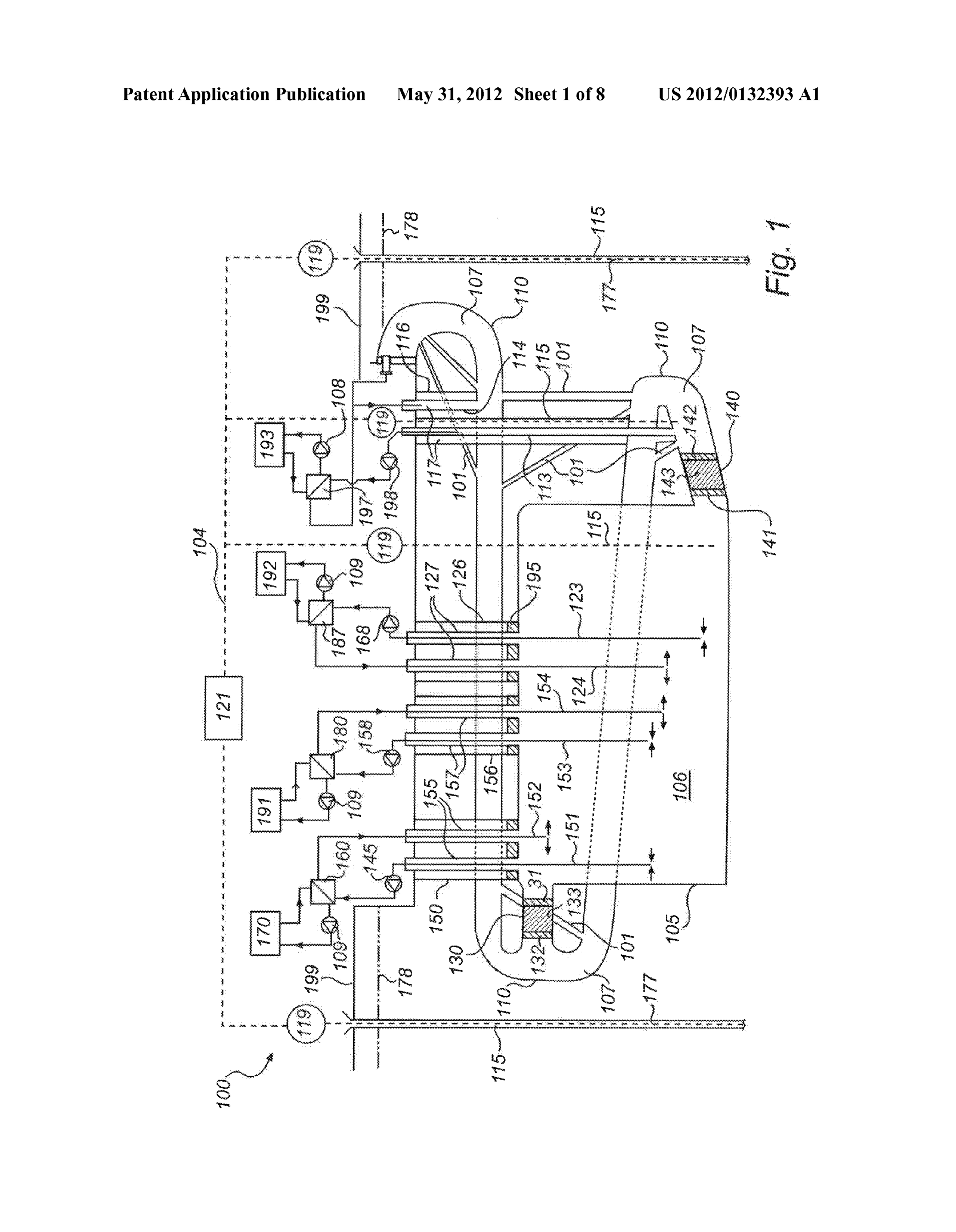
DETAILED DESCRIPTION OF THE DRAWINGS to provide the extracted portion of the first fluid 106 to a first I0087. With reference to FIG. 1 there is schematically illus heat exchanger 160. The first fluid communication device 155 trated an arrangement 100 for storing thermal energy, accord is also arranged to return the first fluid 106 back to the cham ing to an aspect of the invention. ber 105. The first fluid communication device 155 may com 0088 According to this example a passage 110 is provided prise a pump 145 being arranged to pump the first fluid 106 underground. A ground Surface is generally indicated by a from the chamber 105 to the first heat exchanger 160. The first reference numeral 199. The passage 110 has been formed by heat exchanger 160 is arranged to perform a heat transfer any Suitable means, such as drilling machines and/or explo process. The first fluid communication device 155 is arranged sives. Typically the passage 110 has a cross sectional area of to return the processed first fluid 106 back to the chamber 105 about 30-40 m2. According to this example the dimensions of at a suitable vertical level. The first communication means the passage 110 are about 6x6 meters. The passage 110 may 155 is generally designed to increase the thermal energy of also be referred to as a tunnel. Initially the purpose of forming the first fluid 106 by means of said heat transfer process. the passage 110 is to allow working crew to form a chamber 0.095 According to one example the first fluid communi 105. The chamber 105 is also referred to as a container or fluid cation device 155 comprises a pair of telescopic pipes, which storing means. The chamber 105 may have one or more initial may be controlled mutually independent. A first pipe 151 of inlets. The chamber 105 illustrated with reference to FIG. 1 the first fluid communication device 155 is arranged to extract has a first initial inlet 130 and a second initial inlet 140. the first fluid 106 from the chamber 105 at an arbitrary vertical I0089. The first initial inlet 130 is used when forming a roof level in the chamber 105. A second pipe 152 of the first fluid of the chamber 105. The roof and the walls of the chamber communication device 155 is arranged to return the first fluid 105 may be suitably enforced and/or sealed so as to improve 106 at an arbitrary vertical level in the chamber 105. robustness of the chamber 105 and to minimize leakage of (0096. A temperature distribution of the first fluid 106, seen e.g. ground water into the chamber 105. The second initial in a vertical perspective, is uneven. According to this example inlet 140 is used when forming a bottom part of the chamber the first fluid 106 has a temperature within a temperature 105. The Surrounding medium can be sealed by grouting so as range TA. The temperature range TA is ranging between 4 to avoid undesired leakage caused by inherent characteristics, degrees Celsius and 90 degrees Celsius. Due to inherent char Such as cracks, of the Surrounding medium. acteristics of water, colder water is located in a lower section 0090. After the chamber 105 has been prepared the first of the chamber 105, and the warmest water is located in an initial inlet 130 is sealed by at least one first concrete block uppermost section of the chamber 105. 131 and preferably a thereto spaced second concrete block (0097. A plurality of channels 101 are provided in the 132. The chamber 105 and the passage 110 are thermally arrangement 100 according to the invention. The channels sealed by means of a separation member. The chamber 105 101 may be drilled by means of a drilling machine. A second and the passage 110 are fluidly sealed by means of a separa fluid 107 is stored in the passage 110. tion member. Between the first concrete block 131 and the second concrete block 132 there is provided an insulation unit 0098. An energy source 170 is connected to the first heat 133 made of any suitable material. Such as gravel, Soil or a exchanger 160. The energy source 170 may be an arbitrary mixture of insulation and concrete or granulate concrete. Suitable energy source. According to a preferred embodiment Thereby there is provided a first open space within the cham waste heat of any existing energy source is used for increasing ber 105 and a second open space within the passage 110. thermal energy of the first fluid 106 within the arrangement 0091. After the chamber 105 has been prepared the second 100 for storing thermal energy. Waste heat of the energy initial inlet 140 is sealed by a first concrete block 141 and source 170 may be collected and transferred to the heat preferably a thereto spaced second concrete block 142. The exchanger 160 for heating the first fluid 106 being provided chamber 105 and the passage 110 are also here thermally from the chamber 105 by means of the first fluid communi sealed by means of a separation member. The chamber 105 cation device 155. The first heat exchanger 160 is in any and the passage 110 are also here fluidly sealed by means of suitable manner connected to the energy source 170. The first a separation member. Between the first concrete block 141 heat exchanger 160 is in any suitable manner connected to the first fluid communication means 155.
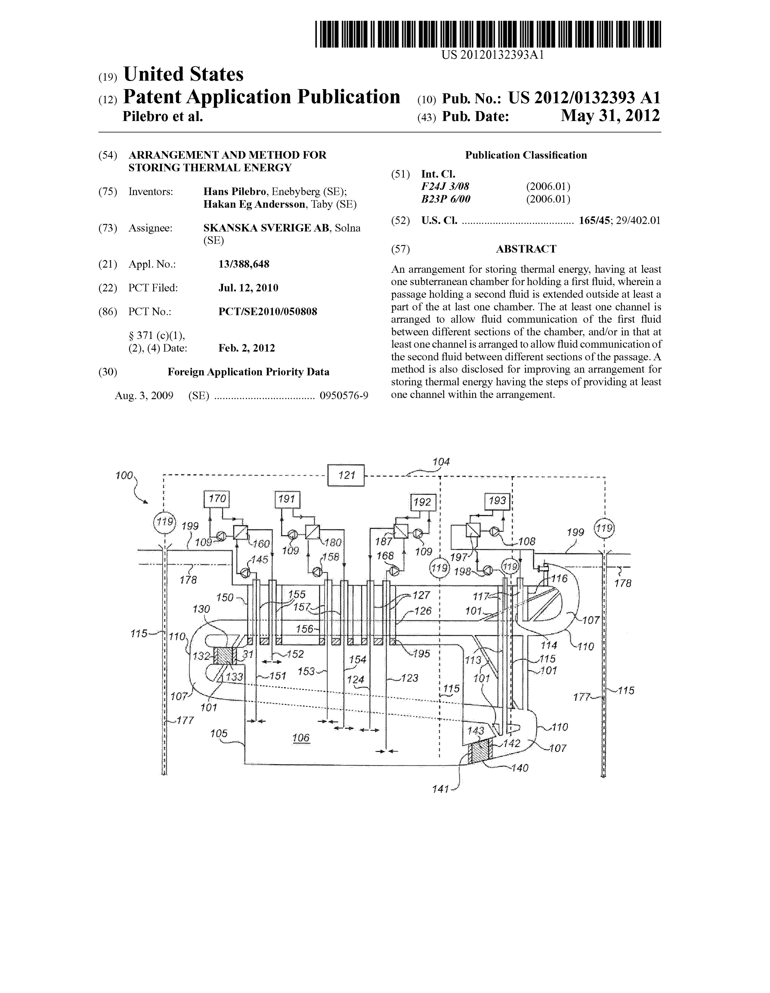
and the second concrete block 142 there is provided a suitable material 143. Such as gravel or soil, or a mixture of insulation 0099. According to a first example the energy source 170 and concrete or granulate concrete. is an electricity generator powered by fossil fuel. Such as 0092. Before commencing operation of the arrangement combustible oil or gas, or biofuel or biogas. 100, a desired amount of the first fluid 106 is provided to the 0100. According a second example the energy source 170 chamber 105. According to a preferred embodiment the first comprises Solar panels. Waste heat of the Solar panels may fluid 106 contains water. According to this example the first thereby be transferred to the first heat exchanger 160. fluid 106 is substantially filling up the chamber 105 during 0101. According a third example the energy source 170 operation of the arrangement 100. may be a condensing side of a heat pump. Whereas the cold 0093. The pressure of the first fluid 106 in the chamber 105 evaporator side of the heat pump could have an external heat is substantially in balance with the pressure of the surround Source. Such as air, sea water or an internal heat Source from ing ground water. The pressure of the second fluid 107 in the the storage.
Page 15
US 2012/0132393 A1 May 31, 2012
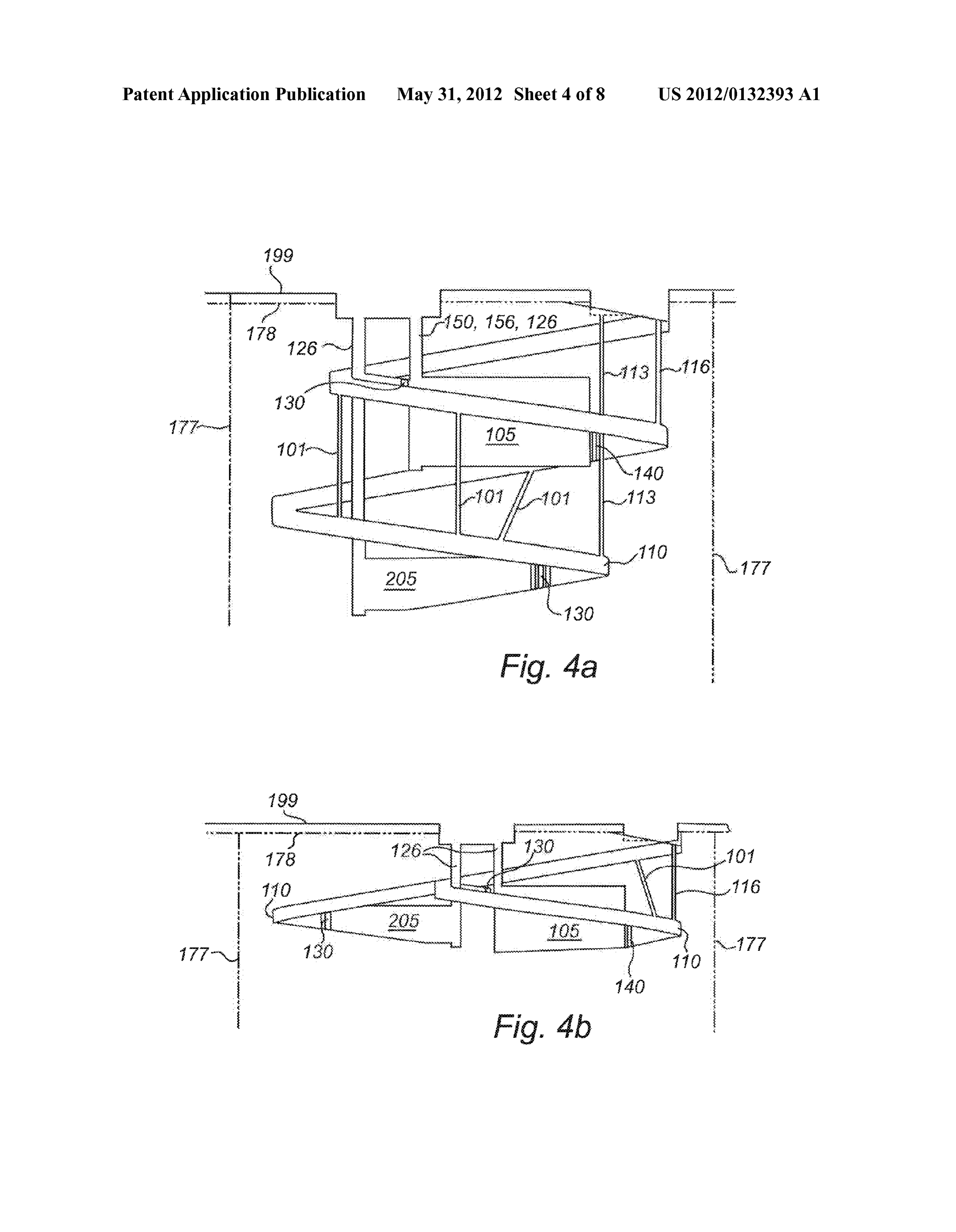
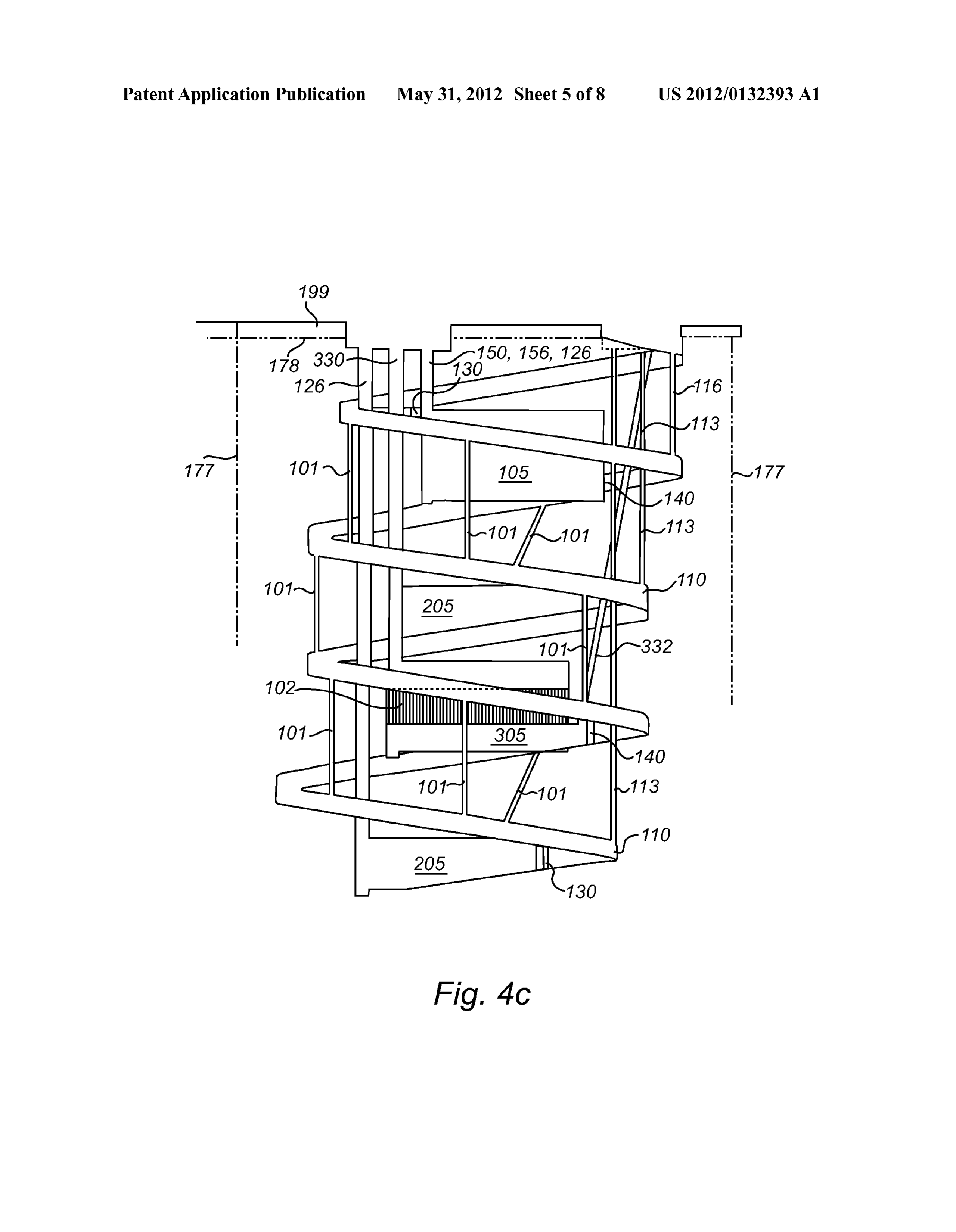
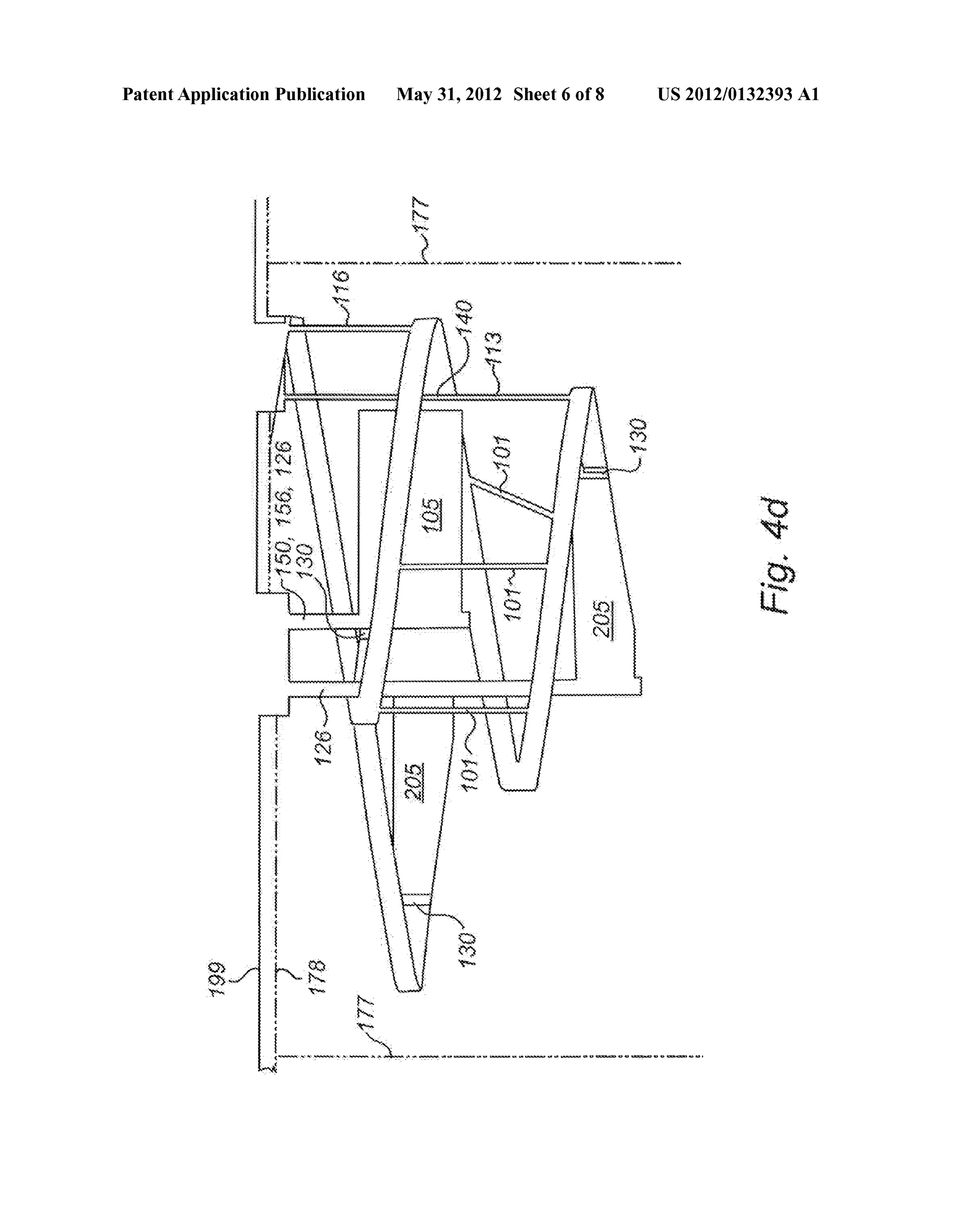
0102) According a fourth example the energy source 170 to perform a heat transfer process for cooling purposes. The comprises an internal heat source, which means that first fluid third fluid communication device 127 is arranged to return the 106 can be extracted from the chamber 105 at a vertical level processed first fluid 106 back to the chamber 105 at a suitable where the temperature is about 15-25 degrees Celsius and a vertical level.
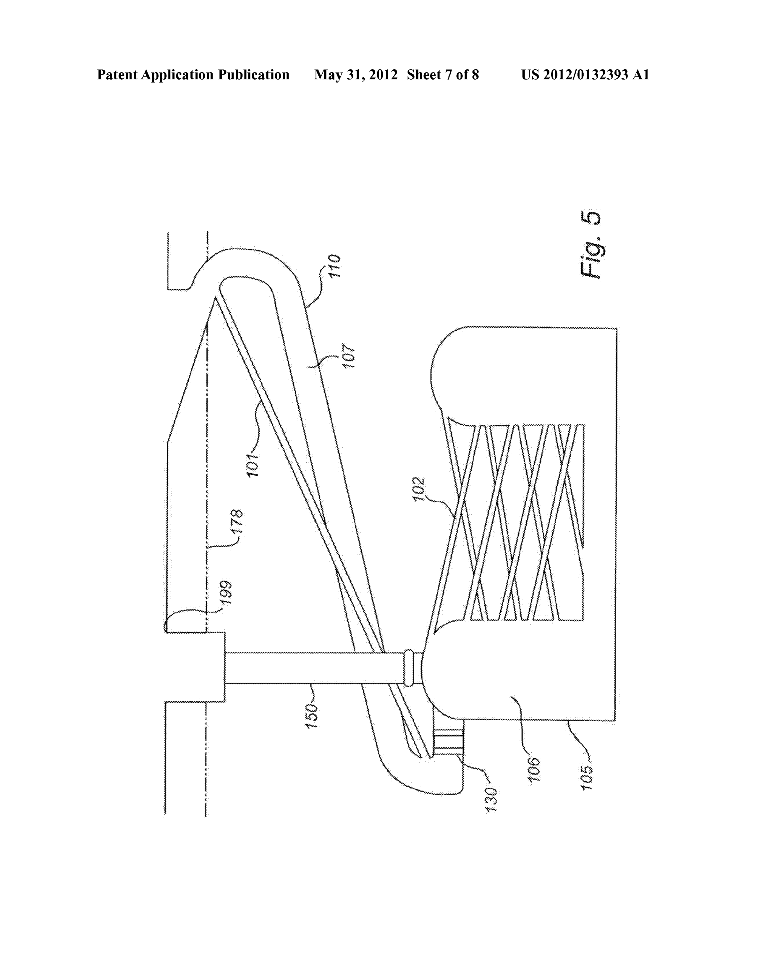
first portion is brought to the condensing side to be heated to 0107 The third heat exchanger 187 is in any suitable man a temperature of about 60 degrees Celsius and back to the ner connected to a second consumer unit 192. The second chamber 105 at an appropriate level. A second portion of the consumer unit 192 may be any arbitrary consumer unit. Such extracted first fluid 106 is brought to an evaporator side to be as a real estate, manufacture facility, hospital, etc. The second cooled to a temperature of about 10 degrees Celsius and back consumer unit 192 is arranged to use the arrangement 100 for to the chamber 105 at an appropriate level. cooling purposes. For example thermal energy of the arrange 0103) According to an aspect of the invention there is ment 100 may be used during a warm summer period to cool provided a second fluid communication device 157. The sec a building or factory (consumer unit 192). ond fluid communication device 157 may be substantially identical with the first fluid communication device 155. The 0108. According to one example the third fluid communi second fluid communication device 157 is arranged to, via a cation device 127 comprises a pair of telescopic pipes, which second shaft 156, extract a portion of the first fluid 106 from may be controlled mutually independent. A first pipe 123 of the chamber 105 and to provide the extracted portion of the the third fluid communication device 127 is arranged to first fluid 106 to a second heat exchanger 180. The second extract the first fluid 106 from the chamber 105 at an arbitrary heat exchanger 180 may be substantially identical with the vertical level. A second pipe 124 of the third fluid communi first heat exchanger 160. The second shaft 156 may have any cation device 127 is arranged to return the first fluid 106 at an Suitable dimensions. The second fluid communication device arbitrary vertical level in the chamber 105. 157 is also arranged to return the extracted first fluid 106 back 0109 According to an aspect of the invention there is to the chamber 105 at a suitable level. The second fluid communication device 157 may comprise a pump 158 being provided a fourth fluid communication device 117. The fourth arranged to pump the first fluid 106 from the chamber 105 to fluid communication device 117 may be substantially identi cal with the first fluid communication device 155. The fourth said second heat exchanger 180. The second heat exchanger 180 is arranged to perform a heat transfer process for heating fluid communication device 117 is arranged to, via a fourth purposes. The second fluid communication device 157 is shaft 116, extract a portion of the second fluid 107 from the arranged to return the processed first fluid 106 back to the passage 110 and to provide the extracted portion of the second chamber 105 at a suitable vertical level. fluid 107 to a fourth heat exchanger 197. The fourth heat 0104. The second heat exchanger 180 is in any suitable exchanger 197 may be substantially identical with the first manner connected to a first consumerunit 191. The consumer heat exchanger 160. The shaft 116 may have any suitable unit 191 may be any arbitrary consumer unit, Such as a house, dimensions. The fourth fluid communication device 117 is apartment, industry, real estate, manufacture facility, hospi also arranged to return the extracted second fluid 107 back to tal, etc. The consumer unit 191 is arranged to use the arrange the passage 110 at a suitable level. The fourth fluid commu ment 100 for heating purposes. For example thermal energy nication device 117 may comprise a pump 198 being arranged of the arrangement 100 may be used during a cold winter to pump the second fluid 107 from the passage 110 to said period to heat a building or factory (consumer unit 191). For fourth heat exchanger 197. The fourth heat exchanger 197 is example the arrangement is arranged to heat various kinds of arranged to perform a heat transfer process for heating and/or buildings. cooling purposes. The fourth fluid communication device 117 0105. According to one example the second fluid commu is arranged to return the processed second fluid 107 back to nication device 157 comprises a pair of telescopic pipes, the passage 110 at a suitable vertical level. which may be controlled mutually independent. A first pipe 0110. The fourth heat exchanger 197 is in any suitable 153 of the second fluid communication device 157 is arranged manner connected to a third consumer unit 193. The third to extract the first fluid 106 from the chamber 105 at an consumer unit 193 may be any arbitrary consumer unit, such arbitrary vertical level. A second pipe 154 of the second fluid as a real estate, manufacture facility, hospital, etc. The third communication device 157 is arranged to return the first fluid consumer unit 193 is arranged to use the arrangement 100 for 106 at an arbitrary vertical level in the chamber 105. cooling and/or heating purposes. For example thermal energy 0106. According to an aspect of the invention there is of the arrangement 100 may be used during a warm Summer provided a third fluid communication device 127. The third period to cool a building or factory (consumer unit 193). For fluid communication device 127 may be substantially identi example thermal energy of the arrangement 100 may be used cal with the first fluid communication device 155. The third during a cold winter period to heat a building or factory fluid communication device 127 is arranged to, via a third (consumer unit 193).
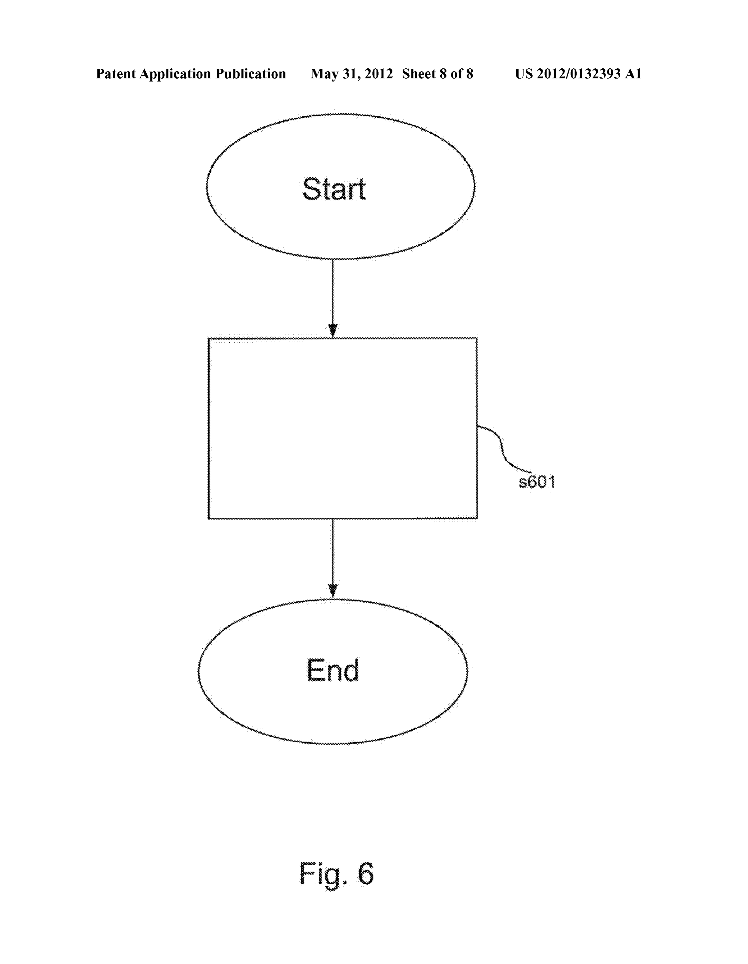
shaft 126, extract a portion of the first fluid 106 from the 0111. According to one example the fourth fluid commu chamber 105 and to provide the extracted portion of the first nication device 117 comprises a pair of telescopic pipes, fluid 106 to a third heat exchanger 187. The third heat which may be controlled mutually independent. A first pipe exchanger 187 may be substantially identical with the first 113 of the fourth fluid communication device 117 is arranged heat exchanger 160. The shaft 126 may have any suitable to extract the second fluid 107 from the passage 110 at an dimensions. The third fluid communication device 127 is also arbitrary vertical level. A second pipe 114 of the fourth fluid arranged to return the extracted first fluid 106 back to the communication device 117 is arranged to return the second chamber 105 at a suitable level. The third fluid communica fluid 107 at an arbitrary vertical level in the passage 110. tion device 127 may comprise a pump 168 being arranged to 0112 Alternatively the fourth fluid communication device pump the first fluid 106 from the chamber 105 to said third 117 is arranged to extract a portion of the second fluid 107 at heat exchanger 187. The third heat exchanger 187 is arranged one or more fix vertical levels of the passage 110. Similarly
Page 16
US 2012/0132393 A1 May 31, 2012
the second fluid communication device 157 is arranged to 0.121. The control units 119 and the central control unit return the second fluid 107 at one or more fix vertical levels of 121 are connected to each other via a network 104. The the passage 110. network 104 may comprise wires for communication pur 0113. It should be noted that different alternative configu poses. Alternatively the network 104 is a wireless network. rations of the inventive arrangement for storing thermal 0.122 The control units 119 may be connected to each energy is depicted herein. The different configurations com other for reciprocal action. A plurality of control units 119 prising one or more of the depicted arrangements may be may be controlled by a central control unit 121. According to provided with an arbitrarily number of fluid communication one embodiment the control units 119 is provided for moni means, shafts for the at least one chamber of the arrange toring data received from a plurality of temperature sensors ments, shafts for the passage of the arrangements, heat 115. According to one embodiment only one control unit 119 exchangers, energy sources, and consumer units. is provided for monitoring data received from a plurality of 0114. The different configurations comprising one or temperature sensors 115. According to one embodiment the more of the depicted arrangements may be provided with an central control unit 121 is provided for monitoring data arbitrarily number of channels being Suitable arranged to received from a plurality of temperature sensors 115. allow fluid communication of said first fluid between differ I0123. The at least one control unit 119 is arranged to ent sections of said chamber. The different configurations monitor temperatures at different locations and vertical levels comprising one or more of the depicted arrangements may be within the arrangement 100 and to display information provided with an arbitrarily number of channels being suit related to the different temperatures so as to allow an operator able arranged to allow fluid communication of said second to monitor the arrangement 100.
fluid between different sections of said passage. 0.124. The at least one temperature sensor 115 and the 0115 According to an embodiment of the invention there control unit 119 may be provided in any of the embodiments is provided pumping means 109, Such as a dry installed pump, depicted herein, e.g. with reference to FIG. 2, 3, 4a-d, and 5. each being arranged to pump the first or second fluid from a 0.125. The control unit 119 is arranged to store information heat exchanger 160, 180,187, 197 to the energy source 170, received from the at least one temperature sensor 115 in a or respective consumer unit 191, 192, 193. memory. The control unit 119 thus provides a logging func tion regarding temperature values being related to different 0116. It should also be noted that the one or more cham vertical levels within the arrangement 100. bers for storing the first fluid may be associated with one or I0126. According to one example the central control unit more passages holding a second fluid. For example, in case 121 is arranged to control various features of the arrangement two chambers are arranged vertically relative each other, each on the basis of said measured temperature values. For chamber may be associated with a separate passage. example the central control unit 121 is arranged to control the 0117. A ground water level 178 is indicated in FIG. 1. fluid communication means 155, 157, 127, 117, so as to set 0118. To minimize for inflow and outflow of ground water the pipes for extracting and returning the first or second fluid. from/to the ground water basin, a number of observation For example the central control unit 121 is arranged to control holes 177 is arranged to around the chamber 105. By regis various pumps within the arrangement 100, e.g. 145,158,168 tration of temperatures along the holes in Vertical direction, and 198, so as to regulate fluid flows within the arrangement unexpected thermal leakage due to outflow of warm water in a desired way. This may naturally be performed for any from the chamber can be observed. By controlling the ground embodiment depicted herein.
water level/pressure in the chamber 105 and the passage 110. I0127. According to an embodiment of the invention cool this outflow may be reduced. By pumping ground water in the ing and heating of the first fluid 106 requires an expansion observation holes 177 from an upstream side relative the Volume corresponding to the maximum temperature span in chamber to a downstream side thereof “ground water flow the chamber 105. The fluid balance of the inlet and outlet of thermal losses' can be further reduced. the first fluid 106 will be made from the bottom level of the 0119 Each shaft within any herein depicted arrangement chamber 105 to an uppermost portion of the passage 110. may be sealed close to the roof of the chamber so as to prevent I0128. To maintain the balance regarding the second fluid thermal circulation in the shaft. Each shaft may be sealed by 107 of the passage 110 the second fluid 107 will be balanced means of sealing means 195 for achieving thermal and liquid by extraction/refilling from a suitable level of the passage Sealing. 110. Advantageously a minimizing of thermal energy losses 0120 Four control units 119 are schematically illustrated associated with the first and second fluid is thereby achieved in FIG.1. A control unit 119 may be a computer, such as a PC. I0129. With reference to FIG. 2 there is schematically illus Each control unit 119 is arranged for communication with at trated an arrangement 200 for storing thermal energy, accord least one temperature sensor 115. The temperature sensor 115 ing to an aspect of the invention. Some elements of the may be arranged in the chamber 105, the passage 110 and/or arrangement 200 are depicted in greater detail with reference the bore hole 177. The temperature sensor 115 may thus be to FIG.1.
arranged to measure temperatures of the first fluid 106 at a 0.130. According to this example arrangement 200 for desired vertical level. The temperature sensor 115 may alter storing thermal energy a passage 110 and a chamber 205 are natively be arranged to measure temperature of the second provided. One difference between the arrangement 100 fluid 107 at a desired vertical level. The temperature sensor depicted with reference to FIG. 1 and the arrangement 200 is 115 may alternatively be arranged to measure temperatures of that the chamber 205 initially only had one entrance 130 the ground water provided in the bore hole 177 at a desired (initial inlet) provided by the passage 110 instead of two vertical level. The temperature sensor 115 is arranged to send entrances 130 and 140 (initial inlets). signals to the control unit 119. The control unit 119 is I0131) A plurality of channels 101 are provided in the arranged to receive signals comprising information about arrangement 200 according to the invention. The channels temperatures from at least one temperature sensor 115. 101 may be drilled by means of a drilling machine.
Page 17
US 2012/0132393 A1 May 31, 2012
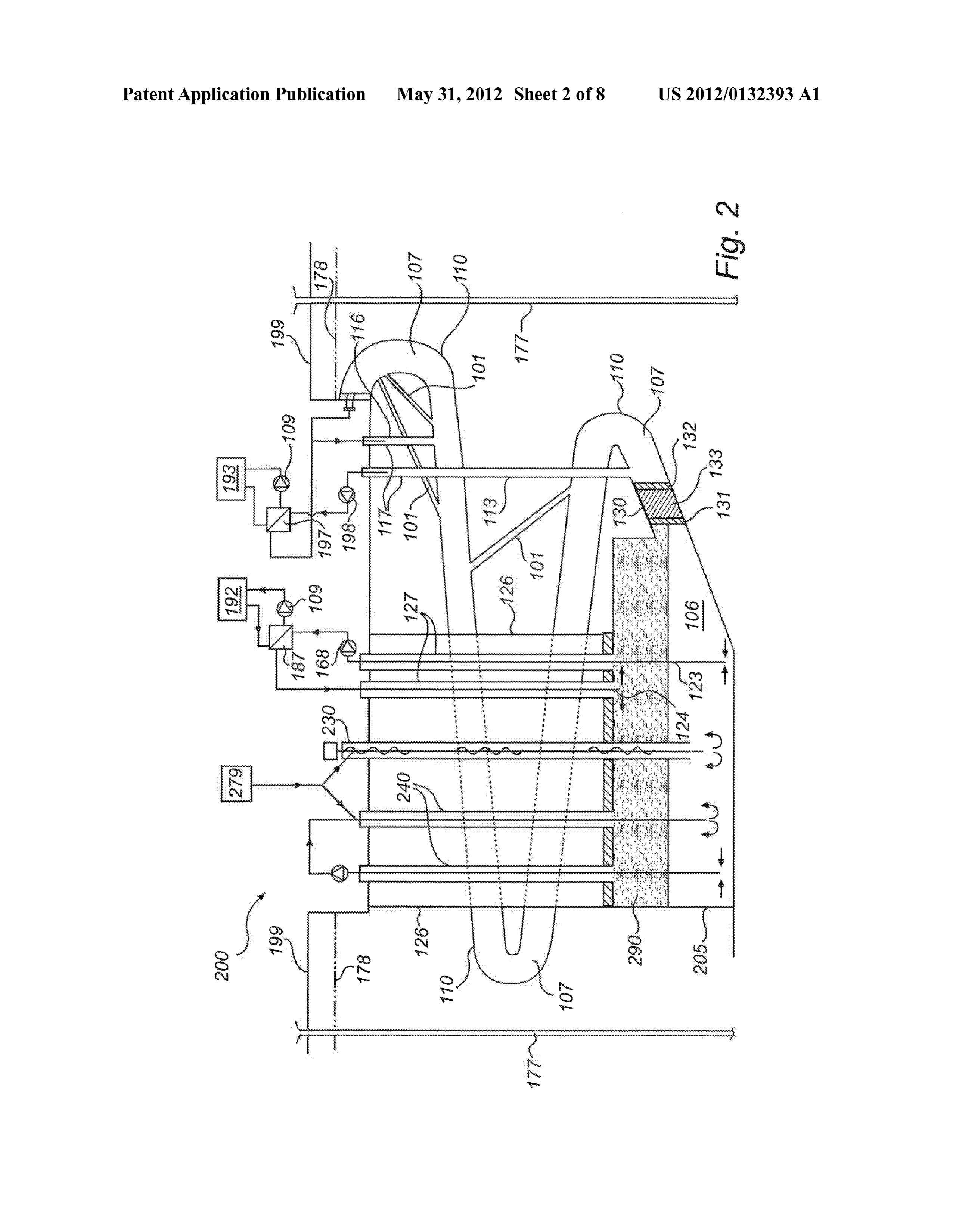
0.132. According to this example arrangement 200, stor level for extraction of the first fluid is of less importance in the age of a relatively cold first fluid 106 is desired. Also, accord arrangement 200, in particular in a case where the tempera ing to this example arrangement 200, storage of a relatively ture interval of the first fluid 106 is within a few degrees cold Second fluid 107 is desired. The first fluid 106 is stored in Celsius, such as e.g. 4-0 degrees Celsius. The third fluid a chamber 205. The second fluid 107 is stored in the passage communication device 127 may be arranged with a fluid 110. The first fluid 106 and the second fluid 107 are preferably extraction pipe being provided at a predetermined vertical used for applications including cooling, meaning that e.g. the level within the chamber 205. Accordingly, the third fluid third fluid communication device 127, is arranged to extract a communication device 127 may be arranged with a fluid relatively cold portion of the first fluid 106 and to provide this return pipe being provided at a predetermined vertical level portion to the third heat exchanger 187, so as to allow cooling within the chamber 205, preferably at a bottom of the cham of the second consumer unit 192. The third fluid communi
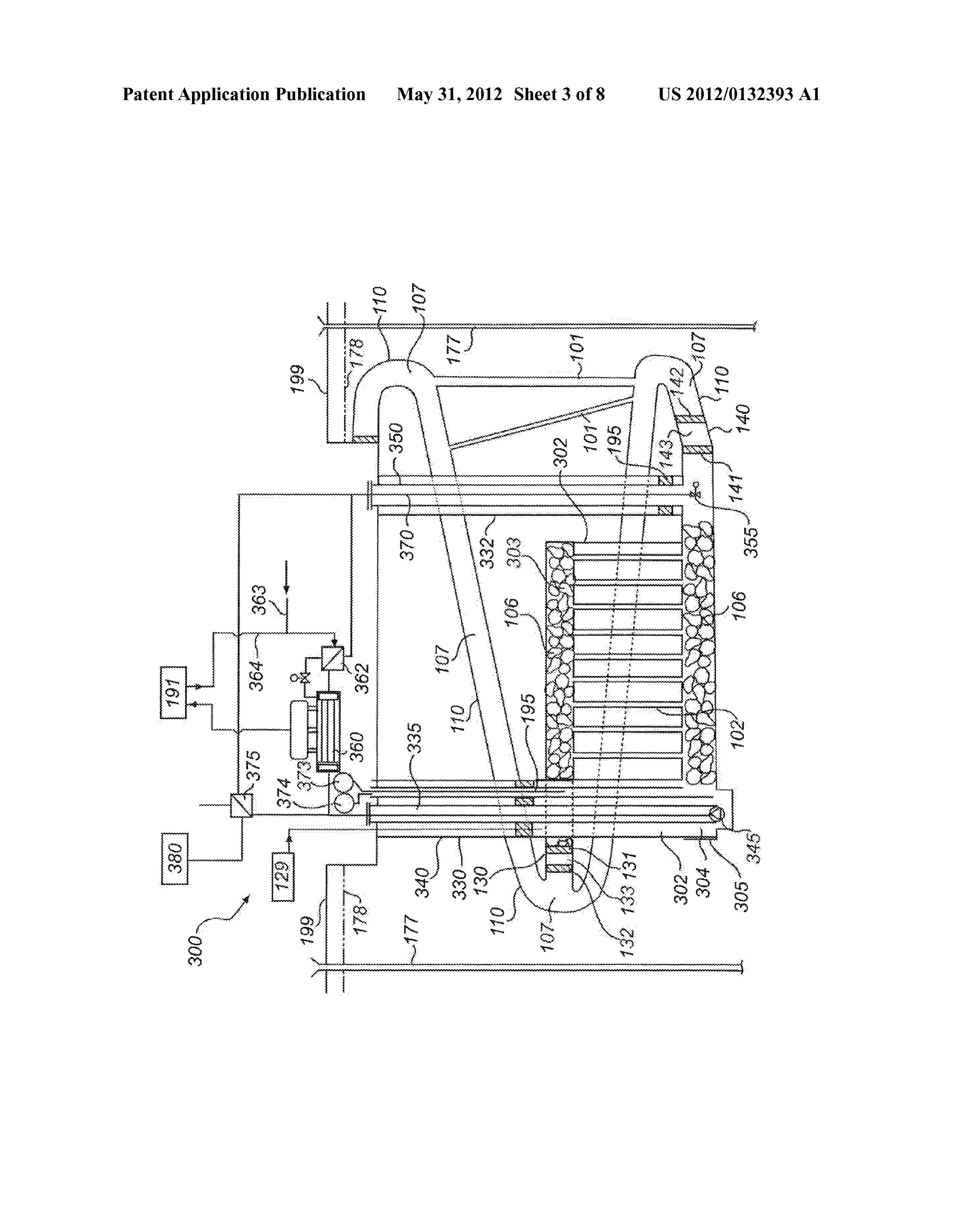
cation device 127 is arranged to return the processed portion of the first fluid 106 to the chamber 205. The processed 0.141. According to one example fractions of Snow depos portion of the first fluid 106 is typically warmer after being its containing Snow collected from roads or streets may be processed than when extracted. provided to the chamber 205 in any suitable manner. To avoid 0133. The chamber 205 is arranged to hold the first fluid undesired contamination of the first fluid 106 held in the 106 having a temperature of from -5 to 0 (ice) to +4 degrees chamber 205 purification procedures may be applied, so as to Celsius. The first fluid 106 may be in a solid phase. Ice is e.g. reduce a content of gravel or salt content of the Snow denoted by a reference number 290. In the case ice is provided before introduction to the chamber 205. it is located at an uppermost portion of the chamber 205. 0142. With reference to FIG.3 there is schematically illus Below the ice 290 a stable layer containing water having a trated an arrangement 300 for storing thermal energy, accord temperature of about 0–4 degrees Celsius is provided. ing to an aspect of the invention. Some elements of the 0134. An example where the first fluid is water follows. arrangement 300 are depicted in greater detail with reference 0135 According to one example the chamber 205 is to FIG. 1 and/or FIG. 2.
arranged to hold water having a temperature being within a 0143. The arrangement 300 comprises a chamber 305 range -5 to +15 degrees Celsius. Compared to a heated/ arranged to hold the first fluid 106. The passage 110 is holding cooled sensible water concept according to the arrangement the second fluid 107. The ground surface is indicated by 100 depicted with reference to FIG. 1 the arrangement 200 is reference numeral 199.
providing a similar thermal storage capacity preferably for cooling due to PCM (Phase Change Material) regarding 0144. A plurality of channels 101, 102 are provided in the Water. arrangement 300 according to the invention. The channels 0136. During operation of the arrangement for cooling 101, 102 may be drilled by means of a drilling machine. purposes, water may be extracted from a lower portion of the (0145 The chamber 305 is arranged with a first portion303 chamber 205 and returned to an upper portion of the chamber arranged to hold some of the first fluid 106. The first fluid 106 205 so as to thereby melt eventually provided ice. provided in the first portion 303 may have a temperature 0.137 According to one embodiment there is provided exceeding 100 degrees Celsius. According to one example the feeder means for providing ice and/or Snow from the ground temperature of the first fluid 106 of the first portion 303 is surface 199 to the chamber 205. According to one example within a temperature range 135-175 degrees Celsius. The first there is provided a motor operated feeder screw 230 for portion 303 is also referred to as an upper gallery. screwing down a suitable amount of ice and/or Snow. The 0146 The chamber 305 is arranged with a second portion feeder means may be arranged in a shaft, such as the third 304 arranged to hold some of the first fluid 106. The first fluid shaft 126, of the arrangement 200. The ice may be provided 106 provided in the second portion 303 may have a tempera by an ice machine (not shown). ture exceeding 90 degrees Celsius. According to one example 0138 According to one embodiment there is provided the temperature of the first fluid 106 of the second portion 304 alternative feeder means 240 for providing ice and/or snow is within a temperature range of 90-180 degrees Celsius. The from the ground surface 199 to the chamber 205. According second portion 304 is also referred to as a lower gallery. to one example there is provided a pump for providing a 0147 The arrangement 300 differs from the arrangement Suitable amount of ice and/or Snow via one or more pipes to 100 and 200 depicted above in that an intermediate layer 302 the chamber. This feeder means 240 is also arranged to extract is provided within the chamber 305 for storing the first fluid the first fluid 106 and mix the snow and ice to a slurry and 106. The intermediate layer 302 may be made of rock. The provide the slurry to the chamber 205. This feeder means 240 intermediate layer 302 is also referred to as rock section. A may also be arranged in a shaft, such as the third shaft 126, of plurality of channels 102 is provided to allow fluid commu the arrangement 200. The ice may be provided by an ice nication of the first fluid 106 between the second portion 304 machine 279. and the first portion 303. The channels 102 may be drilled 0.139. According to one embodiment there is provided a through holes between the first portion 303 and the second cooling means (not shown) for cooling the first fluid 106. The portion 304. The channels 102 are preferably substantially cooling means may comprise at least one cooling/freezing vertically arranged. An arbitrary number of channels 102 may loop. Alternatively, the cooling means may comprise at least be provided in the rock section. Each channel 102 may have one refrigerating pipe, Substantially being a cold element for an arbitrary Suitable dimension. According to one example a reducing the thermal energy of the first fluid 106 when being diameter of the channels is within a range of 10-20 centime provided therein. The cooling pipes may be removable held tres.
within the first fluid by any suitable means. (0.148. The first portion 303 may be at least partly filled by 0140. According to one example telescopic pipes for rock blocks. According to one example the first portion 303 is extracting water may not be used since a particular vertical completely filled by rock blocks. A porosity of the completely
Page 18
US 2012/0132393 A1 May 31, 2012
filled first portion may be about 30%. According to one steam vapour pressure. As the ambient rock gradually will be example the first portion 303 does not have any block rocks heated to the saturated Steam temperature, the vapour cushion provided therein. will gradually increase. A fully charged chamber will contain 014.9 The second portion 304 may be at least partly filled steam and heated rock at Saturated Steam temperature. by rock blocks. According to one example the second portion 0159. According to an embodiment, at discharging of 304 is completely filled by rock blocks. A porosity of the energy the level of the first fluid 106 will gradually increase, completely filled second portion may be about 30%. Accord exposing the first fluid 106 to heated rock surfaces and gen ing to one example the first portion 303 does not have any erating steam. This can be achieved at constant pressure in the block rocks provided therein. chamber 305. When a minimum steam cushion is reached in 0150. There is provided a shaft 330 between the ground the chamber 305, the stream pressure can gradually be surface 199 and the first portion 303 of the chamber 305. A reduced allowing for additional steam evaporation, by gradu first casing pipe 340 having a submerged pump 345 for pump ally cooling exposed rock Surface. The upper gallery of the ingaportion of the first fluid 106 from the first portion 303 via chamber 305 will act as a steam dome, separating liquid and a first pipe 335 to a heat exchanger 375. The pump 345 may be steam and to some extent Superheat the steam. arranged for extraction of the first fluid 106 from different 0160 According to an example, this operational mode levels. The first pipe 335 is provided within the casing pipe requires an external fluid balance corresponding to the maxi 340. The casing pipe 340 is arranged to pull up the pump 345, mum volume of steam in a fully charged chamber 305 and a e.g. for maintenance. minimum steam Volume/completely fluid filled heat storage. 0151. Alternatively a long shaft pump may be used for The fluid balance will however be made by use of the pump pumping the portion of the first fluid 106 from the first portion 345 so as to pump out a portion of the first fluid 106 from the 303 of the chamber 305 to the heat exchanger 375. The motor lower gallery 304 to an upper portion of the chamber 105 (see of the long shafted pump may be located in a machine room FIG. 1), or vice versa.
at the Surface. 0.161. In an alternative or complementary operation of the 0152 The first fluid 106 is provided to a steam generator arrangement 300 depicted above a cushion of saturated steam 360, which steam generator 360 is arranged to generate steam is maintained in the upper gallery 303 of the chamber 305. by means of thermal energy stored in the first fluid 106. The The first galley 303 may be filled with saturated steam at a first fluid 106 should be pressurized in the first pipe 335, heat temperature corresponding to the pressure in the chamber exchanger 175, and steam generator 360 so that the first fluid 305. A vertical level of the first fluid 106 may be adjusted by 106 is in a liquid phase. controlling an inlet or outlet flow of the steam. The arrange 0153. There is also provided a second pipe 370 for allow ment 300 may be provided with at least one fluid level sensor ing transport of the first fluid 106 from the steam generator 373 being arranged to detect the vertical level of the first fluid 360 to the second portion 304 of the chamber 305. The first 106. The fluid level sensor 373 may be connected to the fluid 106 is cooled of to some extent in the steam generator network 104 depicted with reference to FIG. 1. Data gener 360. The first fluid 106 is cooled of to some extent in a heat ated by the fluid level sensor 373 may be processed by any of exchanger 362. The heat exchanger 362 is arranged to preheat the control units 119 or the central control unit 121 depicted condensate 364 returning from a consumer unit, such as con with reference to FIG. 1 so as to allow control of any relevant Sumer unit 191 illustrated in grater detail with reference to feature of the arrangement, such as the pump 345 and the FIG. 1. Feed water 363 is provided to the returning conden Valve 355.
sate 364. The first fluid 106 should be pressurized within the 0162 The arrangement 300 may be provided with at least arrangement 300 by means of pump 345 during operation one fluid pressure sensor 374 being arranged to detect the thereof. pressure of the first fluid 106 within the chamber 305. The 0154 The second pipe 370 may be provided in a return fluid pressure sensor 374 may be connected to the network casing pipe 350, which is located in a second shaft 332. The 104 depicted with reference to FIG.1. Data generated by the return casing pipe 350 is provided with a pressure control fluid pressure sensor 374 may be processed by any of the valve 355 at the bottom of the chamber 305 at inlet 140. control units 119 or the central control unit 121 depicted with 0155 The heat exchanger 375 is connected to an energy reference to FIG. 1 so as to allow control of any relevant Source 380. Such as a standby power generator. The energy feature of the arrangement 300, such as the pump 345 and the source 380 is arranged to provide thermal energy to the heat Valve 355.
exchanger 375, which in turn is arranged to increase thermal 0163 The arrangement 300 may be controlled on the basis energy of the first fluid 106 extracted from the first portion of data detected by the fluid level sensor 373 and the fluid 303 by means of the pump 345 and the first pipe 335. pressure sensor 374 So as to regulate pressure of the steam 0156 According to a preferred embodiment the first fluid provided in the chamber 305 and vertical level of the first fluid 106 Stored in the chamber 305 is water. 106 in the chamber 305.
0157 During operation of the arrangement 300 and due to (0164. Theat least one fluid level sensor 373 and the at least thermal cycles, shear forces at the rock surface of the interior one fluid pressure sensor 374 may be integrated in any of the of the chamber 305 might cause scaling of the rock. As the embodiments depicted herein, e.g. with reference to FIG.1.2, upper 303 and lower 304 galleries according to an example 3, 4a-d and 5 are filled with rock blocks the volume of each gallery might 0.165 According to an example, operation pressure of the expand and the porosity thereof will be decreased. first fluid 106 is maximum 100 bar. 0158 According to an embodiment charging of energy (0166 It is with reference to FIGS. 4a-d below depicted will be performed by Supplying steam from an external steam various configurations of the inventive arrangement are illus generator 129 at the surface 199 to the top of the chamber 305. trated. It should be noted that the embodiments illustrated are The Supplied steam condensates at exposure to ambient rock for illustrative purposes. Naturally any suitable combination surfaces and the first fluid 106 at a lower temperature than the of shafts, fluid communication means, heat exchangers,
Page 19
US 2012/0132393 A1 May 31, 2012
energy sources, consumer units etc may be implemented. It 0179. It is illustrated that the passage 110 is extended should also be noted that any desired number of channels 102 outside the first chamber 105 and the second chamber 205. may be arranged in the arrangements illustrated to allow fluid The first chamber 105 and the second chamber are substan communication of said first fluid between different sections tially not in fluid communication with each other. of a chamber. It should also be noted that any desired number 0180 According to this configuration of the arrangement of channels 101 may be arranged to allow fluid communica for storing thermal energy the first chamber 105 is adjacent tion of said second fluid between different sections of the the second chamber 205.
passage 110. 0181. According to an alternative configuration of the (0167. With reference to FIG. 4a there is schematically arrangement for storing thermal energy the chamber 305 illustrated an arrangement for storing thermal energy, accord depicted with reference to FIG. 3 is arranged adjacent the ing to an aspect of the invention. chamber 105 depicted with reference to FIG. 1. 0168 The arrangement for storing thermal energy com 0182. According to an alternative configuration of the prises a first chamber 105 and a second chamber 205. The first arrangement for storing thermal energy the chamber 305 chamber 105 is depicted in greater detail with reference to depicted with reference to FIG. 3 is arranged adjacent the FIG. 1. The second chamber 205 is depicted with greater chamber 205 depicted with reference to FIG. 2. detail with reference to FIG. 2. The first chamber 105 and the 0183. According to an alternative configuration of the second chamber are arranged in a vertical configuration rela arrangement for storing thermal energy the chamber 105 tive each other. depicted with reference to FIG. 1 is arranged adjacent yet 0169. It is illustrated that the passage 110 is extended another chamber 105 depicted with reference to FIG. 1. outside the first chamber 105 and the second chamber 205. 0184. According to an alternative configuration of the The first chamber 105 and the second chamber 205 are sub arrangement for storing thermal energy the chamber 205 stantially not in fluid communication with each other. depicted with reference to FIG. 2 is arranged adjacent yet According to this configuration of the arrangement for storing another chamber 205 depicted with reference to FIG. 2. thermal energy the first chamber 105 is provided above the 0185. According to an alternative configuration of the second chamber 205. arrangement for storing thermal energy the chamber 305 (0170 Bore holes 177, also referred to ground water con depicted with reference to FIG. 3 is arranged adjacent yet trol units, are provided adjacent the first 105 and second 205 another chamber 305 depicted with reference to FIG. 3. chambers. The shafts 113, 116, 126, 150, and 156 are illus 0186 Bore holes 177, also referred to ground water con trated. Ground surface 199 and ground water level 178 are trol units, are provided adjacent the first 105 and second 205 illustrated. chambers. The shafts 116, 126, 150, and 156 are illustrated. 0171 According to an alternative configuration of the Ground surface 199 and ground water level 178 are illus arrangement for storing thermal energy the chamber 305 trated.
depicted with reference to FIG.3 is arranged above the cham 0187. With reference to FIG. 4c there is schematically ber 105 depicted with reference to FIG. 1. illustrated an arrangement for storing thermal energy, accord 0172 According to an alternative configuration of the ing to an aspect of the invention. arrangement for storing thermal energy the chamber 305 0188 The arrangement for storing thermal energy com depicted with reference to FIG.3 is arranged above the cham prises three chambers, namely the first chamber 105, the ber 205 depicted with reference to FIG. 2. second chamber 205 and a third chamber 305. The first cham 0173 According to an alternative configuration of the ber 105 is depicted in greater detail with reference to FIG. 1. arrangement for storing thermal energy the chamber 105 The second chamber 205 is depicted with greater detail with depicted with reference to FIG. 1 is arranged above yet reference to FIG. 2. The third chamber 305 is depicted with another chamber 105 depicted with reference to FIG. 1. greater detail with reference to FIG. 3. 0.174. According to an alternative configuration of the (0189 The first chamber 105, the second chamber 205 and arrangement for storing thermal energy the chamber 205 the third chamber 305 are arranged in a vertical configuration depicted with reference to FIG. 2 is arranged above yet as illustrated in FIG. 4c.
another chamber 205 depicted with reference to FIG. 2. 0190. It is illustrated that the passage 110 is extended 0.175. According to an alternative configuration of the outside the first chamber 105, the second chamber 205 and the arrangement for storing thermal energy the chamber 305 third chamber 305. The first chamber 105, the second cham depicted with reference to FIG. 3 is arranged above yet ber 205 and the third chamber 305 are substantially not in another chamber 305 depicted with reference to FIG.3. fluid communication with each other. 0176 According to an alternative configuration of the (0191) Any suitable combination of the first chamber 105, arrangement for storing thermal energy the chamber 205 the second chamber 205 and the third chamber 305 may be depicted with reference to FIG. 2 is arranged under the cham realized.
ber 105 depicted with reference to FIG. 1. 0.192 According to a preferred configuration of the (0177. With reference to FIG. 4b there is schematically arrangement for storing thermal energy the third module 305 illustrated an arrangement for storing thermal energy, accord is provided at an uppermost position, and the first chamber ing to an aspect of the invention. 105 is provided at an intermediate position between the sec 0.178 The arrangement comprises a first chamber 105 and ond chamber 205 and the third chamber 305. a second chamber 205. The first chamber 105 is depicted in (0193 Bore holes 177, also referred to ground water con greater detail with reference to FIG. 1. The second chamber trol units, are provided adjacent the first 105, second 205 and 205 is depicted with greater detail with reference to FIG. 2. third 305 chambers. The shafts 113, 116, 126, 150, and 156 The first chamber 105 and the second chamber are arranged in are illustrated. Ground surface 199 and ground water level a horizontal configuration. 178 are illustrated.
Page 20
US 2012/0132393 A1 May 31, 2012
(0194 With reference to FIG. 4d there is schematically fluid between different sections of said chamber; and/or pro illustrated an arrangement for storing thermal energy, accord viding at least one channel to allow fluid communication of ing to an aspect of the invention. said second fluid between different sections of the passage 0.195 According to this configuration of the arrangement separated in height. After the method step sé01 the method for storing thermal energy the arrangement comprises the first ends.
chamber 105 and the third chamber 305. The first chamber 0205 The foregoing description of the preferred embodi 105 and the third chamber 305 are arranged horizontally ments of the present invention has been provided for the relative each other and the second chamber 205 is arranged purposes of illustration and description. It is not intended to under the first chamber 105 and the third chamber 305. be exhaustive or to limit the invention to the precise forms 0196. It is illustrated that the passage 110 is extended disclosed. Obviously, many modifications and variations will outside the first chamber 105, the second chamber 205 and the be apparent to practitioners skilled in the art. The embodi third chamber 305. The first chamber 105, the second cham ments were chosen and described in order to best explain the ber 205 and the third chamber are substantially not in fluid principles of the invention and its practical applications, communication with each other. thereby enabling others skilled in the art to understand the 0.197 According to an embodiment of the invention each invention for various embodiments and with the various pressure within different chambers may be independently modifications as are Suited to the particular use contemplated. controlled. In particular this is desired in a case where the 1. An arrangement for storing thermal energy, comprising: chambers each contain mutually different kinds of the first at least one subterranean chamber for holding a first fluid; fluid 106, Such as oil, water and propane. Each pressure may a passage for holding a second fluid is extended outside at be controlled via Suitable means such as a pressure device in least a part of said at last one chamber, and combination with a valve arranged in a shaft associated with at least one channel arranged to allow fluid communication the chamber. of said first fluid between different sections of said 0198 According to an embodiment of the invention the chamber, or to allow fluid communication of said second pressure of the first fluid 106 and the second fluid 107 may be fluid between different sections of said passage. independently controlled. In particular this is desired in a case 2. The arrangement for storing thermal energy according to where the first fluid 106 and the second fluid 107 each com claim 1, wherein said sections of the passage are separated in prises mutually different kinds of fluids, such as oil and water. height, and/or wherein said sections of said at least one cham Each pressure of the first fluid 106 and the second fluid 107 ber are separated in height.
may be controlled via suitable means such as a pressure 3. The arrangement according to claim 1, wherein said device in combination with a valve Suitable arranged. passage is surrounding said at last one chamber. 0199 According to an embodiment of the invention the 4. The arrangement according to claim 1, wherein said at pressure of the second fluid 107 and the surrounding ground least one channel is a plurality of channels forming a fluid water may be independently controlled. Each pressure of the curtain outside said at least one chamber. second fluid 107 and the surrounding ground water may be 5. The arrangement according to claim 1, wherein said at controlled via suitable means such as fluid level control least one channel is vertically arranged between said sepa means for controlling the level of the ground water. rated sections of the passage.
0200 Bore holes 177, also referred to ground water con 6. The arrangement according to claim 1, wherein at least trol units, are provided adjacent the first 105 and second 205 one channel is arranged between said separated sections of chambers. The shafts 116, 126, 150, and 156 are illustrated. said passage at an angle relative a horizontal plane allowing Ground surface 199 and ground water level 178 are illus thermal natural convection, Such as an inclination between trated. 1:10 and vertical relative the horizontal plane. 0201 With reference to FIG. 5there is schematically illus 7. The arrangement according to claim 1, wherein said first trated a cross sectional view of a chamber 105 of the arrange and/or second fluid is chosen from a group comprising: water, ment 100 for storing thermal energy, according to an aspect of a mixture of water and a coolant, any liquid fuels, such as the invention. Alternatively the chamber 205 of the arrange hydrocarbons of fossil origin or biological origin (biofuel), ment 200 or the chamber 305 of the arrangement 300 may be salt solution, ammonia or other refrigerants. used to exemplify the set up according to FIG. 5. 8. The arrangement according to claim 1, wherein said 0202 According to this example the chamber 105 has a chamber is a cavern made in a rock. form allowing at least one channel 102 to be provided 9. The arrangement according to claim 1, wherein said between different sections of the chamber 105. The at least passage is configured as a helix.
one channel 102 may be a plurality of channels 102. The 10. The arrangement according to claim 1, further com channels 102 are arranged to allow fluid communication of prising at least a first fluid communication means arranged to said first fluid 106 between different sections of the chamber extract an arbitrarily portion of said first fluid from the cham 105. berata suitable vertical level so as to allow processing of said 0203 With reference to FIG. 6there is schematically illus first fluid by means of a first heat exchanger, wherein said first trated a flow chart depicting a method for improving an fluid communication means further is arranged to return the arrangement for storing thermal energy, wherein said processed first fluid to the chamber at a suitable vertical level. arrangement comprises at least one Subterranean chamber for 11. The arrangement according to claim 10, further com holding a first fluid, wherein a passage holding a second fluid prising an energy source coupled to said first heat exchanger, is extended outside at least a part of said at least one chamber, which first heat exchanger is arranged to increase thermal according to an aspect of the invention. energy of the first fluid.
0204 The method comprises a first method step sé01. The 12. The arrangement according to claim 11, wherein said first method step sé01 comprises the steps of providing at energy source is any of a group of energy sources comprising: least one channel to allow fluid communication of said first a thermal electrical power arrangement for heating and/or
Page 21
US 2012/0132393 A1 May 31, 2012
cogeneration of electricity and heat, a spare unit, such as e.g. second fluid by means of a second heat exchanger, wherein an emergency electricity generator, Solar panels for heating or said second fluid communication means further is arranged to Solar panels for combined electrical generation and heating, return the processed second fluid to the passage at a Suitable biofuel heater, oilfired boiler, or a boiler powered by fossil vertical level.
fuel or biofuel, such as pellet. 20. A Method for improving an arrangement for storing 13.-15. (canceled) thermal energy, comprising:
16. The arrangement according to claim 1, comprising two providing at least one Subterranean chamber for holding a or three chambers, wherein the passage holding the second first fluid, and a passage holding a second fluid extend fluid is extended outside at least a part of at last one chamber. ing outside at least a part of said at least one chamber; and 17. The arrangement according to claim 16, wherein said at forming at least one channel selected from the group of least one chamber is a first chamber and a second chamber a channel to allow fluid communication of said first fluid being separated and vertically arranged relative each other, between different sections of said chamber; and and wherein at least one of said first and second chamber is a channel to allow fluid communication of said second Surrounded by the passage holding the second fluid. fluid between different sections of the passage. 18. The arrangement according to claim 16, wherein said at 21. A Method according to claim 20, wherein the step of least one chamber is a first chamber, a second chamber and a providing at least one channel comprises the step of drilling third chamber being separated and vertically arranged rela said channel by means of a drilling unit Such as e.g. a rock tive each other, and wherein at least one of said first, second drilling machine.
and third chamber is surrounded by the passage holding the 22. A Method according to claim 20, wherein the step of second fluid. providing at least one channel comprises the step of: 19. The arrangement according to claim 1, further com applying a pipe constituting said channel by means of pipe prising a second fluid communication means arranged to jacking extract an arbitrarily portion of said second fluid from the passage at a Suitable level so as to allow processing of said

Provenance
- Collection
- Patents citing this work
- Original assignee
- Skanska Sverige AB
- Pages
- 21
- Method
- pdftotext (the PDF's own text layer) + pdftoppm 300dpi page scans
- Patent office record
- patents.google.com →
- Source
- Google Patents citing-documents table
- Inventors
- Hans Pilebro; Hakan Eg Andersson; Skanska Sverige AB
- Published
- 2012-05-31
- Transcribed from
- patentimages.storage.googleapis.com →