patent · US4139321
Rock channel heat storage
13 February 1979
Page 1 — bibliographic record
United States Patent (19) 11) 4,139,321 Werner 45) Feb. 13, 1979 (54) ROCK CHANNEL HEAT STORAGE 56) References Cited 76 Inventor: Frank D. Werner, Box SR9, Jackson, U.S. PATENT DOCUMENTS Wyo. 83001 2,828,681 4/1958 Smith ..................................... 62/2X 3,987,786 10/1976 Keyes et al.... ... 126/270 X (21) Appl. No.: 764,511 4,054,246 10/1977 Johnson ............................... 237/1 A Primary Examiner-Jacob Shapiro (22 Filed: Jan. 31, 1977 Attorney, Agent, or Firm-Nickolas E. Westman
Related U.S. Application Data A heat or cold storage system utilizing a plurality of
Division of ser. No. 579,492, May 21, 1975, Pat. No. channels dug directly into the earth and filled with rocks which are used to absorb heat or cold for storage, a part of such storage being the rocks themselves and a 51 Int. C.’................................................ F16L 1/00 (usually much larger) part being the adjacent earth. 52) U.S. C. .................................... 405/154; 405/131; Conduit connections are provided for carrying heat or 126/270; 165/45; 237/1 R cold to the rocks.
58 Field of Search ......................... 61/105, 50, 36 A;
165/45; 126/270 E, 271, 400; 237/1 5 Claims, 4 Drawing Figures
QSS
2. C 235 E. 2. -Z 232, Z g7.
N \ N\ NY N N. N. N N N. N.
W. N. N \a V. N. Y w N NN N N
Page 2
Drawing sheet — no readable text.
Page 3
Z2/27 s:-- 52, ses 2/ ÉE. sea s
Alliu? A \\ All AL (ANAAAM (WCalAAAAMAWACSE K. AYA
SCSC).
CSCC,
S-S O YYC /w se az assaaaaasa
aayaaaaaaaaaaayaara
a. 22. at W 4As SSYasasa A. Phar asarayalas areas
Page 4
and to the heating or cooling system of the structure to
ROCK CHANNEL HEAT STORAGE be heated or cooled. The ducts can be used in any de This is a division, of application Ser. No. 579,492, sired manner for heat distribution or cold distribution. filed May 21, 1975 now U.S. Pat. No. 4,024,910. In areas where the water table is not a substantial BACKGROUND OF THE INVENTION factor, the rock filled channels can be used as they are formed without any additional insulation or other ex . Field of the Invention pensive additions, except for being covered over after The present invention relates to the storage of heat or they have been filled. Heated or cooled air is circulated cold in substantial quantities over relatively long peri to the rocks for heat exchange. The sources of heated or ods of time. O cooled air may be solar heat collectors, or ambient air 2. Prior Art heat or cold collectors, or heat from industrial power With the recent emphasis on use of solar heat, in plants or other locations where an excess of heat is particular, the problems associated with storing such provided at times.
heat for use at a later time have become more apparent. Because large amounts of earth are in thermal contact The high cost of construction of storage devices has 15 with the rock-filled channels, earth participates in the minimized the effectiveness and utility of solar heat. heat storage. In the case of long duration heating or Likewise, storage of heat from any source as well as the cooling (a number of hours or days or longer), heat storage of "cold" or negative heat has been a problem. storage of the adjacent earth may equal or even greatly In general, large volumes of storage media are abso exceed the amount of heat stored in the rocks them lutely essential, and at the present time the costs of 20 selves.
providing storage devices of adequate size has proved Two forms of the invention are shown, providing to be a limiting factor. different heat flow patterns. Various configurations of In the prior art, the use of solid heat or cold storage course can be formed without departing from the scope media has been known. Likewise, in-ground storage, of the invention. The ability to provide the low cost where the ground itself has been used for heat or cold 25 channels easily constructed with existing excavating storage is shown in U.S. Pat. No. 3,262,493, where ducts equipment, and using the earth which is already present are buried directly into the ground. The undisturbed together with low cost rock fill increases the economic earth around the ducts is used for heat or cold storage. feasibility of utilizing low cost energy sources for heat Thus, high cost duct work is provided in the ground, ing or cooling.
which is expensive to install and also to maintain. A 30 In the case of a high water table, very difficult dig liquid is used for heat exchange, raising the costs of ging or other problem, the heat storage structure may construction even further. be built above or partly above the original grade line so The use of rock as a storage medium is shown in U.S. as to form a small hill.
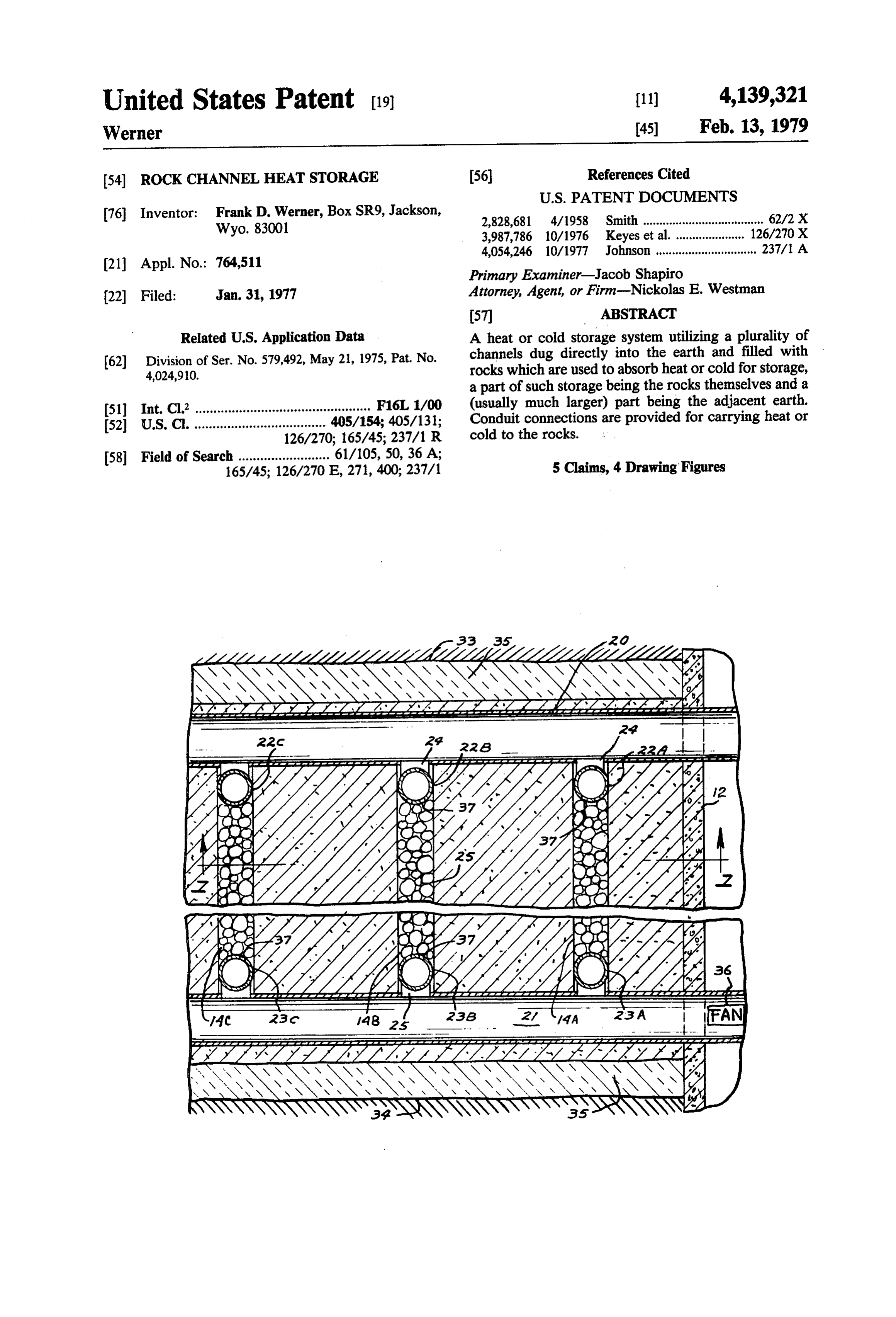
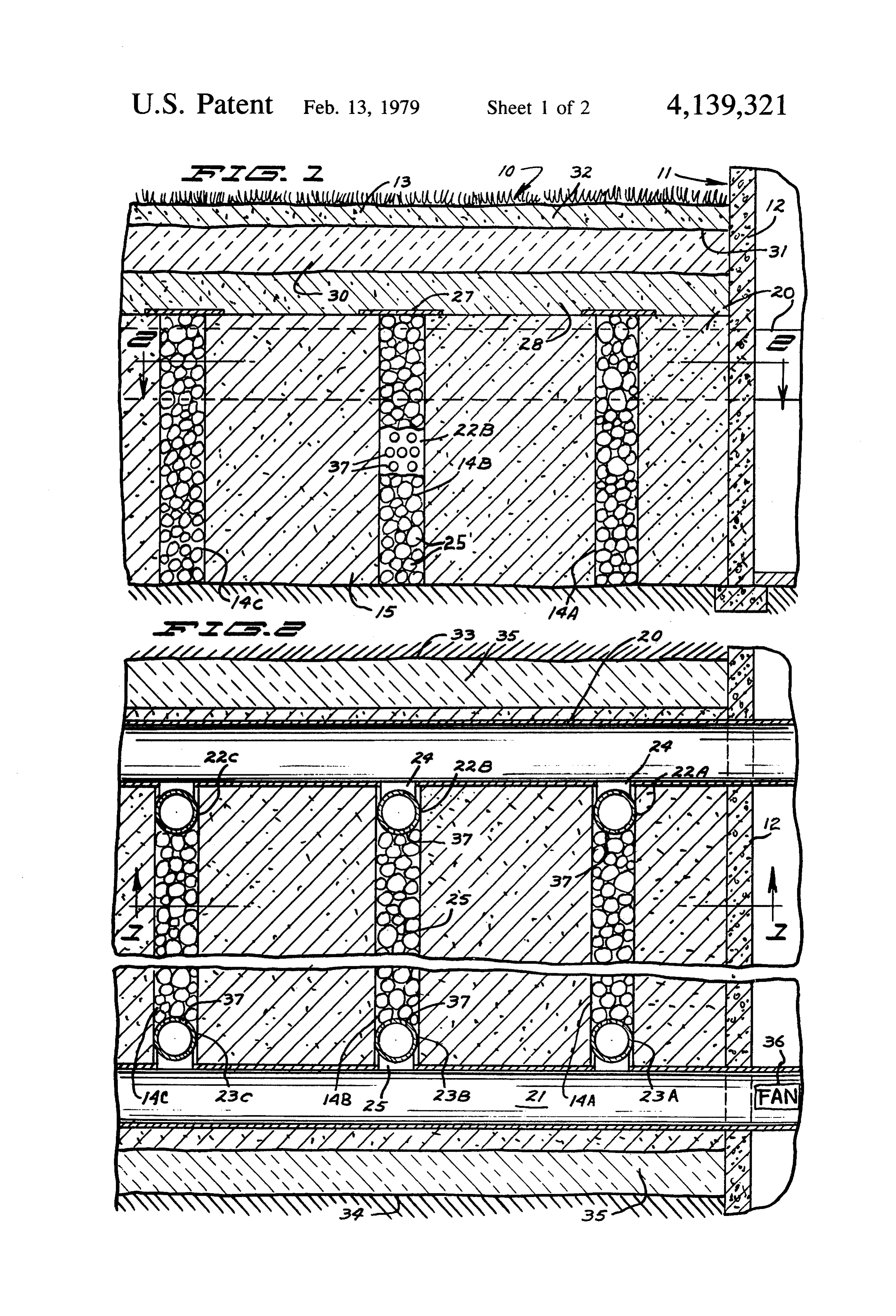
Pat. No. 2,680,565. A separate chamber inside a room or bin within the home being heated is used for the rock, 35 BRIEF DESCRIPTION OF THE DRAWINGS
Other devices utilizing solid material heat storage FIG. 1 is a part schematic vertical sectional view media are shown in U.S. Pat. No. 3,369,541 and through a section of earth showing the storage system 3,412,728. These patents are believed to be typical of made according to the present invention installed adja many others which use stones or sand within chambers cent to a building and taken as on line 1-1 in FIG. 2; or bins for heat storage. 40 FIG. 2 is a sectional view taken as on line 2-2 in In some cases, one is concerned that internal circula FIG.1;
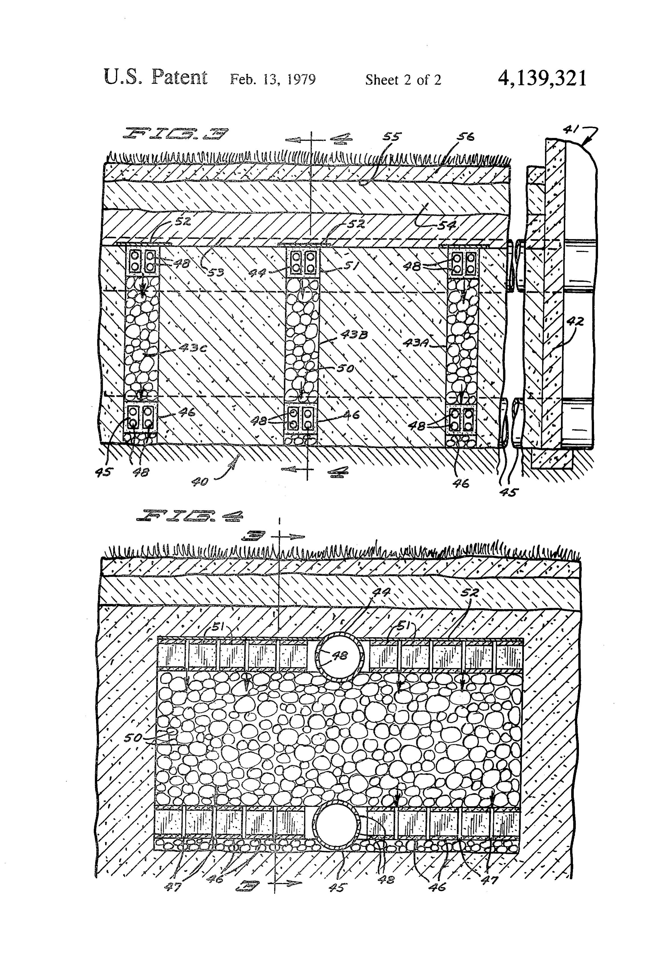
tion should not happen, such as a case where rocks in FIG. 3 is a vertical sectional view of a modified form one end of a channel are hot and are cold in the other of the invention taken as on line 3-3 in FIG. 4; and end. This is known and a preventative measure is FIG. 4 is a sectional view taken as on line 4-4 in known, of circulating the air vertically, as described in 45 FIG. 3.
Solar Energy Thermal Processes by Duffie, J. A., & DESCRIPTION OF THE PREFERRED Backman, W. A., John Wiley & Sons, Inc., 1974, p. EMBODIMENTS
SUMMARY OF THE INVENTION Referring first to FIG. 1, a heat storage area or bed 50 indicated generally at 10 is positioned adjacent the
The present invention relates to the provision of building 11. The building is shown merely for sake of channels dug directly in the ground with existing exca convenience, and the storage area 10 may be spaced a vating equipment and which are filled with rock to substantial distance from the building if desired. The provide a heat or cold storage medium in large quanti building wall 12 is shown below the grade line 13 of the ties that will permit the heating or cooling of occupied 55 ground.
structures in times of need. Adequate volume of storage In the construction of the heat storage system, (heat is material can be provided without exorbitant costs and used in its broad sense to include negative heat or cold) without providing above ground storage facilities. a plurality of channels as indicated at 14A, 14B, and 14C In its simplest form a trencher used commonly for are excavated into the ground in desired locations, to forming drain fields, septic systems, and also for shallow 60 desired depths and at desired widths. Excavation equip sewer work or a commonly available "back hoe" digger ment used for ditching can dig down to a depth of is used to dig a number of channels in desired locations twelve feet below the surface of the ground without any in the ground adjacent to the structure to be heated or problem. A typical width may be in the range of one cooled. The channels are then filled with rock or rock -foot, and the length can be practically any desired like material of suitable size and suitable connecting 65 length. The channels can be squared off fairly well ducts are placed in position as desired. Additional chan adjacent their side edges, and the bottoms can be nels may also be quicky dug if desired. These connect formed substantially planar without substantially dis ing ducts are then piped to the source of heat or cold, turbing the earth indicated generally at 15 between the
Page 5
channels. One such channel has been made and used The trenches 33 and 34 can be filled with other insula with horizontal airflow to store cold in winter for many tion, and/or water impervious material indicated gener months, with results generally as described herein. ally at 35, to surround the storage bed. This insulation If desired, the entire overlying area of the storage skirt or enclosure is merely an optional configuration area 10 can be excavated to a suitable depth before the 5 and in most instances it is not necessary unless the water channels are started to provide a space for insulation of table is high or other unusual problems exist. the channels if desired or the channels can be started at As shown schematically, a fan indicated at 36 can be the surface of the ground. Further, excavations at right provided in one of the ducts 20 or 21. This fan is for angles to the channels can be made adjacent the ends of either sending heated or cooled air into the storage the channels 14A, 14B and 14C for the installation of O media. Also, fans may be provided to pass air from the main supply and return ducts or pipes indicated gener atmosphere to the storage material for heat or cold ally at 20 and 21, in FIG. 2, which is a plan sectional storage.
view of the storage area. The ducts or pipes can then be areThe vertical distributor ducts 22A-22C and 23A-23C each provided with a plurality of apertures through installed in the side channels in a known manner and extended into the building 11 if desired. Further, as 15 the walls thereof. These apertures are indicated at 37, shown in FIG. 2 vertical distributor ducts or conduits and provide for a discharge of air or other fluid from indicated at 22A, 22B and 22C are installed adjacent one either one of the ducts 20 or 21 into the rock storage end of the respective channels 14A-14C, and vertical media, and also for exit of fluid from the other of the distributor ducts or conduits 23A, 23B and 23C are supply ducts.
installed at the opposite ends of the channels 14A-14C. 20 The ducts 22A-22C and 23A-23C extend vertically The distributor ducts extend for the vertical depth of along the ends of the channels 14A, 14B and 14C, re the channels and are contiguous to the rocks filling the spectively, so that fluid in these ducts will be discharged channels 14A-14C. The distributor ducts 22A-22C are along the vertical dimension of the channels 14A-14C. connected through short duct connector sections 24 to 25 The ducts 20 and 21 as shown are near the top of the the interior of one supply duct or pipe 20, and the verti channels 14A-14C, but they could be in the vertical cal distributor duct conduits 23A-23C are connected midportions, or near the bottom if desired. Further, the two ducts 20 and 21 do not have to be on the same level.
through duct connector sections 25 to the interior of the That conduit or pipe 21. The connections can be made in a is, one may be adjacent the top of the channels manner well known in sheet metal work, or plastic 14A-14C and the other adjacent the bottom of the ducts of known configuration also may be used. 30 channels if desired.
After the ducts have been installed as shown, the The fan shown schematically at 36 is merely for illus channels 14A, 14B and 14C, as well as other channels trative purposes. It can be understood that the heat that might be constructed are filled with discrete parti storage media comprising the rocks in the channels cles such as rock 25 of suitable size. After filling, the formed directly into the earth together with the adja channels 14A, 14B and 14C as shown extend to a level 35 cent earth can be used for storing solar heat; for storing slightly above the top of the ducts 20 and 21. When the heat from air conditioning units; or for storing excess channels 14A-14C have been filled with rock suitable heat from power plants in the summer, for example. The covers indicated at 27 can be placed over the tops of supply ducts can be connected in any desired manner these channels to prevent additional fill or other foreign for either heat storage or cold storage, and the removal material from getting into the spaces between the rocks 40 ofItcool air or hot air from the storage bed. is important to note how heat is exchanged bé in the channels. The loose rock provides a porous filler tween the earth and the rock filled channel. When heat for the channels 14A, 14B and 14C which filler has a high percentage of interstitial space through which air is being added rapidly, say for a few hours or less, only can readily pass. A layer of fill (sand or dirt) indicated a few inches of the adjacent earth is significantly heated. On the other hand, when heat is added over a long at 28 can be placed over the covers 27, and above that 45 period a layer of insulation such as sawdust, hay, or other low of time, either continuously or intermittently, a cost insulation and indicated generally at 30 can be considerable thickness of adjacent earth may be heated. placed. The depth of this insulation can range from When the period of heat addition lasts for several days three to twenty four inches, depending on the locality or several weeks or longer, all of the earth between the and type of use of the heat storage channel. Above this 50 channels may be heated significantly and store a major layer, a layer of polyethelene sheeting (or other water portion of the heat, even when the thickness of earth impervious sheet) indicated generally at 31 can be between channels is as great. as 4 to 10 feet or more. placed to provide a ground water barrier, and sod or Relatively small channel spacing is appropriate when other material indicated at 32 can be placed on top of short heat storage duration is important, and relatively the polyethelene so that the upper surface of the ground 55 great spacing is appropriate when very long heat stor resembles or is identical to the lawn or other ground age duration is involved. The same behavior exists surface adjacent the area where the channels 14A when heat is being removed. Further, these consider ations apply whether the problem is that of storing heat through 14C are dug.
Once the storage bed has been constructed as shown, or storing cold. Thus, the methods of heat storage dis the outer periphery can be insulated or protected from cussed here have particularly attractive features when water intrusion if desired by digging separate trenches relatively long term storage and removal are important, indicated generally at 33 and 34, which trenches would say at least a day or a few days, and especially when as meet at the end of the heat storage area (surround the long as several days, several weeks or even several area) and as shown may terminate at the building wall 2. months.
However the separate trenches could also be connected 65 In spite of this, not a great deal of heat is lost down between the first rock storage channel 14A and the ward or outward in the long term. This is partly because building if desired to completely surround the storage of the nature of soil and partly because of the nature of channels 14. long term transient heat conduction. Soil is not a good
Page 6
heat conductor, nor is it a good insulator. It has a fairly The ducts 44 and 45 are connected to ducts on the good heat capacity. For such materials, well known interior of the house, and suitable fans or other devices transient heat conduction theory provides some impor for circulating air through the ducts 44 and 45 can be tant results. Over a period of a few hours heat does not provided.
move very far into a layer of earth. Over a period of a The channels and the blocks 51 are then covered with few days or weeks, or even months, heat may move a suitable covers 52, and a layer of fill 53 can be installed number of feet into soil but at distances of 10 or 20 feet above these ducts if desired. Then a layer of insulation or more, many months are needed before significant material 54 can be provided as well as a polyethelene temperature changes are felt. For long term use, the sheet 55.
type of heat storage described herein behaves as if it 10 Sod or other material 56 then can be used for topping were losing heat rapidly downward and to the sides at off the storage bed or area so that it appears the same as first, and then more and more slowly as time goes on, so other adjacent areas of the ground. that after two or three years the heat loss rate is low. The advantage of the arrangement shown in FIGS. 3 One can view this as a result of the surrounding earth and 4 is that the heat or cold can be caused to remain having been slowly brought near the mean temperature 15 stratified. In some storage units using rock or other of the storage system, which suppresses heat loss. Also, media of large volume which permits air circulation the distance over which heat must be conducted be through the media, a natural convection will be set up. comes very great. Adjacent one end of the rock the warmer air will rise, Referring now to FIGS. 3 and 4, a modified form of and air will flow along the top of the storage area. A the invention is shown. In the modified form, the same 20 return flow passes down along the opposite side of the general construction is used, but a different distributionmedia and a return cross flow is formed at the bottom. system is utilized for circulating air to and from the This convection induced circulating flow tends to storage material. As shown, a storage area or bed indi equalize temperatures so that the medium in the enclo cated generally at 40 is adjacent to a house or building sure will tend to be maintained generally at a substan 41, which has a wall 42. The storage area or bed is made 25 tially equal temperature. Better heat exchange occurs up of a plurality of channels 43A, 43B and 43C dug with a larger temperature differential between the ex directly into the earth, as in the previous form of the change airflow and the medium, so it is desirable to invention. have stratified layers, with the hottest material at the The channels 43A-43C are connected by an upper top, and lower temperatures at the bottom. The form of conduit or duct 44 and a lower conduit or duct 45 both 30 the invention shown in FIGS. 3 and 4 permits this desir of which extend transversely to the channels. These able result to be achieved.
ducts may be installed by excavating another separate Thus, in this form of the invention, the cold air con channel at right angles to the channels 43A-43C and nection, whether cold air is being taken out or provided placing the ducts 44 and 45 in the separate channel. to the storage material, is at the bottom and thus duct 45 In constructing the storage system of this form of the 35 is the cold air duct. The hot air duct, whether heat is invention, after the channel 43A-43C (and any other being taken out or going into the storage medium chan additional parallel channels desired) have been formed, nels is at the top and the hot air duct is thus duct 44. and the cross channel or channels have been dug for Both of the ducts 44 and 45 can be at the ends of the installation of the supply and return ducts 44 and 45, the channels 43, or alternately both large ducts 44 and 45 lower duct 45 is placed into position in the midportions could be near the surface of the ground and separate of the channels 43 as shown (of course the duct 45 could ducts used to feed air to the blocks 46 of each channel be at either end of the channels 43 if desired) and a 43 so that cold air that was added to or removed from plurality of cinder or concrete blocks or tiles indicated the storage media would be still supplied at the bottom at 46 are laid in the bottom of each of the channels of the cross channels 43A-43C through the blocks 46. 43A-43C. The blocks 46 are spaced apart as shown at 45 Water barriers can be installed around the storage 47 for air circulation between the blocks. As shown, the bed 40 if desired. If ground water is a serious problem, duct 45 has a plurality of openings 48 through the wall the entire bed location can be excavated to form a large thereof on opposite sides thereof aligning with the chan hole and then the hole lined with polyethylene or suit nels 43A-43B so that the openings 48 open to the inte able waterproof material and refilled in the form shown, rior passageways of the respective blocks 46 on oppo 50 with the cross channels 43A-43C holding the porous site sides of the duct 45. The interior passageways of the rock being separated by filled layers of earth. blocks 46 and the aligning openings 48 can be seen in In addition, in other situations where water intrusion FG, 3. is a serious problem, for example because of a high The channels 43A-43C are then filled with rock of water table, or where digging is difficult, for example suitable size and the cross channel cut for installation of 55 because bed rock is at or near the surface, part or all of the duct 45 can be filled with earth between the chan the heat storage structure may be built above the origi nels 43. After the channels 43A-43C have been filled nal soil surface to form a small hill. In such cases only with the rock indicated generally at 50, the duct 44 is the lower part or none of the channels are formed by put in place and additional cinder or concrete blocks or digging operation; much or all of the intervening earth tiles 51 are placed across the top of each channel 43, and between channels is added by filling operations. Such are spaced apart. The duct 44 also has openings 48 in the earth material fill is generally cheaper and more avail wall thereof leading to the interior passageways of each able in properly sized rock, so that there are still advan of the blocks 51. Thus, the blocks 51 and 46 form trans tages over a simple rock bed in which substantially all verse passageways at the top and bottom of each chan heat is stored in such rock.
nel 43A-43C extending laterally outwardly from the 65 In FIGS. 3 and 4, the small hill or mound that is ducts 44 and 45. Flow passageways to the rock from the formed will be easily appreciated. The ground surface lateral passageways are also formed by the spaces be line is substantially along the bottom line of the chan tween the adjacent blocks 46 or 51. nels shown, and the fill in between channels is added
Page 7
material forming the hill or mound above the ground thick insulation and covering is advantageous. The surface. The connecting ducts at the break line of FIG. present system can be installed anywhere on a residen 3 for example are then connected into the channels in tial lot or other property, where channels can reason the hill in a suitable manner and can enter the building ably be dug. It is relatively insensitive to elevation, either below the ground surface as shown, or above the exposure to the sun or shade, etc. Further, it can leave ground surface if desired. landscaping relatively undisturbed, since grass and A simple way to build the heat storage system above small shrubbery can be installed directly above the ground or partly above ground, when an adequate storage system.
quantity of fill is economically available nearby, is to It is interesting and for some cases, important to ob use this fill to make a mound. It is then packed or al O serve that when cold is being stored, the channel struce lowed to settle and channels are dug and filled with ture is generally warmer than the incoming air. This rock in the usual way. causes a marked tendency for any water present in the Only one cross channel is necessary in the present channels (whether liquid or frozen) to be evaporated devices, but as many channels as necessary may be used. and carried away by the circulating air. The channels The rock used may be crushed rock or 'pea' rock of 15 and surrounding earth tend to dry out thoroughly. This suitable size, such as that used for driveways or for tends to reduce heat storage capacity somewhat, and drain fields. Rock ranging from inch or so in major reduces or eliminates possibility of frost or snow plug dimension (diameter) up to about six inches in major ging the interstices between rocks.
dimension, or even larger in some instances will work. Conversely, when heat is stored the channels are The rocks have to be of size to provide spaces for free 20 cooler and will condense moisture out of the air unless flow of air around and between them. Small sizes facili its dew point is below the rock temperature. This can tate rapid addition or removal of heat but require more result in water condensation in the bed, raising its stor horsepower to force air through. Large sizes are more age capacity. Excess water would merely drain away. appropriate for cases of slow heat addition or removal. Should this mode of operation take place at tempera This storage system has utility with respect to storing 25 tures below freezing, then trouble could result due to heat from solar heat collectors as previously stated. frost or ice freezing in the interstices. Another significant use is in connection with a heat What is claimed is:
pump (more or less an ordinary air conditioning system 1. The method of forming a heat or cold storage which is arranged for convenient reversal so that it may arrangement comprising the steps of forming at least either heat or cool the interior of a building). In use with 30 one channel between earth material layers, said channel a heat pump, in the summer, a fan or blower can be used being substantially upright and having an upright di to rapidly circulate cold air through the storage me mension substantially greater than its horizontal width dium whenever the outside air temperature is suffi and having a preselected length, placing perforated ciently cool so that heat may be removed from the fluid carrying ducts which substantially span the hori storage medium. This would most likely happen at zontal width of the channel at spaced locations
night though, perhaps, not every night, and therefore channel, filling said channel between said ducts inwith said
the ability to store sufficient heat (cold) for some days of service is highly desirable. the ability to store heat suffi material comprising discrete solid particles having sub cient for weeks or even a few months appears practical stantial interstitial spaces, and connecting said ducts to with the present arrangement. Thus, when there is a through means to circulate fluid from one duct to the other high air conditioning demand, heat is rejected from the the interstitial spaces. house or building into the storage medium rather than ing2.aThe method of claim 1 wherein the steps of form channel comprises digging the channel directly in into the relatively warm outside air. This substantially reduces losses in the air conditioning equipment for two the earth below the surface of the ground. reasons: (1) Air conditioners are more efficient when 45 3. The method of claim 2 including the method of the temperature difference against which they work is digging a separate trench spaced from and surrounding reduced; and (2) less work is needed to move heat from desired portions of said first mentioned channel, and a building to a reservoir near the building temperature filling said trench with an insulation material. (the storage medium) rather than to an environment 50 4. The method of claim 1 including the step of over whose temperature is farther away (the outside ambient laying said channel with a layer of insulating material, air). In winter, the reverse arrangement is used. The pervious and covering said insulating material with a water im heat pump is reversed. layer.
Where the bed is designed for only a few days heat or 5. The method of claim 1 wherein the step of forming cold storage capacity, very little insulation or fill above said channel comprising the digging of said channel the channels is necessary. For the cases where many 55 with excavation equipment used. days or many weeks heat storage is desired, relatively as a
Provenance
- Collection
- Cited prior art
- Original PDF
- patentimages.storage.googleapis.com →
- Filed
- 1977-01-31
- Pages
- 7
- Method
- pdftotext (the PDF's own text layer) + pdftoppm 300dpi page scans
- Source
- Google Patents bibliographic record
- Granted
- 1979-02-13
- Inventors
- Frank D. Werner
- Transcribed from
- patentimages.storage.googleapis.com →