patent · US4286574
Trickle-type thermal storage unit
1 September 1981
Page 1
United States Patent 19 11 4,286,574 Vrolyk et al. 45 Sep. 1, 1981 54) TRCKLE-TYPE THERMAL STORAGE UNIT 4,137,898 2/1979 Koizumi ............................... 126A-36 4,194,496 3/1980 Karlson ............................ 165/104 S 75 Inventors: John J. Vrolyk, Northridge; Ronald
P. Pauckert, Canoga Park, both of FOREIGN PATENT DOCUMENTS
Calif. 24094.63 7/i979 France ..................................... 126/900 73) Assignee: Rockwell International Corporation,
El Segundo, Calif. Primary Examiner-Albert W. Davis
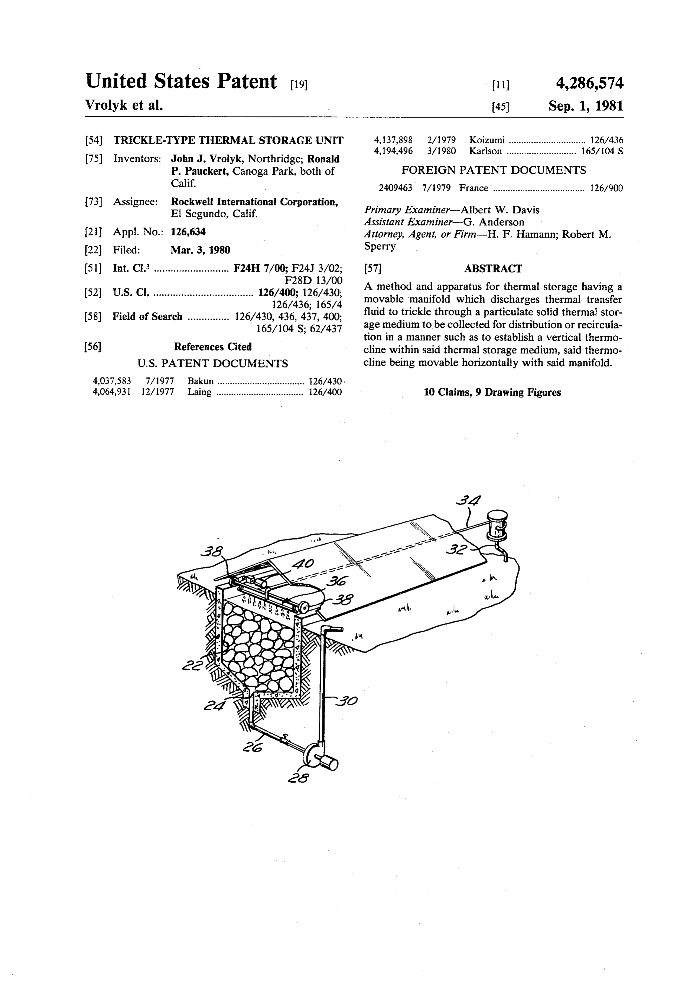
Assistant Examiner-G. Anderson 21 Appl. No.: 126,634 Attorney, Agent, or Firm-H. F. Hamann; Robert M. 22 Fed: Mar. 3, 1980 Sperry (51 Int, C. ........................... F24H 7/00; F24J 3/02; 57 ABSTRACT F28ED 13/00 A method and apparatus for thermal storage having a 52 U.S. C. .................................... 126/400; 126/430, movable manifold which discharges thermal transfer 126/436; 165/4 fluid to trickle through a particulate solid thermal stor
165/104 S; 62/437 age medium to be collected for distribution or recircula tion in a manner such as to establish a vertical thermo 56) References Cited cline within said thermal storage medium, said thermo
4,064,931 12/1977 Laing ................................... 126400 10 Claims, 9 Drawing Figures
Page 2
Drawing sheet — no readable text.
Page 3
Drawing sheet — no readable text.
Page 4
valving required for charging and extraction is quite
TRCKLE-TYPE THERMAL STORAGE UNIT simple.
Accordingly, it is an object of the present invention
BACKGROUND OF THE INVENTION to provide an improved method and apparatus for ther 1. Field of the Invention mal storage.
Another object of the present invention is to provide
This invention relates to thermal storage methods and a method and apparatus for thermal storage requiring apparatus, and is particularly directed to thermal stor minimal quantities of thermal transfer fluid. age methods and apparatus whereby a movable mani An additional object of the present invention is to fold discharges a thermal transfer fluid, such as silicone 10 provide a method and apparatus for thermal storage oil, to trickle through a particulate solid thermal storage requiring only a single tank and relatively simple valv medium, such as a quantity of rocks, and to be collected 1ng.
thereafter for distribution or for recirculation in a man A specific object of the present invention is to pro ner such as to establish a vertical thermocline within vide a method and apparatus for thermal storage having said thermal storage medium, said thermocline being 15 a movable manifold which discharges thermal transfer movable horizontally with said manifold. fluid to trickle through a particulate solid thermal stor 2 Description of the Prior Art age medium to be collected for distribution or for recir In the current search for alternative sources of en culation in a manner such as to establish a vertical ther ergy, considerable attention has been devoted to solar mocline within said thermal storage medium, said ther energy. Various techniques have been proposed for 20 mocline being movable horizontally with said manifold. converting solar energy into thermal energy. Unfortu These and other objects and features of the present nately, the prior art has taught no satisfactory method invention will be apparent from the following detailed for storing thermal energy. description, taken with reference to the accompanying U.S. Pat. No. 3,369,541, issued Feb. 20, 1968 to Harry drawings.
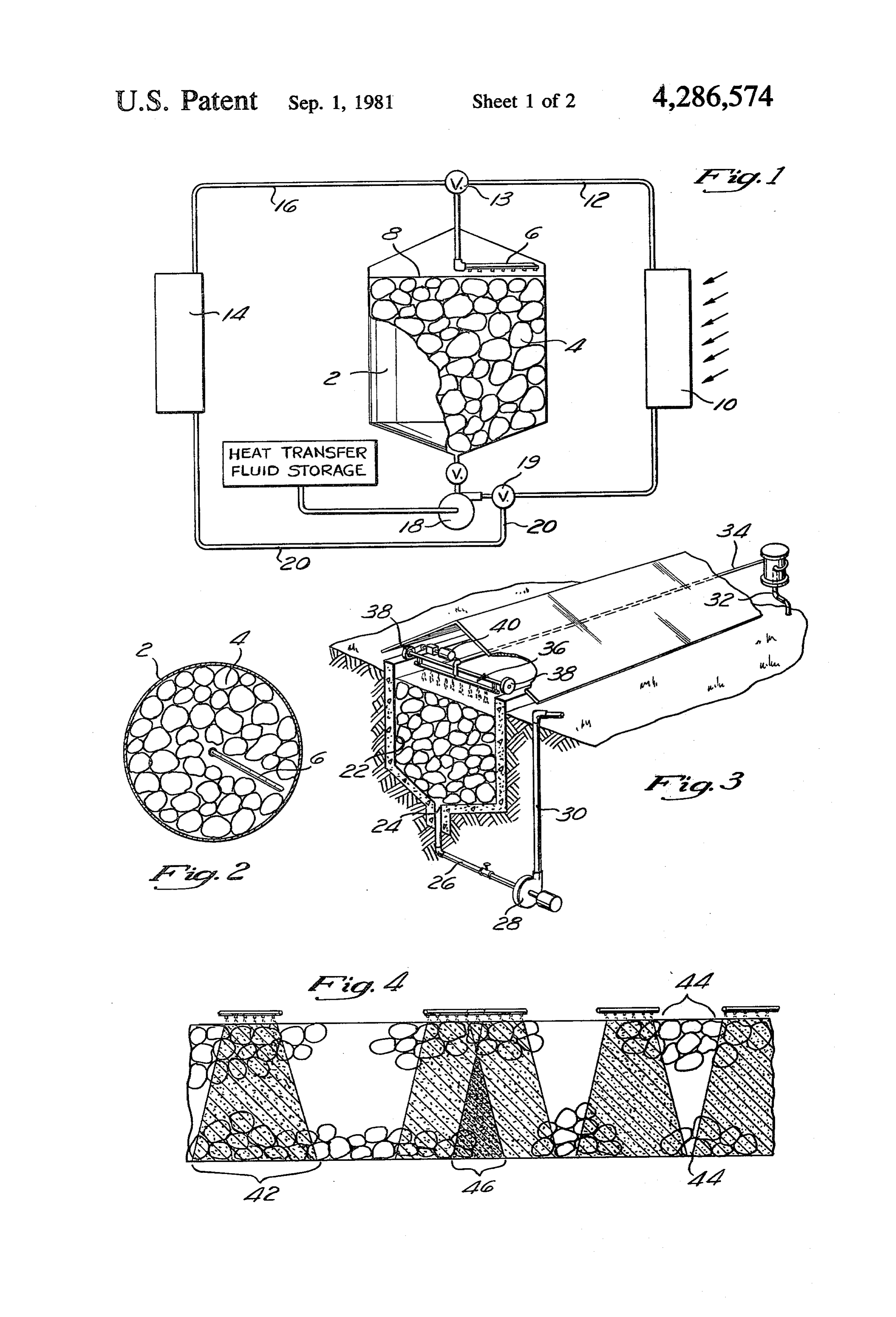
E. Thomason, discloses a prior art thermal storage sys 25 BRIEF DESCRIPTION OF THE DRAWINGS tem. However, in this system the liquid does not travel FIG. 1 is a diagrammatic representation of a rotary through the solid medium and does not provide a defini tive thermocline. thermal storage system embodying the present inven U.S. Pat. No. 4,010,731, issued Mar. 8, 1977 to Henry tion;
FIG. 2 is a plan view of the thermal storage system of
Harrison, teaches a thermal storage system in which 30 FIG.
heat rises to the top of the solid medium only by con 1;
vection. Moreover, a large quantity of thermal transfer gular FIG. 3 is a diagrammatic representation of a rectan fluid is required for Harrison's system, since he requires invention;thermal storage system embodying the present that the fluid completely fill all spaces between the solid 35 FIG. 4 is a diagrammatic representation showing the medium.
U.S. Pat. No. 4,037,583, issued July 26, 1977 to Paul dispersion mal storage pattern for fluid trickling through the ther medium of the thermal storage system of
Bakun, teaches a thermal storage system employing separate manifolds for charging and extracting fluid. FIG. 1;
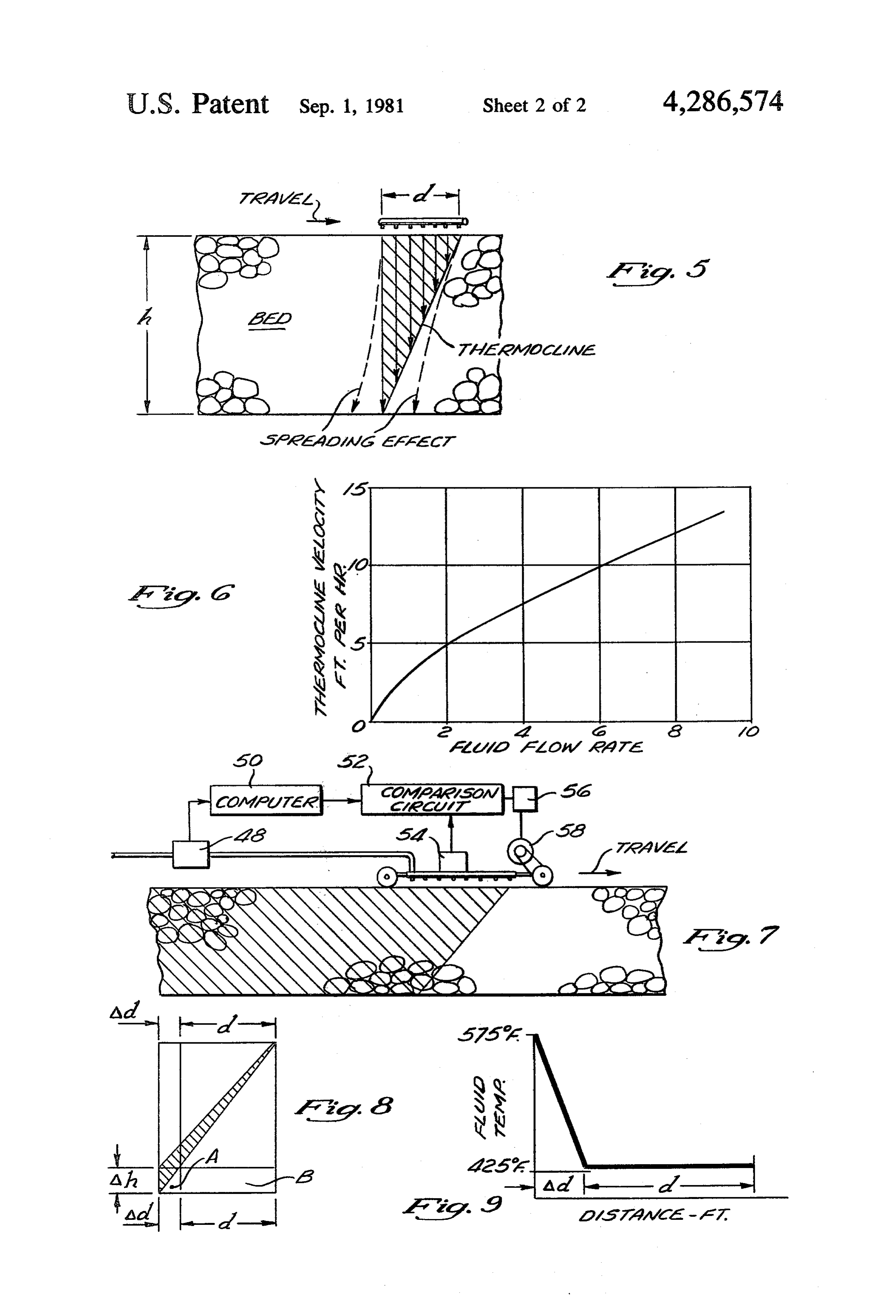
FIG. 5 is a diagrammatic representation showing the
This requires that heat travel sideways through the bed establishment of a vertical thermocline in the thermal by natural conduction and convection. This system also storage system of FIG. 1;
requires a large quantity of thermal transfer liquid and it appears unlikely that this system would provide a ther theFIG. fluid 6 is a curve showing the relationship between flow rate and the thermocline velocity in the mocline. thermal storage system of FIG. 1; U.S. Pat. No. 4,059,226, issued Nov. 22, 1977 to 45 FIG. 7 is a diagrammatic representation showing a David L. Atkinson, teaches a thermal storage system system for automatically positioning the fluid distribu that uses only air and rocks. No liquids are used. This tion manifold of the thermal storage system of FIG. 3; system must be completely charged with heat before FIG. 8 is a diagrammatic representation showing the any heat can be withdrawn. The Atkinson system diffuse zone of the thermocline of the thermal storage would appear to be expensive, since it requires a plural 50 system of FIG. 3; and ity of tanks together with the piping and valves neces FIG. 9 is a curve showing the relationship of fluid sary to guide the heat transfer fluid to the appropriate temperature to distance behind the fluid distribution tank. manifold of the thermal storage system of FIG. 3. BRIEF SUMMARY AND OBJECTS OF THE DETAILED DESCRIPTION OF THE
INVENTION PREFERRED EMBODIMENT
These disadvantages of the prior art are overcome In that form of the present invention chosen for pur with the present invention and a thermal storage system poses of illustration in FIGS. 1 and 2, the thermal stor is provided having a movable manifold which dis age system comprises a tank 2 filled with a particulate charges a thermal transfer fluid to trickle through a 60 thermal storge medium 4, such as rocks, and a rotating particulate solid thermal storage medium, such as a spray head 6, similar to that used in aerating water at a quantity of rocks, to be collected thereafter for distribu sewage plant. In accordance with the present invention, tion or for recirculation in a manner such as to establish a relatively small quantity of a suitable thermal transfer a vertical thermocline within said thermal storage me fluid 8, such as silicone oil, is heated by suitable heating dium, said thermocline being movable horizontally with 65 means 10 and is delivered via conduits 12 and three-way said manifold. valve 13 to the spray head 6 which allows the heated This system requires only minimal quantities of ther fluid 8 to trickle over the rocks 4 at a flow rate substan mal transfer fluid and only a single tank. Moreover, the tially determined by the gravity head. This serves to
Page 5
heat a small area of the rocks 4, from the top down and h\d=vt/vm. For a given bed, h and d are relatively Ward, until a vertical thermocline is established in this fixed and v is a function of the flow, rate and other area. When this is accomplished, the spray head 6 is relatively constant parameters. Thus, the manifold ve moved and the process is repeated until the entire bed of locity is Vn = d/hvi, and V is a function of the following: rocks 4 is heated uniformly. 5 1. The fluid flow rate= coo To withdraw heat from the thermal storage system of 2. The ratio of the volumetric heat capacities of the the present invention, relatively cool thermal transfer solid and of the fluid:
fluid from heat exchanger 14 may be delivered via con duit 16 and three-way valve 13 to the spray head 6 in the ps(Cp)s/p/CC).
manner described above. As the cool fluid trickles over O the rocks 4, the fluid will absorb heat from the rocks 4 3. The fractions of the bed volume occupied by solid, and can be circulated by a suitable pump 18, three-way liquid and gas defined by: valve 19, and conduits 20 to deliver the heat to the heat exchanger 14.
FIG. 3 illustrates an alternative form of the present 15 invention employing a rectilinear trough 22 which is where configured to drain to a common drainage point 24 ys=Fraction which is occupied by solids; which is connected by conduit 26, pump 28 and conduit y1=Fraction which is occupied by liquid; 30 to deliver fluid output from the trough 22. Fluid tyg-Fraction which is occupied by gas. input to trough 22 is delivered via conduit 32, flexible 20 The velocity of the manifold must be adjusted and hose 34 and spray manifold 36 which is movable along controlled to match the velocity of the thermocline so the trough 22 by suitable means such as wheels 38 an that the bed is entirely filled with heat to the very bot motor 40. tom, but filling is not continued beyond the full point. A The following is a brief analysis of the requirements control system measures the fluid flow rate and auto of a control system which will automatically govern the 25 matically adjusts the manifold velocity to the correct speed with which the manifold is moved along the top value according to the equation v = d/hv derived of the bed. This type of control is only required in a above. For a given system, d and h are fixed, and the system which utilizes the concept of continuously mov manifold velocity depends on v which in turn is a func ing the manifold in a horizontal direction in contrast to tion of the fluid flow rate since the density p and heat the method in which the manifold is moved in incre 30 capacity C of the solid and fluid can be assumed to be ments, remaining stationary in one place until the bed is relatively constant. For a given flow rate, the fractions full of heat below it, after which it is quickly moved ys, yi, and y defined above are constant. As flow rate forward over a new portion of the bed. One disadvan increases, the solids fraction ys stays constant, but the tage of utilizing the incremental method is that the fluid fractions yi and yg will change to an extent which is has a tendency to spread out beyond the edges of the 35 probably best determined experimentally. By making manifold on its way down through the rock bed. This is certain simplifying assumptions, working values can, a statistical effect created by the discrete and random however, be obtained from theory regarding thermo distribution of the bed particles which cause repeated cline velocity as a function of flow rate. This relation is flow splitting. Thus, if a single orifice provides fluid to shown in FIG. 6, which shows results of preliminary the top of a bed of aggregate, the flow of fluid will tend 40 calculations of the relation between fluid flow rate and to spread out as indicated at 42 in FIG. 4. When discrete thermocline velocity in a trickle-type thermal storage movement of the manifolds is used, an area is either bed (for use in control system algorithm). skipped, as seen at 44 in FIG. 4, or is overlapped as As seen in FIG. 7, the control system operates as shown at 46, depending on how far the manifolds are follows: the fluid flow is measured continuously by moved for each incremental step. The best way is to 45 flowmeter 48 and a simple computer 50 enters the algo allow the skipped areas to exist and to place the mani rithm shown in FIG. 6 to obtain a signal proportional to folds during heat extraction back in the exact same spot the thermocline velocity. This signal is multiplied by a as when the bed was charged. In this way heat flow and constant equal to d/h of FIG. 5 to obtain the manifold fluid temperature problems are avoided, but not all of velocity vn. This is compared by comparison circuit 52 the bed is utilized to store heat. 50 with a manifold velocity output signal measured by For simplicity, the following analysis of the continu transducer 54, and any difference or error signal is sent ous method does not take into account the spreading to motor controller 56 to change the speed of the motor referred to above. This is justified since it can be ob 58 driving the manifold in such a direction as to reduce served that the spreading effect will be smeared out by the difference between the actual and the desired speed continuos movement of the manifolds, and thus tend to 55 to zero. The speed of the manifold is thus kept propor be eliminated. As seen in FIG. 5, let: tional to the speed of the thermocline, with the result h=bed height that the entire bed is loaded with heat, evenly, all along d = manifold depth its horizontal length.
w = manifold width The thermocline velocity is substantially directly Vt= thermocline vertical velocity 60 porportional to the volume flow rate of fluid entering at Vn = manifold velocity the top when charging, and exiting at the bottom when t=time for thermocline to transverse the vertical extracting heat. Thus, the velocity of the distribution distance h manifold at the top is set by means of a control system Then from bed geometry, h/v=t; and in this time the to be proportional to the flow of fluid to the manifold. manifold on the average must move forward a distance 65 It has previously been shown that by the time the equal to its own depth, d, giving the manifold a speed of thermocline reaches the bottom of the bed it is no Vn = d/t. Butt has the same value, and solving for t and longer a sharp thermocline, but is somewhat diffuse, Setting the results equal, one obtains hav= d/v=t, resulting in the fact that the fluid exiting the bottom
Page 6
begins to rise in temperature. If the flow is stopped at What is claimed and desired to be secured by Letters this point, the first fluid exiting on discharge will not be Patent of the United States is: up to the required temperature until the diffused portion 1. A thermal storage unit comprising: of the thermocline passes out of the bottom. After that, containment means;
the exiting fluid temperature will be at the proper level. 5 a quantity of particulate solid thermal storage ne If the designer chooses, this situation can be avoided by dium disposed within said containment means; making the distribution manifold longer than the value a source of thermal transfer fluid; d, shown in FIG. 8, by a quantity Ad, proportional to thermal input means serving to heat said thermal the height of the diffuse portion of the thermocline and transfer fluid;
to the ratio v/v or Ad= Ahvn/vt. This has another O distribution means movable to deliver said thermal effect, however. During the time the diffuse part of the transfer fluid to the upper surface of said thermal thermocline is exiting at the bottom, the fluid exiting storage medium in a predetermined manner; from the bottom of the bed in the portion below Ad drainage means below said thermal storage medium (below the back of the manifold at A) is at a higher for collecting said thermal transfer fluid; temperature than the bulk of the material exiting under 15 thermal output means; and the main part of the manifold (under d at B). When the transfer means selectably operable to transfer said manifold is moving steadily so that this fluid flow is thermal transfer fluid from said source through said nearly constant in the charging mode, the fluid tempera thermal input means to said distribution means and ture is a function of distance in the direction of motion from said drainage means to said thermal input of the manifold at the bottom of the bed, as shown in 20 means or to circulate said fluid through said ther FIG. 9. mal output means to said distribution means. 2. The thermal storage unit of claim 1 wherein said
All of this fluid mixes together and is returned to the distribution heater for reheating, and its temperature can easily be said fluid tomeans is a spray manifold serving to allow trickle through said thermal storage me calculated, given relative lengths of d and Ad. For ex dium.
ample, if Ad is 10% of (Ad--d), the 10% of the fluid 25 3. The thermal storage unit of claim 1 wherein said flowing will be at an average temperature half-way containment means is a tank.
between the upper-to-lower nominal fluid tempera tures. Upper and lower nominal fluid temperatures are containment meansstorage 4. The thermal
unit of claim 1 wherein said trough.
575 F. and 425 F., respectively, in this example. If 5. The thermal storage unit of claim 1 wherein said 10% of the fluid is at 500 F. and 90% at 425 F., then 30 thermal storage medium is rock.
after mixing the mixed fluid will have a temperature 6. The thermal storage unit of claim 1 wherein said (assume the heat capacity of the fluid is constant with thermal transfer fluid is silicone oil. temperature) of 433° F. Thus, the fluid returns to the 7. The thermal storage unit of claim 1 wherein said heater at a temperature 8 F. hotter than the nominal distribution means is movable to deliver fluid to said cold bed temperature. In most systems this will not be 35 thermal storage medium in accordance with the equa objectionable. The advantage is that the entire bed can tion w= d/hvi where be charged up to the full temperature for its entire v= manifold velocity height which is usually not possible with previous sys v=thermocline vertical velocity tems. Because the AT has been reduced by 8 F., the d=manifold depth heat load for a given fluid flow rate is also reduced by h=bed height of the thermal storage medium. (8x 100)/150=5.3%. If the bed width and fluid flow 8. The method of storing thermal energy in a thermal rate are both increased by this percentage, the system is storage unit having a bed of particulate solid thermal again able to receive the same heat load. storage medium and a movable manifold for delivering It may be desirable to not take the entire diffuse por thermal transfer fluid to trickle over said thermal stor tion of the thermocline out of the bottom, but take out 45 age medium, said method comprising the step of: only and allow the temperature upon extraction to moving said manifold to deliver said fluid to said ther drop the same amount from the nominal high level. This mal storage medium in accordance with the equation can be done by making Ad only as great as above, or v= d/hvt, where 5% of d, and would result in a rise of only 4 F. instead v= manifold velocity of 8 F. in the returning oil. Similarly, on extraction, the 50 v=thermocline vertical velocity extracted fluid would be 4 F. lower than the nominal d=manifold depth storage temperature. The above illustrates the design h=bed height of the thermal storage medium flexibility afforded by the subject method. Further to establish a vertical thermocline in said thermal stor more, the length of Ad can be changed by the operator age medium.
if the manifold design is built to allow shutting off incre 55 9. The method of claim 8 comprising the further steps mental parts of the manifold starting from the back of:
edge. Thus, Ad could be allowed to change to accom allowing said fluid to trickle through said thermal modate different operational requirements. storage medium; and
Notwithstanding the above, it is usually desirable to collecting said fluid for distribution or recirculation. run the diffuse part of the thermocline entirely out of 60 10. The method of thermal storage comprising: the bottom of the bed so that when the extraction mode providing a movable manifold which discharges ther is started the very first fluid exiting the bottom of the mal transfer fluid to trickle through a particulate bed will be up to the maximum bed temperature. solid thermal storage medium to be collected for Obviously, many modifications and variations of the distribution or recirculation in a manner to estab present invention are possible in light of the above 65 lish a vertical thermocline within said thermal stor teachings. It is therefore to be understood that, within age medium, said thermocline being movable hori the scope of the appended claims, the invention may be zontally with said manifold. practiced otherwise than as specifically described. se s k is
Provenance
- Collection
- Cited prior art
- Original PDF
- patentimages.storage.googleapis.com →
- Filed
- 1980-03-03
- Pages
- 6
- Method
- pdftotext (the PDF's own text layer) + pdftoppm 300dpi page scans
- Source
- Google Patents bibliographic record
- Granted
- 1981-09-01
- Inventors
- John J. Vrolyk; Ronald P. Pauckert; Rockwell International Corp
- Transcribed from
- patentimages.storage.googleapis.com →