patent · US4375831
Geothermal storage heating and cooling system
8 March 1983
Page 1 — bibliographic record
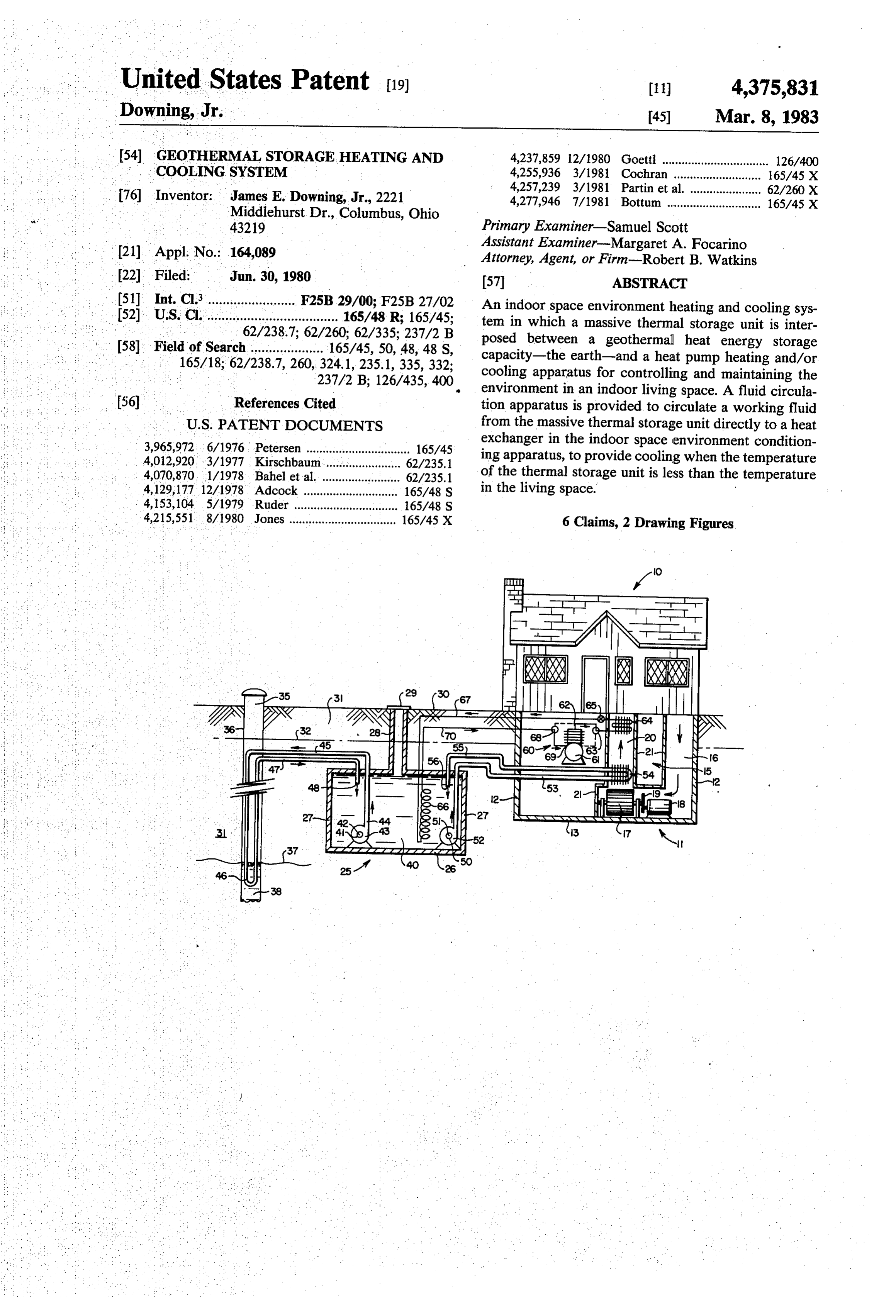
United States Patent (19) (11) 4,375,831 Downing, Jr. 45) Mar. 8, 1983 54 GEOTHERMAL STORAGE HEATING AND 4,237,859 12/1980 Goetti ................................. 126/400 COOLING SYSTEM 4,255,936 3/1981 Cochran ...... 165/45 X 76 Inventor: James E. Downing, Jr., 2221 4,257,239 3/1981 Partin et al. ...................... 62/260 X 4,277,946 7/1981 Bottum ............................. 165/45 X
Middlehurst Dr., Columbus, Ohio 43219 Primary Examiner-Samuel Scott 21) Appl. No.: 164,089 Assistant Examiner-Margaret A. Focarino Attorney, Agent, or Firm-Robert B. Watkins 22 Filed: Jun. 30, 1980 57 ABSTRACT (51) Int. Cl......................... F25B 29/00; F25B 27/02 An indoor space environment heating and cooling sys 52) U.S. C. .... -P- - - - O -O- 165/48 R; 165/45;
tem in which a massive thermal storage unit is inter
(58) Field of Search..................... 165/45, 50, 48, 48 S,
posed between a geothermal heat energy storage capacity-the earth-and a heat pump heating and/or cooling apparatus for controlling and maintaining the 237/2 B; 126/435,400. environment in an indoor living space. A fluid circula
References Cited tion apparatus is provided to circulate a working fluid
3,965,972.6/1976 Petersen ................................ 165/45 exchanger in the indoor space environment condition 4,012,920, 3/1977 Kirschbaum....................... 62/235.1 ing apparatus, to provide cooling when the temperature 4,070,870 1/1978, Bahel et al. ........................ 62/235.1 of the thermal storage unit is less than the temperature 4,129, 17712/1978 Adcock ..... ... 165/48 S in the living space.
4,153,104 5/1979 Ruder .... ... 65/48 S 4,215,551 8/1980 Jones ................................. 165/45 X 6 Claims, 2 Drawing Figures
Page 2
Drawing sheet — no readable text.
Page 3
In addition, a working fluid, such as water, is circu
GEOTHERMAL STORAGE HEATING AND lated between heat exchangers, one of which is located COOLING SYSTEM in the massive thermal storage unit in contact with the working fluid therein and the second of which is lo
SUMMARY OF THE INVENTION 5 cated in the indoor living space environment. More specifically, in a preferred embodiment of the
This invention relates to a geothermal storage system for heating and cooling the environment of indoor liv invention, water is circulated in a closed circuit be sing space. More particularly, it relates to such a system tween a well which projects below the water table of in which a massive thermal storage unit is interposed the earth and a large water storage tank adjacent to a between a geothermal storage capacity of substantially 10 building containing the living space that is to be heated infinite size-the earth-and mechanical heat exchange waterand cooled to provide year round comfort. A second apparatus in contact with the living space. circulating system circulates water by pumping With the increased demand for energy throughout means through a heat exchanger within the large water storage tank and a heat exchanger in a forced air space the world and the consequent increase in value and cost conditioning heating and cooling apparatus of the build has come a change in the perception of value of alter- 15 ing. In addition, nate sources of energy. Sources of energy which were a heat pump means, having a working fluid such as Freon, compresses and circulates the considered too expensive or too dear in prior times are working now becoming appropriate sources as other sources evaporation fluid from an oversized evaporator in which an such scarce.
as fossil '''fuel become more expensive and more 20 tank throughcoil is submerged in the large water storage a condenser in the forced air space condi . . It has long been known that the earth's temperature tioning system of the building by means of a compressor and expansion valve within the heat pump apparatus remains substantially constant at levels below the frost means. The evaporator is sized so that even though line and within several hundred feet of the surface of the refrigeration occurs, the temperature decrease is mini earth. Nevertheless, this area has not universally been 25 mal so that the highly advantageous temperature of 45 thought of as a source of energy and the term geother F. (6.85° C) is maintained.
mal has been more universally applied to those unusual An important feature of the present invention is the occurrences of nature when hot fluids such as water and closed circuit circulatory system between the geother gas occur in pockets beneath the earth and have been mal storage capacity-the earth-and the massive ther tapped for their heat content. The conceptual model of 30 mal storage unit-the water tank. In this system the an energy "source' involves entirely different behav working fluid, water, circulates through the area of the tioral characteristics from energy "storage' capacity. geothermal storage capacity in a closed circulating For the purposes of this invention, the earth below loop. Heat exchange
I the surface shall be considered a geothermal storage circulating working contact between the earth and the unit of such large capacity to be uneffected by the rate passing the closed end loop preferably fluid is maintained by of heating and cooling required for maintaining the through a water well which has been excavatedsystem " . . . . ... . . . . . .. .. . . 35 of the circulating
environment of contiguous living space at normal depth well below the water table and through which human comfort levels day in, day out, year round, in all subterranean water is constantly moving. Because the but the most severe climates of the world. That is to say, system is a closed that the vastness of the earth in the area near the surface 40 turbed in its flowloop, the subterranean water is undis of a depth of several hundred feet is a geothermal reser stant in flow and undepleted by theandaction and quantity, is therefore, con of the system.
voir of sufficient capacity to store the amount of heat Another important feature of the invention is the necessary to maintain adjacent contiguous living space relatively massive size of the thermal storage unit which in the range of 70 F. in the coldest winter weather for is interposed between the earth and the heat exchange periods exceeding the maximum recorded cold 45 apparatus. Since the thermal storage unit is the center of weather. Likewise, this vast geothermal storage unit has a closed system, the capacity to absorb the excess heat necessary to ren working fluid, norneither requiring a constant input of der living space temperate and comfortable for periods ing fluid, a relatively largeaunit having constant exhaust of work may be used and once longer than the most protracted recorded periods of hot filled, will require only an insignificant amount of make weather in all but the most extreme weather places of 50 up and further cost. Thus, it can economically be of theThe world. relatively large size and capacity, and can be capable present invention is a complete system for pro absorbing large quantities of heat and conversely pro of viding space heating and cooling, for an indoor living viding large quantities of heat in the cooling and heating space which will bring the heat from the geothermal season, respectively.
storage capacity--the earth-to the indoor living space 55 Because in many climates the amount of sunshine is during the heating season and will extract heat from the limited and less than preferred, heating and cooling indoor living space and absorb the heat into storage systems having thermal storage capacity are frequently during the cooling season. In the system, a relatively found in solar heating designs and concepts. massive thermal storage unit is interposed between the Various methods and apparatus have been proposed geothermal storage capacity-the earth-and the in in the past which use thermal storage units in conjunc door living space environment which is to be heated tion with water in the earth to provide space heating and cooled. A working fluid, such as water, is circu and cooling in buildings. These various methods and lated between the massive thermal storage unit, such as apparatus have been utilized with limited success. A a large tank for the storage of water, and the geothermal solar heating system using underground wells is shown storage capacity--the earth. Mechanical heat exchange 65 in U.S. Pat. No. 3,965,972-Peterson. A solar heating apparatus, preferably a heat pump, is operatively con system using an underground tank is shown by Corn nected between the massive thermal storage unit and wall in U.S. Pat. No. 2,533,302. A thermal storage appa living space environment. ratus in the basement of a building is shown in U.S. Pat.
Page 4
No. 3,236,294-Thomason. U.S. Pat. No. conduits 41, 45 from the tank 26 in a closed loop of 4,129, 177-Adcock shows a solar heating and cooling continuous circulation.
system in which thermal energy storage bags are used. In a second circulation subsystem of the working The above cited patents are provided in compliance fluid 40, a conduit 50 circulates working fluid 40 from with 37CFR Rule 1.56. 5 an inlet 51 to the intake of a second submersed pumping Other important features of the invention will be means 52, which discharges into an outlet conduit 53 apparent from the drawings and detailed description of through a heat exchanger 54 which is located in the the invention which follows. supply air duct 20. From the heat exchanger 54, a con
BRIEF DESCRIPTION OF THE DRAWINGS
duit 55 carries the working fluid 40 back into the tank 26
O through and outlet 56.
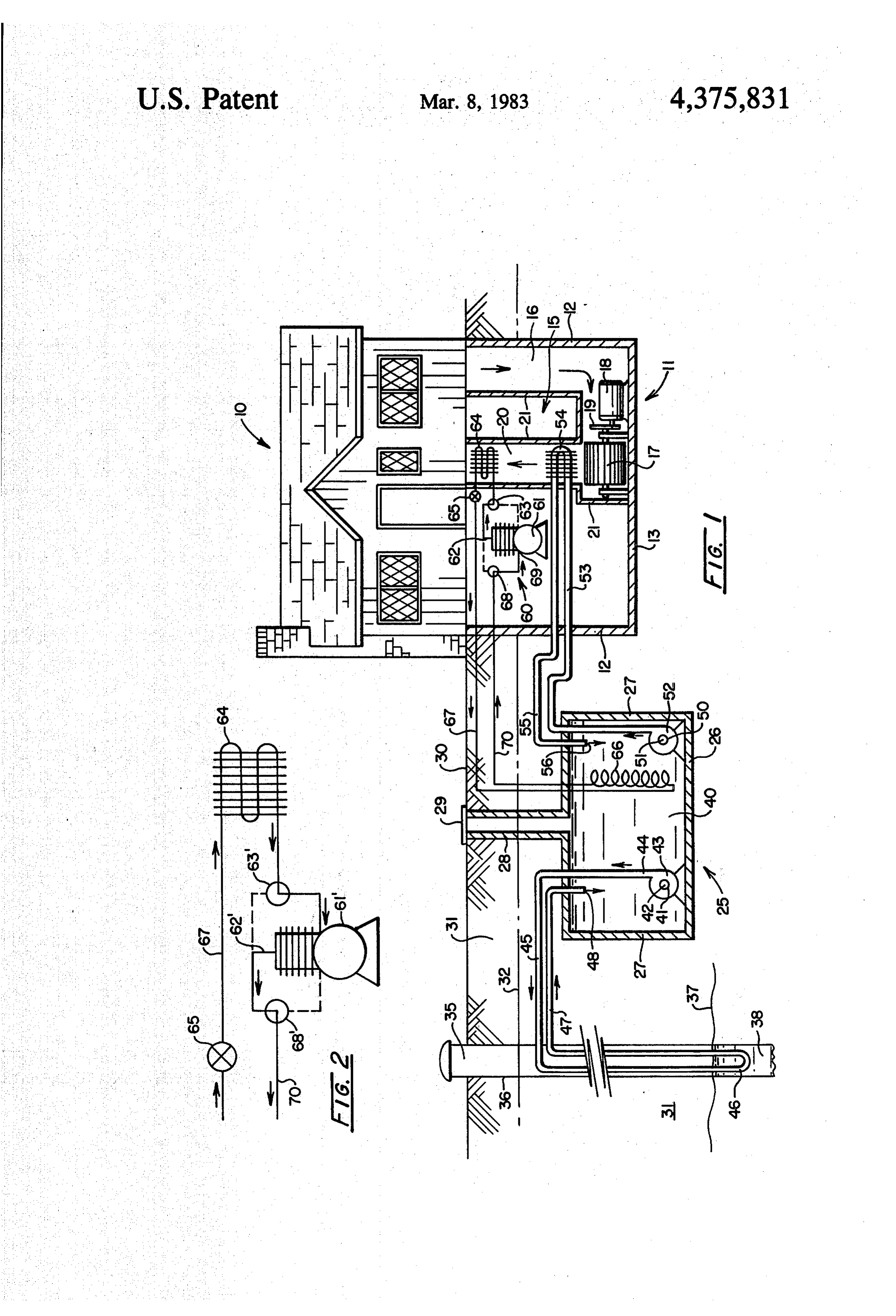
FIG. 1 is a partialavertical sectional view of a dwell The massive thermal storage unit 25 of this invention ing house having indoor living space environment heat in combination with the thermal storage capacity of the ing and cooling requirements, and the principle ele earth 31 makes possible the use of the greatly simplified ments of the heating and cooling system of the inven 15 cooling subsystem using the pump means 52. With the tion. working fluid 40 at a substantially constant temperature FIG. 2 is a schematic diagram of a portion of the of 45 F. (6.85 C.) during the cooling season, substan apparatus of this invention shown in a different operat tial cooling for the living space can be provided at the ing mode from that shown in FIG. 1. heat exchanger 54 by the circulation of the working fluid 40 directly between the thermal storage unit and
DETAILED DESCRIPTION OF THE 20 the heat exchanger.
INVENTION A typical average cooling load of 36,000 (1.91 K Cal/sec.) BTU per hour can be absorbed by water cir
Referring to FIG. 1, a dwelling house structure 10 is culating shown above a basement 11 having walls 12 and a floor from the storage tank through the heat ex 13. Space heating and cooling apparatus 15 is shown in changer at the rate of 15 (0.001 M3 per sec.) gallons per the basement 11 including a circulating/incoming (re 25 minute.
The temperature of the water 40 in the tank 26 can be turn) air duct 16, a circulating fan/blower 17 driven by maintained at substantially a 45 F. (6.85 C.) tempera a motor means 18 with belts 19 and an outgoing (supply) ture by circulation air duct 20. as necessary through the well 35 by The detailed construction of the space heating and 30 As shown in FIG.means operation of pump
the pump means 43, 52 are lo cooling apparatus is in general conventional having, cated within the thermal storage typically, a plurality of sheet metal sides 21 connected Alternatively, these pumps couldtank be 26 (submerged).
located in other to registers (not shown) in the walls and floors of the places such as in the basement 11 of the dwelling house dwelling house structure 10. 10, or on the surface 28 outside the house. A massive thermal storage unit means 25 includes, 35 Referring again to FIG. 1, heat pump apparatus preferably, a water storage tank 26 having ends 27, and means 60 includes a compressor 61 for a refrigerant gas, access conduit 28 and a lid 29. Thermal storage unit 25 such as Freon. Heat pump means 60 is connected is placed beneath the surface 30 of the ground 31 below through a compressed gas outlet 62, and a reversing the frost line 32. Preferably it is constructed of thick valve 63 to a heat exchanger 64 in the supply air duct concrete which is relatively inexpensive; and being 20. The heat exchanger 64 is connected to an expansion dense it adds to the thermal storage of the unit. valve 65, which is in turn, connected to an evaporator/- However, the thermal storage unit 25 may be of steel heat exchanger 66 through expander conduit 67. The or concrete construction materials depending on local evaporator/heat exchanger 66 is connected through a factors such as terrain, composition of the earth and second reversing valve 68 to an inlet 69 of the compres economic considerations. 45 sor 61 by means of a conduit 70. The pressure within the tank 26 is substantially atmo As shown in the embodiment of FIG. 1, the heat spheric; and therefore pressure vessel type construction pump means 60 is set by means of the reversing valves is not required. 63 and 68 in the heating mode of operation. In this A working fluid 40, preferably water, is introduced mode, Freon gas is compressed in the compressor 61 to into and fills the tank 26 to a maximum desired level 50 a pressure of about 250 lbs. per sq. in. (0.065 Kg/M2) depending on operating criteria and economical consid and a temperature of approximately 180° F. (78 C.) At erations of the locality. this temperature, it passes through the heat exchanger A well 35 having a casing 36, is established down into 64 giving up heat to circulating air forced upward the earth 31 to a depth below the water table 37. Subter through the supply air duct 20 by the blower 17. The ranean water 38 fills the well 35 to the water table 37. 55 cooled gas is expanded in the valve 65, passes into the A closed circuit circulation subsystem for the work liquid state, and flows into the evaporator/heat ex ing fluid 40 is provided, including as shown in FIG. 1, changer 66 in a chilled state at a temperature of about a conduit/piping 41 passing from an inlet 42 below the 35 F. (1.7° C) In the evaporator/heat exchanger 66, surface of the fluid 40 to the inlet of a submersed pump the Freon absorbs heat from the working fluid 40 and means 43 through an outlet 44 into an outlet piping 60 evaporates to a gaseous state passing through conduit /conduit 45. The outlet piping conduit 45 continues 70, valve 68 and into the compressor 61 at inlet 69. beneath the frost line 32 into the well 35 through casing The operation of the heat pump apparatus of the type 36 where a heat exchange loop 46 passes through the used in this invention is well known, although success subterranean water 38 beneath the water table 37, and ful operation depends on the successful control of vari through a return conduit 45 to an outlet 48 in the tank 65 ous variables. A very important variable is the tempera 26 of working fluid 40. ture of the working fluid in outside contact with the Operation of the pump means 43 circulates the work evaporator during the heating mode. Because water, as ing fluid 40 in the direction of the arrows through the a working fluid, is more expansive than ambient air,
Page 5
... " 5. 6 many heat pumps,have been operated with ambient air In some locations the water table is very low and it as the working fluid at the evaporator. Also in the past, may not be economical or possible to connect the mas because electrical energy, was relatively...inexpensive, sive, thermal storage unit to... the geothermal storage heat pump compressors were designed to operate long capacity of the earth by means of a well. In such a and hard to extract heat from ambient air which was at situation, a circulation subsystem from the thermal stor a very low temperature during the heating season. In age unit. through subterranean ground coils buried addition to the amount of work necessary to extract below the frost level can be used to provide the geo heat from low temperature, air, there was often the thermal storage capacity. The ground coils would then problem of moisture freezing in the air contacting the be larger piping and more than extensive tubing into a evaporator. . . .. .. . . . . 10 well.
With the increased cost in electrical energy, more In some circumstances in order to further reduce heat pump installations have been designed for water as the working fluid across the evaporator in recent years. electrical not be an energy requirements and where first cost may important criterion, a circulation subsystem
The water may be from any source, but usually water between heating panels on the roof of the dwelling from a central system in an urban area is found to be too house and the thermal
storage unit could be provided. If expensive as a working fluid. Natural water from wells in the vicinity of the heat pump have been used success this were done, the temperature and heat in storage in fully in reducing electrical energy costs in the operation the thermal storage unit would be raised during the of heat pumps. These systems are not entirely satisfac heating season to further increase the efficiency of the tory since prolonged low temperature heating seasons 20 heat In pump operation.
some climates, under certain rare conditions, it require large quantities of water if the evaporator dis may be necessary on occasion to provide additional charge is being wasted. Also, if the water discharge is being returned to the water well the temperature of the cooling for the living space of the dwelling 10. This is accomplished as necessary by reversing the heat pump : water in the well is reduced which decreases the tem perature of the heat pump evaporator when it is recircu 25. 60,Referring as shown in FIG. 2.
to FIG. 2, the refrigerant compressor 61 is lated.
connected from an outlet 62 and reversing valve 68 to . . In the operation of the system of this invention, the heat heat pump is rendered more efficient over a protracted changer exchanger 66 through conduit 70. The heat ex period of time and the efficiency is substantially unaf. 66 is connected through conduit 67 and the fected by the outside weather and temperature condi 30 expansion valve 65 to the heat exchanger 64 in the sup tions. The system of this invention combines the rela ply air duct 20. The heat exchanger 64 is connected tively infinite heat storage capacity of the earth at sub through reversing valve 63 to the compressor 61. stantially constant temperature, about 45 F., (6.85 C.), In operation, refrigerant gas is compressed in the with a relatively massive thermal storage unit located compressor 61, to a temperature of about 180' F. (78" conveniently near the heat pump means and the indoor 35 C.) and a pressure of about 250 lbs. per square inch living space cooling means. (0.065 Kg/M2). In heat exchanger 66 it is cooled giving Assuming a home heating consumption rate of up heat to the working fluid 40. 1,000,000 BTU's (50KC) per day, which would be quite A heat pump set in the heating mode in combination high but could be the consumption that would be re with a massive thermal storage unit as shown in FIG. 1, quired several times during a winter, a 1500 gallon (6000 can also be connected in heat exchange relationship Liter) water tank is an adequate massive thermal stor with a hot water heating tank. Because the heat pump age unit for the heating mode of the system of this in has a constant inexpensive source of working fluid at vention. The average furnace produces 100,000 BTU’s 45 F. (5.68 C.) at the evaporator, it will provide suffi (5 KC) per hour and would run 10 hours to produce cient heat to the water for many purposes. 1,000,000 BTU's (50 KC). 45 It is herein understood that although the present in Working fluid water comes from the well at about 45° vention has been specifically disclosed with preferred F. (6.85 C.) In the typical closed circulation system of embodiments and examples, modifications and varia this invention, water 40 is circulated at the rate of ap tions of the concept herein disclosed, may be resorted to proximately 20 gallons per minute by the electric motor by those skilled in the art. Such modifications and varia driven pump 43 through three quarter inch plastic tub 50 tions are considered to be within the scope of the inven ing between the well 35 and the thermal storage tank 26. tion and the appended claims.
In constant operation during each day, 28,800 gallons What is claimed is:
(109,440 Liters) of water would flow through the well 1. A geothermal system for heating and cooling the in the closed loop circulation system. Considering a environment of indoor living space, comprising: temperature change of 4 F. (1 C) higher as it passes 55 . (a) a massive thermal storage means; through the well 921,200 BUT's (46.06 KC) would (b) a geothermal storage capacity means connected to move from the well into the thermal storage unit per the massive thermal storage means in a heat trans day. fer relationship by a first subsystem comprising a The temperature of the water in the thermal storage closed circuit for conducting a working fluid be tank remains substantially constant at about 45' F. tween the massive thermal storage means and the (6.58 C.) The evaporator 66 of the heat pump 60 is in geothermal storage capacity means as induced by a contact with the working fluid 40 substantially at con first pumping means in the closed circuit, the geo stant optimum temperature. At the expansion valve 65 thermal storage capacity means being the earth; the refrigerant gas expands into the heat exchanger 64 at (c), heat pump means operably connected to a first a temperature of about 35 F. (1.7. C.) The passing 65. heat exchanger in the environment of the living warm air from the living space is cooled and dried space and operably connected to a second heat giving heat to the refrigerant gas which passes to the exchanger in the massive thermal storage means in inlet of the compressor. heat exchange contact with the working fluid; and
Page 6
(d) a second subsystem comprising a closed circuit for 4. A geothermal system according to claim 1 wherein conducting the working fluid between the massive the geothermal storage means is the earth and the closed thermal storage means and a third heat exchanger circuit of the first subsystem passes through a well of in the environment of the living space connected in 5 subterranean water from the earth. . heat exchange contact with the working fluid. 5. A geothermal system according to claim 1 wherein the thermal storage means has access to atmospheric 2. A geothermal system according to claim 1 wherein pressure. . .
the massive thermal storage means is a tank and the 6. A geothermal system according to claim 1 wherein working fluid is a liquid. the first heat exchanger and the third heat exchanger 3. A geothermal system according to claim 1 wherein O are placed in the air supply duct of a forced air space the massive thermal storage means is a tank containing heating and cooling apparatus.
Water. "
Provenance
- Collection
- Cited prior art
- Original PDF
- patentimages.storage.googleapis.com →
- Filed
- 1980-06-30
- Pages
- 6
- Method
- pdftotext (the PDF's own text layer) + pdftoppm 300dpi page scans
- Source
- Google Patents bibliographic record
- Granted
- 1983-03-08
- Inventors
- James E. Downing, Jr.
- Transcribed from
- patentimages.storage.googleapis.com →