patent · US4142576
Heat pump system with improved heat transfer
6 March 1979
Page 1 — bibliographic record
United States Patent 19 (11) 4,142,576 Perry et al. 45) Mar. 6, 1979
54 HEAT PUMP SYSTEM WITH IMPROVED
HEAT TRANSFER
4,011,736 3/1977 Harrison ................................ 65/45
Inventors: Elijah R. Perry, Portola Valley; FOREIGN PATENT DOCUMENTS
Mario Rabinowitz, Menlo Park, both 59350 2/1912 Switzerland ................................. 65/45 of Calif.
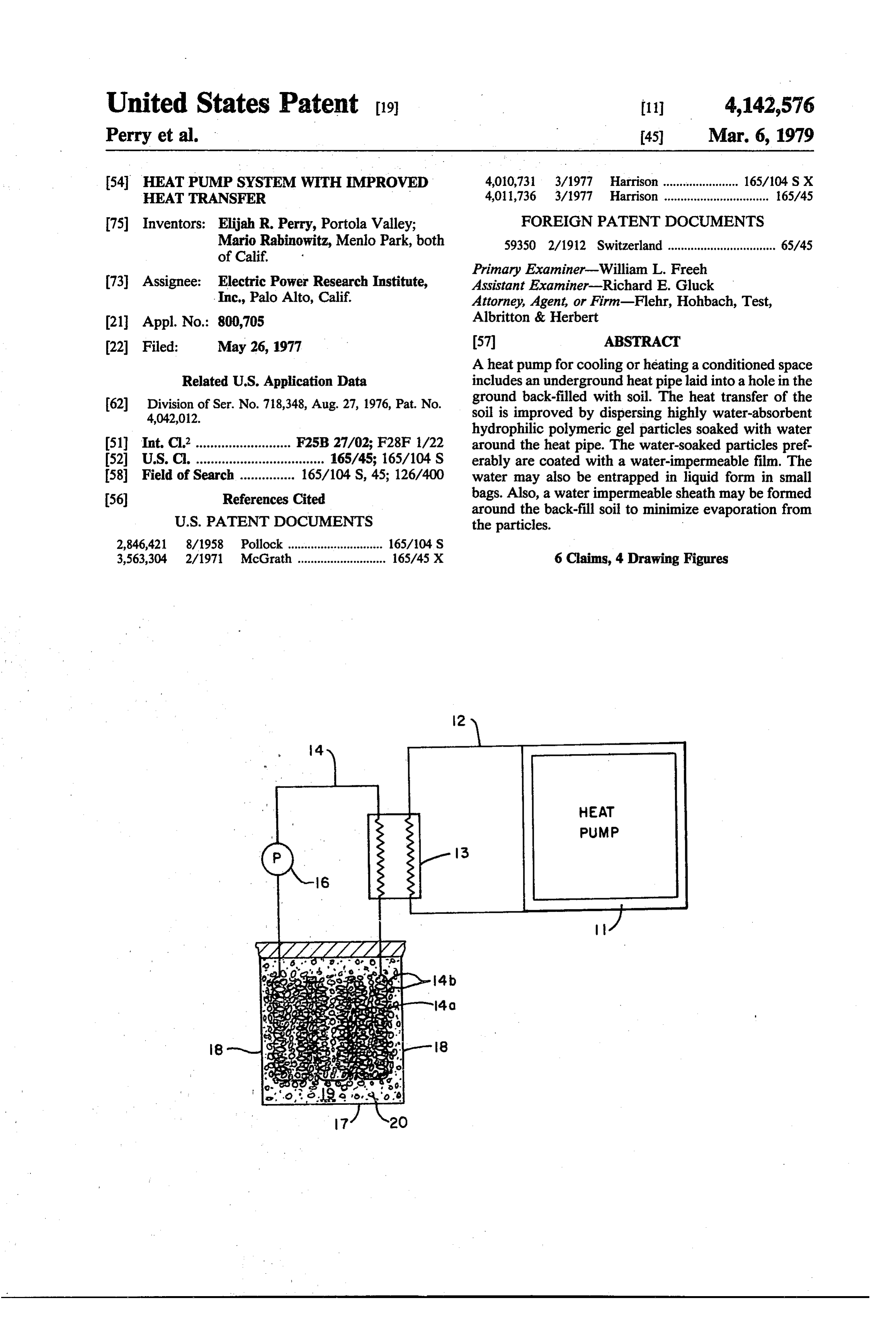
Primary Examiner-William L. Freeh 73 Assignee: Electric Power Research Institute, Assistant Examiner-Richard E. Gluck Inc., Palo Alto, Calif. Attorney, Agent, or Firm-Flehr, Hohbach, Test, 21 Appl. No.: 800,705 Albritton & Herbert 22 Filed: May 26, 1977 57 ABSTRACT A heat pump for cooling or heating a conditioned space
Related U.S. Application Data includes an underground heat pipelaid into a hole in the 62) Division of Ser. No. 718,348, Aug. 27, 1976, Pat. No. ground back-filled with soil. The heat transfer of the 4,042,012. soil is improved by dispersing highly water-absorbent hydrophilic polymeric gel particles soaked with water (51) Int. Cl’.......................... F25B 27/02; F28F 1/22 around the heat pipe. The water-soaked particles pref (52) U.S. C. ................................... 165/45; 165/104 S erably are coated with a water-impermeable film. The 58 Field of Search ............... 165/104 S, 45; 126/400 water may also be entrapped in liquid form in small (56) References Cited bags. Also, a water impermeable sheath may be formed
around the back-fill soil to minimize evaporation from the particles.
2,846,421 8/1958 Pollock ............................. 165/104 S 3,563,304 2/1971 McGrath ........................... 165/45 X 6 Claims, 4 Drawing Figures
Page 2
Drawing sheet — no readable text.
Page 3
efficiency of heat transfer with the liquid in the heat
HEAT PUMP SYSTEM WITH IMPROVED HEAT pipe correspondingly decreases. This is a particular
TRANSFER problem during the summer months in which the mois
This is a division of application Ser. No. 718,348 filed ture content decreases to a minimum, due, in large part, Aug. 27, 1976, now U.S. Pat. No. 4,042,012. 5 to the heating of the soil by solar energy during the
CROSS-REFERENCE TO RELATED
longer daytime periods.
APPLICATION Recently, various hydrophilic polymeric gel sub stances have been developed with extremely high water
Reference is made to Perry etal application, Ser. No. holding capacities. One such product is described in an 718,349, filed Aug. 27, 1976, now U.S. Pat. No. 10 article entitled "Super Slurper-Compound with a Super 4,097,682, entitled Means for Protecting Underground Thirst", Agricultural Research, June 1975 (published by Electrical Equipment from Thermal Runaway. Agricultural Research Service, USDA). It is a hydro BACKGROUND OF THE INVENTION lyzed starch polyacrylonitrile graft copolymer. One use disclosed for this material is to increase the water-hold
A heat pump raises the temperature level of heat by 15 ing capacity of sand to enhance the top growth of crops means of work input. The pump cycle is identical with such as oats. The article states that the sand, by itself, the vapor compression refrigeration system. It finds retains only 24 grams of water compared with 317 particular application for air-conditioning of an air space such as a home since it employs the same equip grams of water held by the sand-gel mixture at a con ment to cool the conditioned space in the summer and 20 gels are saidoftoone centration part of gel to 250 parts of sand. Such absorb as high as 1,000-2,000 times their to heat it in winter. This dual purpose is accomplished weight of water.
by valving which places the low temperature evapora Another type of hydrophilic gel is sold by Union tor in the conditioned space during the summer and the Carbide under the trademark “Viterra" hydrogel. This temperature condenser in the same space during the winter. In effect, such heat pumps heat (or cool) the 25 syntheticused as an material is suggested by Union Carbide to be additive to the soil to assist transfer of water interior of the buildings by refrigerating (or heating) the and nutrients to a growing plant. Product literature outdoors. The principle of this operation was first de from Union Carbide suggests that the Viterra hydrogel scribed by Kelvin in 1852.
The coefficient of performance cp for cooling a con can retain more than twenty times its dry weight of ditioned air space is given in equation (1) and the coeffi 30 water. Another such product called "Imbiber Beads' is cient cp for warming the space is given in equation (2), manufactured by the Dow Chemical Company with a wherein T is the temperature ib absolute degrees and 27:1 holding capacity.
the subscripts c and hrefer to the cold and hot tempera All these polymers have the capacity to take in a tures, respectively. large quantity of water without becoming dissolved. The water actually penetrates the polymer network , cp = refrigeration/work = T/(T-T) (1) 35 causing the size of the particle to increase, but in so , cp = heat delivered/work = T/(T-T) (2) doing, no large pockets of water are formed which might later leak out. The water is actually entrapped by
It is apparent from the foregoing equations that maxi the molecular structure of the polymer. It is extremely mum performance is obtained when the temperature 40 difficult mer.
to squeeze out entrapped water from the poly
However, water can be evaporated from the poly differential between the outside temperature and that of mers, and the starch-based copolymer is biodegradable. the conditioned space is a minimum.
The most common source of exterior heating or cool ing is the surrounding air because of its convenience. Summary of the Invention and Objects However, since the air heats to relatively high tempera 45 tures in the summer and cold temperatures in the win transfer In accordance with the present invention, the heat ter, it is the least efficient source of cooling and heating. source orofsink a heat pump using the ground as a heat is improved by surrounding the under
Furthermore, in most temperate zones, the heating load ground heat pipe with soil containing a plurality of is usually greater than the cooling load. This leads to an water-soaked absorbent particles to provide a jacket of imbalance in the sizing of equipment and necessitates a high thermal conductivity.
A preferred form of absor large, high horsepower compressor fitted to the heat bent particles is a hydrophilic polymeric gel material. demand, a supplementary heating system (electrical resistance or fuel), or a heat-storage system. To minimize loss of water from the particles, after soak The use of well water as a heat source is more effi ing with water, they may be coated with a water cient than atmospheric air. However, the impurity, 55 impermeable film and then mixed with the soil. In an quality, quantity ad disposal of water and the corrosion alternative embodiment, the particles are formed of problems of the pipe and the water have minimized the flexible balloon-like bags filled with water without an use of such systems. absorbent core. Other ways to prevent loss of water Another heat source is the use of the earth itself by from the soil surrounding the heat pipes include laying laying a heat pipe of the heat pump in an underground 60 a water-impermeable film above the pipes, or com hole and then backfilling it with soil. The earth is poten pletely surrounding them.
tially the most desirable heat source or sink because of andIt means is an object of the invention to provide a method for improving the heat transfer to the under its availability and seasonal uniformity of temperature.
However, heat transfer between the liquid in the heat ground heat pipe of a heat pump.
pipe and the soil depends largely upon the moisture 65 It is a particular object of the invention to accomplish content which is related to climate conditions and geo the foregoing object by including highly absorbent logical formation. That is, as the moisture content de particles soaked with water or water-filled, balloon-like creases, the thermal conductivity of the soil and thus the bags in the soil back-fill.
Page 4
It is another object of the invention to retain the additive may be added to prevent freezing, if necessary. water in the soaked absorbent particles in the soil back Brine is a suitable inexpensive heat exchange fluid for fill by coating them with a film of water-impermeable line 14 in a cold climate.
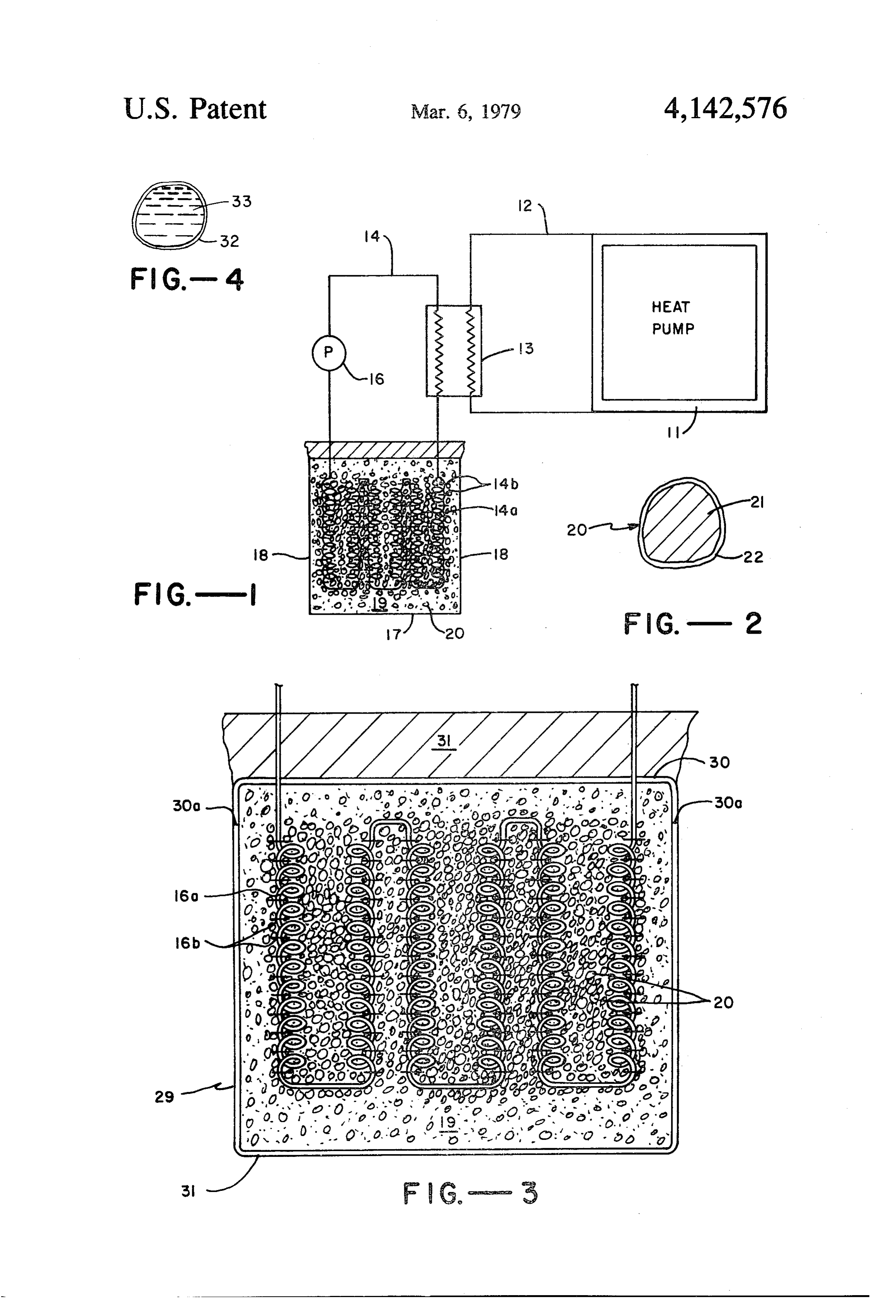
film. Referring again to FIG. 1, a hole is dug having a It is an additional object of the invention to provide a 5 bottom wall 17 and upwardly extending side walls 18. roof to prevent evaporation from the water absorbent Then, pipe 14 is laid into the hole and the soil removed particles. during digging of the hole is used to bury or back-fill It is another object of the invention to provide means the heat pipe. In accordance with one embodiment of for preventing water from seeping out of the soil from the present invention, the back-fill soil 19 surrounding below and to the sides of the heat pipes. O pipe 14 contains water-soaked absorbent particles 20 in Further objects and features of the invention will be random dispersion. The absorbent particles 20 may be apparent from the following description in which the mixed during back-filling as with a hose system. preferred embodiments are set forth in conjunction with Referring to FIG. 2, in a preferred embodiment, par the appended drawings. ticles 20 include a central core 21 formed of water 15 impermeable material. In certain environments where
BRIEF DESCRIPTION OF THE DRAWINGS
water loss from the soil is not excessive, it should be
FIG. 1 is a schematic block diagram of a heat pump understood that particles 20 may comprise core 21 only with an underground heat pipe in contact with under without any film coating. The last-named embodiment ground soil having improved heat transfer characteris will be first described in detail.
tics in accordance with the present invention. 20 The purpose of adding the water-soaked particles to FIG. 2 is an expanded cross-sectional view of coated the back-fill surrounding heat pipe 14 is to maintain a absorbent particles for use in the back-fill soil of FIG. 1. higher water content in the soil throughout the year, FIG. 3 is a cross-sectional view of another embodi especially during the hot, dry summer months. Such ment of the heat pipe and underground soil combination Water content greatly increases the thermal conductiv of the present invention. 25 ity and also thermal capacity of dry soil. Therefore, heat FIG. 4 is an expanded cross-sectional view of water is readily transferred between heat pipe 14 and the moist filled bags for use in the back-fill soil of FIG. 1. ground. This is accomplished not only by increasing the DETAILED DESCRIPTION OF THE thermal conductivity surrounding the heat pipe, but PREFERRED EMBODIMENTS also by increasing the effective interface between the 30 heat pipe system and the remainder of the earth.
Referring to FIG. 1, a block flow diagram of a heat The timing of soaking the uncoated absorbent parti pump 11 is illustrated in which a refrigerant fluid in line cles 20 with water may be varied to suit the conve 12 is circulated through a heat exchanger 13. The heat nience of the crew laying the heat pipe 14. Thus, the pump may be of any conventional type employed for particles may be soaked prior to dispersion in the back cooling or heating a conditioned air space such as a 35 fill soil, or during or subsequent to back-filling as by room in a commercial or residential building. A major pouring water into the trench at such times. advantage of such heat pumps is that they employ the The absorbent material of particles 20 has a high same equipment for cooling in summer or heating in capacity for water so that it can retain a maximum winter by appropriate shifting of valve settings to re water content in hot summer months. For example, the verse the flow of refrigerant. A typical heat pump in 40 absorbent preferably is characterized by a water capac cludes a motor operated compresser, a condenser, a ity of at least 10-20 times its dry weight. It is preferably liquid receiver, an expansion valve and an evaporator. in the form of a hydrophilic water-swellable, insoluble, Any suitable refrigerant may be employed in line 12 cross-linked polymeric gel material.
such as a variety of chlorofluoromethane materials sold If the particles are not protected by coating 22 they under the trademark "Freon.' A detailed construction 45 should be sufficiently inert to the soil environment and and operation of conventional heat pumps are set forth be non-biodegradable to withstand long-term retention in the following books: Sporn et al, Heat Pumps, (Wyley in the soil. Suitable inert absorbent materials of this type & Sons, 1947); and Kemler et al, Heat Pump Applica include cross-linked synthetic polymers. One type is tions, (McGraw-Hill, 1950). manufactured by Union Carbide Corporation under the Referring again to FIG. 1, heat is supplied in under 50 trademark "Viterra' hydrogel. This material is a non ground heat pipe 14 for transfer to the refrigerant in line ionic polymer which is highly stable over long periods 12 by heat exchanger 13. The liquid in pipe 14 flows in of time, even in high temperatures, is non-biodegradable a closed loop under pressure supplied by pump 16. In and is essentially inert to acids. It is stated to have a the illustrated embodiment, the underground portion of water capacity of about 20-25 times its dry weight. pipe 14 includes a maximum surface area for heat trans 55 Another type is manufactured by Dow Chemical Cor fer with the soil. Thus, the underground portion of of poration under the name "Gel-Guard” and "Aqua pipe 14 includes coils 14a and fins 14b. In addition, the Biber.” These materials are stated to be quite stable, pipe is arranged in a serpentine path as illustrated to non-biodegradable, and not vulnerable to acids. further maximize the heat transfer area. It is preferable A number of other solid water-insoluble sorbents that to form the pipe of a material of high thermal conduc Swell in water are described in a paper by Weaver et al tivity such as copper. For economy of hole space, it entitled "Highly Absorbent Starch-Based Polymer,” may be desirable to employ a plurality of underground presented at the International Nonwovens & Disposa heat pipes connected through a manifold to the main bles Association, Washington, D.C. Mar. 5-6, 1974. line which passes through heat exchanger 13. One such product is a base-hydrolyzed starch-polya The heat exchange liquid in heat pipe 14 should have 65 cryionitrile graft copolymer in which the nitrile func good heat transfer properties and not freeze at the cold tionality has been converted to a mixture of carboxya est temperature in the climate of use. Thus, water may mide and alkali metal carboxylate. The paper states that be employed in warmer climates while an anti-freeze after drying to the carboxylate form, this material is
Page 5
capable of imbibing about 700 times its own weight of ter. Thus, all of the water initially present in the soaked deionzed water. core 21 would be retained in the back-fill soil. Of A particular absorbent of the general type described course, cracks in the coating may develop during abra in the Weaver et al paper is manufactured by General sion or under the pressure of the back-fill soil. How Mills Chemicals, Inc., under the designation “SGP 5 ever, even in these instances, the great majority of the 502S,' commonly referred to as "Super Slurper.” This core material is protected from exposure to evapora product is stated to have a typical water-holding capac tion, thereby increasing the life of water retention to a ity of 800-1,000 ml. of deionized water or 350-450 ml. major extent.
of Minneapolis tap water per gram of product. One Another advantage of such coating is to protect the problem with this material is that the application of high O absorbent particle core from biological components of pressure disrupts the gel structure to release absorbed the soil. Thus, such a coating can protect a biodegrad fluid. Also, water-swollen dispersions of this product able starch-based absorbent core of the foregoing type. are stated to be susceptible to bacterial attack and to The thickness of film 22 should be sufficient to pro deteriorate on prolonged storage at room temperature. vide strength to withstand handling and the pressures Because of their stability and non-biodegradability, 15 created during back-filling. In addition, the film should the Gel-Guard and Viterra hydrogel products are par be of sufficient thickness to prevent permeation of ticularly suited for use with a protective coating 12. water therethrough. These characteristics are depen However, they have a far lower water capacity than the dent not only upon thickness but also upon the type of less stable, starch-based products described in the Wea material employed for the film. In general, the film of a veretal paper. The high capacity starch-based products 20 thickness of 250 microns or less is believed to be suitable may be employed by coating with a protective film of for most coating materials. If the coating material is water-impermeable, non-biodegradable material as set characterized by a low thermal conductivity it is prefer forth hereinafter. able to minimize the thickness of the film to obtain It should be understood that other absorbent material maximum benefit from the high thermal conductivity of capable of high water retention also may be used in 25 the water-soaked absorbent core.
accordance with the present invention. For example, Suitable materials for forming the water impermeable although not as absorbent as polymeric gel materials, film comprises various synthetic polymers such as poly certain molecular seive materials as of the inorganic vinyl chloride, acrylic polymers, polytetrafluoroethyl zeolite type may be employed as the absorbent material ene, or monoolefins such as polyethylene or polypro for possible special soil applications. Such materials 30 pylene. Other materials such as paints or shellacs in may be formed capable of binding water tightly. The cluding metals or other inorganic fillers may also be theory of such molecular seives is briefly disclosed at employed.
columns 3-5 of Rabinowitz U.S. Pat. No. 3,612,939. In another form, coating 22 may be in laminate form In the embodiment of FIG. 2, absorbent particles 20 and comprising two or more layers as where a single are formed of a suitable size for random dispersion 35 layer may not possess all of the desired properties. For throughout the back-fill soil. It is preferable to use large example, an inner hydrophilic polymer, such as polyvi particles to minimize the surface to volume ratio, and nyl acetate or a polyester, is readily coated as a film thus, the surface available for evaporation. By premix onto soaked absorbent core 21. However, it may not ing soil with relatively large particles (e.g., 10 cm effec possess sufficient impermeability to prevent substantial tive diameters or more) the soil fills any void spaces evaporation of water from core 21 and may not be of a created between the large particles. This minimizes character to adequately protect the core from harmful such void pockets of extremely low thermal conductiv elements in the soil. Thus, a second film sufficiently ity. Such voids may also be filled by using some smaller impermeable to protect the core and prevent evapora particles 20 together with the larger ones. To minimize tion such as poly vinylidene chloride may be coated evaporation and also permit uniform dispersion, it is 45 readily onto the first layer but not onto the core di believed that a gradation of particle sizes would be most rectly.
effective, say, with effective diameters as small as 0.5 In a further embodiment, instead of forming a lami cm. to as large as 10 cm., or larger. The precise sizing is nate to combine layers of different properties in coating not critical and will depend upon the type and depth of 22, a single coating may be applied with modified sur soil. A suitable soil includes at least 20% of the particles 50 face characteristics. For example, the surface of a poly with a diameter of at least 0.5 cm. styrene film coating, which is hydrophobic, may be Since the object of the invention is to increase the rendered hydrophilic or grafting a hydrophilic mono thermal conductivity and capacity of the soil by increas mer onto its surface such as a polyalkyl alcohol or ing its water content, it is apparent that the absorbent polyhydroxyethyl methacrylate (HEMA). Known materials of the present invention should be soaked with 55 grafting techniques may be employed such as oxidation sufficient quantities of water and for a sufficient time to of the film surface to create free radical sites. essentially saturate the absorbent materials. In this man One suitable coating material would be a hydrophilic ner, the thermal conductivity and capacity of the soil is polymer which maintains its structural integrity in the maximized for a given quantity of added absorbent form of a film even in the presence of water. Such a particles. 60 material could be sprayed with an appropriate carrier Referring to FIG. 2, a preferred embodiment of ab and permitted to dry on and be bonded to the surface of sorbent particles 2) is illustrated in which the absorbent the particles. Suitable hydrophilic polymers include water-soaked core 2 is coated with a thin film 22 of certain acrylic resins and, under certain circumstances, material which is essentially impermeable to water and polyvinyl alcohol.
non-biodegradable in the soil. 65 Hydrophobic polymeric materials may also be em A major advantage of film 22 is to prevent evapora ployed for the film by use of known techniques. For tion of water from the water-soaked core maierial. In an example, core 21 could be passed through a thin, wet ideal system, the coating is totally impermeable to wa polymer film, say, formed of a solution of polyethylene.
Page 6
Upon piercing of the film by core 21, a portion of the absorbent particles 20. Then, roof 30 is placed over the film wraps around the particles and seals against itself. upper surface of the back-fill soil and sealed with bot Then the solvent is permitted to dry. Such hydrophobic tom sheet 31. Finally, the remainder of the back-fill coating would not be bonded to the absorbent core. without absorbent is placed over roof 30. In another technique, the absorbent soaked particles 5 Referring again to FIG.3, the soaked absorbent parti could be placed in very thin open containers of dry cles. 20 are illustrated as being distributed in a concen polymeric materials which are then sealed. For exam tric, compacted layer surrounding the coil in heat trans ple, the particles may be placed into flexible bags fol fer pipe 14a. Thus, pipe 14a is totally surrounded by a lowed by heat sealing of the bag opening. Also, the layer which includes a major portion of, and preferably absorbent particles may be placed in rigid containers O consists essentially of, particles 20. formed, say, of two hemispheres of a thermo plastic A suitable sequence to accomplish the specific back polymer, e.g., polystyrene. Then, the hemispheres are fill layering of FIG. 3 is as follows. First, the hole is dug sealed as by the application of heat. and, optionally, partially back-filled with soil contain The techniques of spraying a film of shellac, varnish ing some absorbent particles. Then, pipe 14a is laid and or paint onto a surface are well known. For example, 15 surrounded with a layer exclusively containing absor spray cans are available including propellants for spray bent particles 20 including a size gradation of sufficient ing such materials in a suitable carrier onto the core for small particles to fill the voids among the larger ones. rapid drying. Soaking of the particles may be performed by previ For uniform coating with a spray, it is preferable that ously mentioned techniques and in one of the sequences the particles be rotated during spraying. One technique 20 set forth above.
for this purpose is to convey the particles to the top of The advantage of forming a layer of the preceding a spray chamber and simultaneously contact them with paragraph is illustrated by the following analysis. To the spray during gravitation of the particles. maximize heat removal from a heat source, it is impor In another embodiment, the particles could be tant to concentrate the increase in thermal conductivity sprayed on a vibratory or air bearing conveyor. In this 25 in the medium adjacent to the source and to disperse the embodiment, soaking and coating may be accomplished increase over a larger volume. Applying this principle in the same system. For example, the absorbent cores to the present invention, for a given volume of absor may pass on a conveyor through a first zone in which bent particles 20, it is preferable for a maximum increase they are soaked with water and, thereafter, through a in the heat transfer to concentrate the particles as illus second zone in which the film is applied. trated in FIG.3 rather than to disperse them through When the absorbent particles are not protected by a out the trench volume.
film 22, it may be desirable to include surfactant chemi There may be special circumstances where the soil is cals to reduce the rate of evaporation. Such surfactants preferably dispersed among absorbent particles 20. For would be most beneficial for back-fill soil subjected to example, as set forth above, such particles may be so very hot dry temperatures, such as in desert-like areas. 35 large that substantial air void space of low thermal Referring to FIG. 3, an expanded view of heat pipe conductivity would be created between particles. Pre 14 of FIG. 1 is illustrated in combination with further mixing with soil would fill the voids to some extent with means for retaining the water adjacent to coiled portion soil of better thermal conductivity than the air of void 16a of heat pipe 14. A relatively good heat transfer spaces.
sheath generally denoted by the number 29 is illustrated In an alternative embodiment, referring to FIG. 4 the serving, when disposed in the hole, to isolate back-fill water soaked absorbent core of the jacketed particles of soil 19 containing absorbent particles 20 from the sur FIG. 2 would be replaced by liquid water. In this in rounding soil. Sheath 29 may include a roof 30 with stance, bag 32 is of sufficient strength to resist rupturing downwardly projecting edges 30a meeting with a bot during the back-filling operation and afterwards. Of tom sheet 31 of a cross-section conforming to the adja 45 course, rupturing is more critical in this water embodi cent hole wall. Sheath 29 is formed of water-impermea ment than in the foregoing absorbent core one because ble, non-biodegradable material such as a metal or syn the liquid water would be free to run out of the rupture thetic polymer. The edges of roof 30 and bottom sheet whereas the absorbent would retain the water under the 31 are suitably sealed with an adhesive or, where pressure of overhead soil. A suitable jacket for bag 32 is formed of a thermoplastic material such as polyethyl a flexible balloon-like bag formed of substantially wa ene, may be sealed by the application of heat. ter-impermeable polymeric material. Thus, the water 33 A major cause of loss of water is upward evaporation. could be filled into polyethylene bags of the foregoing Accordingly, roof 30 may be employed without bottom preferred size ranges which are then heat-sealed. It is sheet 31, if desired. Alternatively, roof 30 may be omit important to avoid substantial air bubbles during filling ted leaving bottom sheet 31 to prevent water removal 55 which would reduce the thermal conductivity of the below and to the sides of heat pipe portion 14a. particles.
It is preferable that sheath 29 be formed of a material What is claimed is:
which does not interfere with heat transfer to the sur 1. In a heat pump structure for cooling or heating a rounding soil. For efficiency of operation, it is prefera conditioned air space, ble for this material to be a good heat conductor such as 60 (a) a heat exchange zone, metal. However, if this is impractical due to costs, syn (b) a refrigerant fluid line extending through said heat thetic polymeric materials may also be employed so exchange zone, long as they are not of excessive thickness so as to inter (c) an underground heat pipe extending through said fere with good heat transfer with the adjacent soil. heat exchange zone, and including a heat conduc Sheath 29 is suitably formed by the following steps. 65 tive portion, the underground portion of said pipe After the hole is dug, bottom sheet 31 is laid to conform being continuous, to the hole walls. Then pipe 14a is laid to the interior of (d) back-fill soil around said underground pipe heat the sheath together with back-fill soil containing soaked conductive portion, and
Page 7
(e) a plurality of water-filled bags dispersed in said 4. The structure of claim 1 in which said bags form a back-fill soil. concentrated layer about said heat pipe. 2. The structure of claim 1 together with an imperme 5. The structure of claim 3 in which said bags are able roof dispersed over the upper surface of the back present in a gradation of sizes sufficient for void spaces fill soil and heat pipe. among the larger particles to be filled to a sufficient 3. The structure of claim 1 together with an imperme extent with the smaller particles. able lower sheet with upwardly extending side walls 6. The structure of claim 1 in which the walls of the and a bottom disposed below and to the sides of said water-filled bags areis flexible.
heat pipe. O
Provenance
- Collection
- Cited prior art
- Original PDF
- patentimages.storage.googleapis.com →
- Filed
- 1977-05-26
- Pages
- 7
- Method
- pdftotext (the PDF's own text layer) + pdftoppm 300dpi page scans
- Source
- Google Patents bibliographic record
- Granted
- 1979-03-06
- Inventors
- Elijah R. Perry; Mario Rabinowitz; Electric Power Research Institute Inc
- Transcribed from
- patentimages.storage.googleapis.com →