patent · US4059959
Geothermal energy processing system with improved heat rejection
29 November 1977
Page 1 — bibliographic record
United States Patent (19) 11) 4,059,959 Matthews 45 Nov. 29, 1977 54, GEOTHERMAL ENERGY PROCESSING abstracts thermal energy stored in hot solute-bearing SYSTEM WITH IMPROVED HEAT well water to generate a super-heated fluid from an REJECTION injected flow of a working fluid; the super-heated fluid 75) Inventor: Hugh B. Matthews, Boylston, Mass. is then used to operate a turbine-driven pump at the well bottom for pumping the hot geothermal brine in liquid 73 Assignee: Sperry Rand Corporation, New York, state toward the earth's surface. After energy for the N.Y. generation of electrical power is extracted from the 21 Appl. No.: 739,382 brine, a consequently cooled portion of the brine is then used at the earth's surface in a combination unitary 22 Filed: Nov. 5, 1976 cooling tower and working organic fluid condensing 51 Int. C.’................................................ FO3G 7/00 system. The invention combines the cooling tower and 52 U.S. C. ......................................... 60/641; 60/690 condenser functions in an integrated unit, the outer 58 Field of Search .......................... 60/641, 690, 692 surfaces of the condenser tubes being exposed to a cas (56) References Cited cading flow of cooling brine while the brine is itself
being cooled. The condenser tubes are arranged geo metrically so that a cleaning device may continuously 3,898,020 8/1975 Matthews .......................... 60/641 X or upon command travel along the condenser tubes, 3,951,794 4/1976 Swearingen ........................... 60/641 cleaning their outer surfaces of scale accumulations Primary Examiner-Allen M. Ostrager deposited by the depressurized brine. Attorney, Agent, or Firm-Howard P. Terry
The improved geothermal energy extraction system 15 Claims, 5 Drawing Figures
4. . I', 'I
SUB
RACOR
Page 2
Drawing sheet — no readable text.
Page 3
Drawing sheet — no readable text.
Page 4
Drawing sheet — no readable text.
Page 5
Drawing sheet — no readable text.
Page 6
More recently, H. B. Matthews introduced a new
GEOTHERMAL ENERGY PROCESSING SYSTEM type of geothermal energy extraction concept is his WITH IMPROVED HEAT RELECTION patent application Ser. No. 674,243, filed Apr. 6, 1976
BACKGROUND OF THE INVENTION
for a "Geothermal Energy Conversion System' in which the present invention may also be advanta 1 Field of the Invention geously employed. In the latter Sperry Rand Corpora The invention relates generally to efficient means for tion application, Matthews describes a gravity head the generation of electrical or other power by utilizing geothermal energy recovery system for improved effi energy from subterranean geothermal sources and, ciency again making use of thermal energy stored in more particularly, relates to arrangements including O hot, solute-bearing well water as it is pumped upward to efficient super-heated fluid generation, pumping, and the earth's surface but now through an extended heat control equipment for application in deep, hot water exchange element for continuously heating a down wells for the beneficial transfer of thermal energy at the ward flowing organic fluid to a supercritical state. earth's surface. Some of the energy of the latter fluid to a supercritical 2. Description of the Prior Art 15 state. Some of the energy of pump for pumping the hot, Generally related geothermal power generation sys solute-bearing well water at high pressure and in liquid tems have been particularly discussed in recent United state to the earth'surface, where it is reinjected into the earth in another well. The temperature difference be
States patents assigned to Sperry Rand Corporation including: tween the upward flowing brine and the downward H. B. Matthews - U.S. Pat. No. 3,824,793 for "Geo 20 flowing organic working fluid is maintained finite in a thermal Energy System and Method,' issued July predetermined manner along the subterranean extended 23, 1974; heat exchange element. After driving the deep-well H. B. Matthews - U.S. Pat. No. 3,989,020 for “Geo turbine-driven pump, the organic fluid arises to the earth's surface in a thermally insulated conduit; at the thermal Energy System and Method,” issued Aug. 25 earth's surface, vapor turbine electrical power genera
R. Govindarajan, J. L. Lobach, K. E. Nichols - U.S. tion after equipment is driven by the ascending organic fluid, which it is returned into the well for re-heating in
Pat. No. 3,905,196 for "Geothermal Energy Pump the extended
Thrust Balance Apparatus,' issued Sept. 16, 1975; working fluid heat in the exchanger. The use of an organic gravity head well system achieves
J. L. Lobach - U.S. Pat. No. 3,908,380 for “Geo 30 efficient low-temperature operation in wells wherein thermal Energy Turbine and Well System,' issued the brine reaches only moderate temperature and this Sept. 30, 1975; operation is further improved according to the present H. B. Matthews - U.S. Pat. No. 3,910,050 for “Geo invention.
thermal Energy System and Control Apparatus,' issued Oct. 7, 1975; 35 SUMMARY OF THE INVENTION H. B. Matthews - U.S. Pat. No. 3,938,334 for “Geo The present invention is an improved geothermal thermal Energy Control System and Method,' energy extraction system that recovers thermal energy issued Feb. 17, 1976; stored in hot solute-bearing well water to generate a H. B. Matthews - U.S. Pat. No. 3,939,659 for “Geo super-heated fluid from an injected flow or working thermal Energy System Fluid Filter and Control fluid. The super-heated fluid is used to drive a turbine Apparatus,' issued Feb. 24, 1976; and driven pump near the geothermal well bottom for K. E. Nichols - U.S. Pat. No. 3,961,866 for “Geo pumping the hot brine, always in liquid state, toward thermal Energy System Heat Exchanger and Con the earth's surface. After energy for the generation of trol Apparatus,' issued June 8, 1976. electrical power is extracted from the flowing brine, a Systems of the listed patents may be improved by use of 45 cooled portion of the brine is employed at a surface the present invention and will be further discussed in station in a unitary condenser-cooling tower combina the present specification; in general, they comprise geo tion for condensing the organic fluid. The cooled por thermal energy recovery systems making use of thermal tion of the brine is cascaded as a droplet shower over energy stored by subterranean heat sources in hot, so the condenser tubes, being itself cooled as it falls. The lute-bearing well water to generate super-heated vapor 50 outer surfaces of the condenser tubes, being exposed to from a surface-injected flow of a clean liquid; the super precipitation of solute materials found in the brine, are heated vapor is then used to operate a turbine-driven disposed so that a cleaning device may travel along pump within the well for pumping the hot brine at high those surfaces, removing any scale accumulations so pressure and always in liquid state to the earth's surface, that the efficiency of the operation is maintained at an where it transfers its heat in a binary closed-loop, heat 55 economical level.
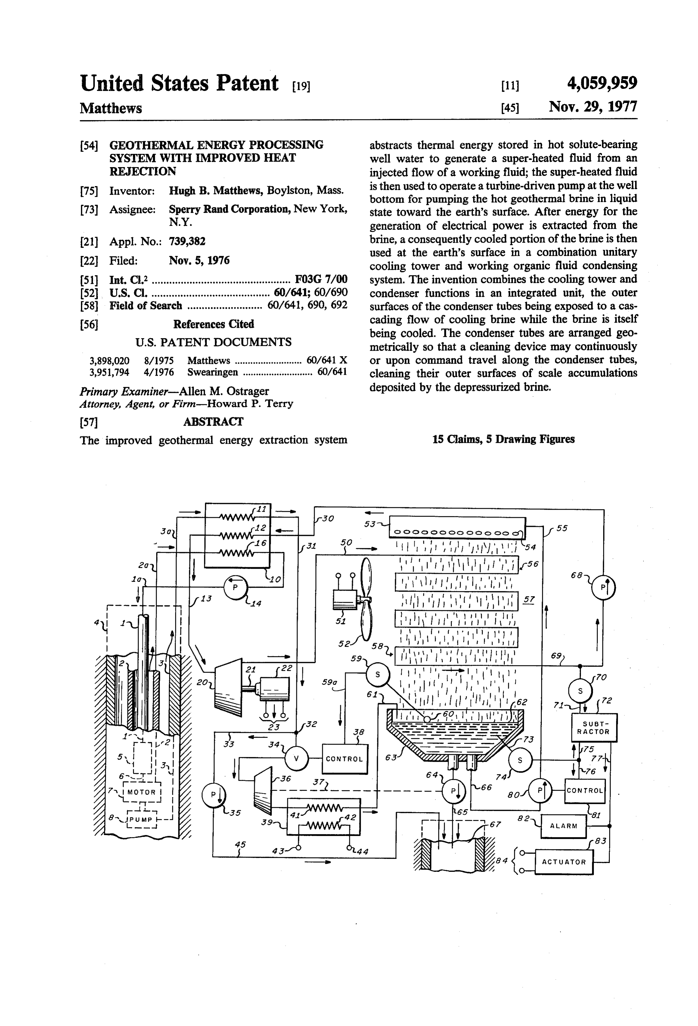
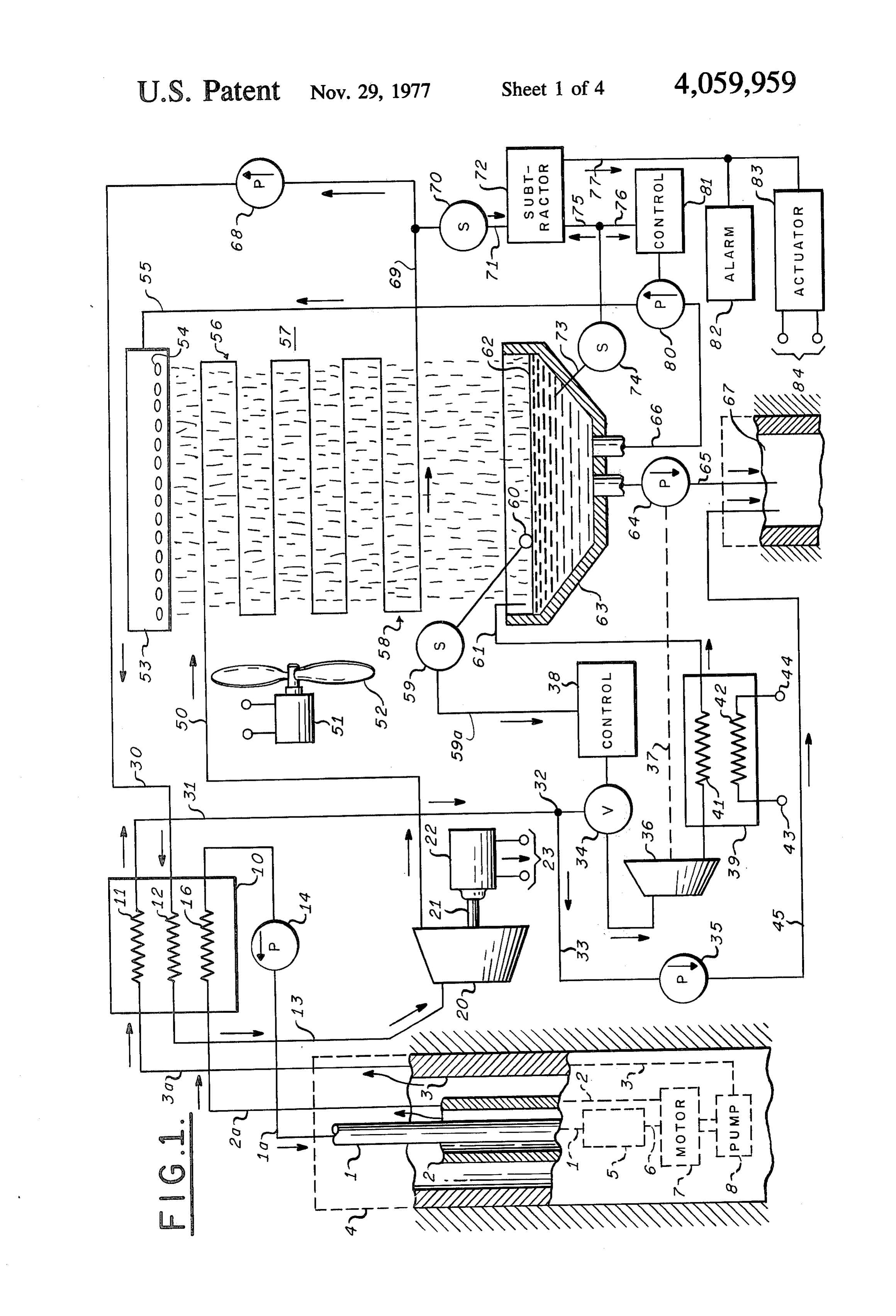
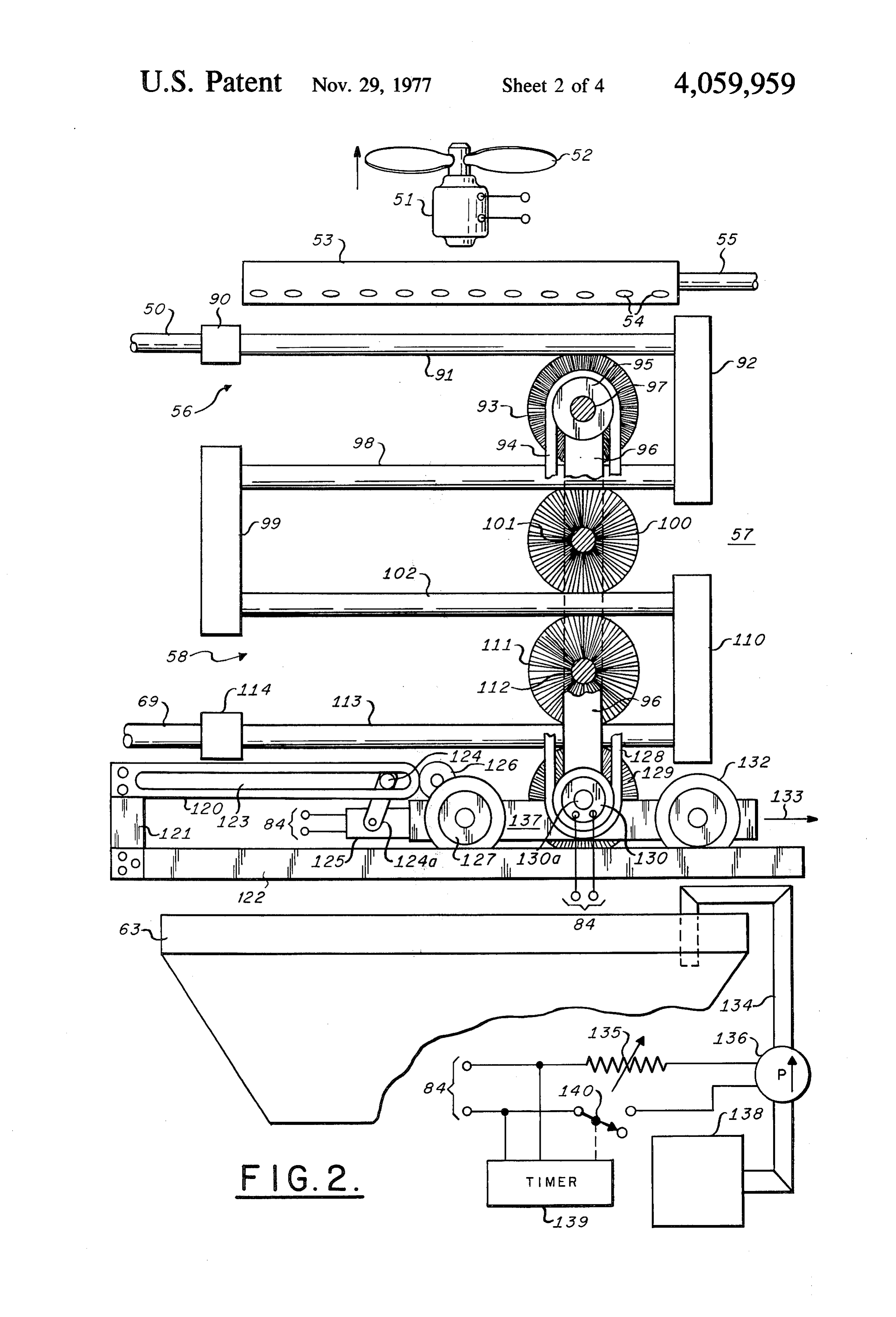
exchanger turbine-alternator combination for genera BRIEF DESCRIPTION OF THE DRAWINGS tion of electrical power. Residual brine is pumped back into the earth, while the clean, cooled liquid is regener FIG. 1 is an elevation view, partly in cross-section, of ated at the surface-located system and is returned to the the deep well geothermal energy conversion system and deep well pumping system for generating vapor and 60 of cooperating surface-located control and power gen also may be used for lubrication of fluid bearings sup eration apparatus;
porting the turbine-driven pump system. The patents FIG. 2 is an elevation view, partly cut away, of one also illustrate improvement features in the form of hy form of cleaning apparatus for use in the apparatus of drodynamic radial and thrust bearings and pressurized FIG, .
liquid bearing lubrication means. A reverse flow, deep 65 FIG. 3 is an elevation view of a second form of the well vapor turbine motor of compact nature is also cleaning apparatus.
disclosed, along with features of surface control and FIG. 4 is an elevation view of an alternative portion power generation systems. of the FIG. 3 arrangement.
Page 7
FIG. 5 is an elevation view in partial cross section of exchanging thermal energy by direct thermal conduc an alternative embodiment of the cleaning apparatus of tion through their metal walls or through a suitable fluid FIGS. 2 and 3. disposed in the well known manner about them. The DESCRIPTION OF THE PREFERRED well pump 8 forces the hot brine upward through the EMBODIMENTS annular region between well casing 3 and pipe 2 and pipe 3a and its thermal content is a significant source of
FIG. 1 illustrates one embodiment of the novel geo heat for supply to the input element 11 of device 10. As thermal energy extraction system as being composed of in the aforementioned Matthews U.S. Pat. No. three major sub-systems. The first or geothermal well 3,910,050, the brine passing through element 11 also sub-system extends from its well head 4 located adja 10 passes through pipes 31 and 33 after having been cent the earth's surface for a distance far below that dropped in temperature within heat exchanger 10 and is surface into an effective cavity or region where a copi then fed through pump 35, if needed, and pipes 45 into ous supply of extremely hot water or brine under high reinjection well 67. Thus, the dissolved mineral salts pressure is naturally available. An active turbine motor pumped to the surface in the hot brine in pipes 3 and 3a 7 and a brine pump 8 are located adjacent the hot water 15 are returned harmlessly into the ground. reservoir within a conventional well casing pipe 3 for As is described in the aforementioned Matthews U.S. operation in the manner generally described in the Pat. No. 3,910,050, other sources of geothermal energy aforementioned Matthews U.S. Pat. No. 3,824,793 and may also be employed to add thermal energy to heat 3,910,050 and elsewhere. In such prior systems, a work exchanger 10, such as the working fluid exhausted by ing fluid is turned to vapor in a vapor generator 5 pipe 2a from the deep well turbine 7 and flowing up heated by the flow of hot brine past it in well casing 3. ward in the annulus between pipes 1 and 2. This exhaust The vapor passes through pipe 6 to drive a turbine fluid may be allowed to flow through pipe 2a into a heat motor 7 which thereby drives the brine pump 8. The exchanger element 16 also located within device 10 for exhausted vapor flows from turbine motor 7 via pipe 2 forced flow by pump 14 after cooling or condensation, to the earth's surface, there to be condensed and re 25 through pipes 1a and 1 back into the deep well heat turned in liquid form via pipe 1 to steam generator 5. exchanger or vapor generator 5 associated with well While the apparatus of the present invention is illus turbine 7, as described in the Matthew's U.S. Pat. No. trated in operation with a particular type of geothermal 3,910,050. The exhaust working fluid is thus used bene well pumping arrangement, it will be understood that it ficially in this way to increase the operating efficiency is equally useful with other kinds of energy extraction 30 of the present invention.
systems, including that of the aforementioned H. B. In any event, the condensed working fluid may be Matthews U.S. patent application Ser. No. 674,243. It returned, for example, for re-use in the deep well appa will be apparent that the system of the Matthews U.S. ratus, as is indicated in FIG. 1. The exhaust working Pat. No. 3,824,793, for example, may convey significant vapor in pipe 2a passes through an input element 16 of amounts of energy to the surface energy conversion 35 heat exchanger 10. The condensed working fluid passes means including heat exchanger 10 both through the from element 16 through pump 14 into pipe 1a for re exhaust vapor in pipe 2a and the brine flowing in the use within geothermal well turbine 7. The working fluid well casing extension 3a, the relative proportions being may be pure water or another similar material. Liquid a matter of design choice. For example, the system of and vapor phases may be employed in the cycle or the Matthews U.S. Pat. No. 3,824,793 transfers much of 40 solely a supercritical liquid phase may be employed, as its thermal energy to surface power conversion appara taught in the aforementioned Matthews patent applica tus using the brine medium. On the other hand, in the tion Ser. No. 674,243.
Matthews application Ser. No. 674,243, the extended The major elements for supply of heat into boiler down-well heat exchanger transfers the major part of heat exchanger device 10 have been described. This the heat in the upward flowing brine into the descend 45 heat is removed and used in a substantially conventional ing supercritical fluid, the brine being normally re manner to operate the surface-located main fluid tur turned at the earth's surface directly into a reinjection bine 20. For this purpose, fluid which may be in the well. A second sub-system of the present invention in form of a halocarbon organic material is supplied by the form of a brine reinjection well 67 also extends from feed pump 68 via pipe 30 to the heat exchanger element a location at the earth's surface into deep earth strata SO 12 of heat exchanger element 12 of heat exchanger which may be horizontally spaced from the aforemen device 10. Flow of the liquid in element 12 is counter to tioned hot brine source. the direction of flow of heat in elements 11 and 16. The Apparatus at the earth's surface forms a third sub-sys liquid in element 12 may thus evaporate, consequently tem and cooperates with the geothermal and reinjection generating high temperature, highly energetic vapor well system according to the present invention, as is 55 coupled via pipe 13 into the input stage of multi-stage illustrated in FIG.1. It will be understood that an objec power turbine 20. After performing useful work therein tive of the invention is to generate large quantities of by driving shaft 21 and generator 22, the power turbine electrical power at terminals 23 at the earth's surface exhaust is fed by pipe 50 into a novel condensing system using a conventional fluid turbine 20 driving the electri 57 with an initial loop 56. The condensed organic fluid cal power generator 22, both preferably located at 60 exits at the final loop 58 of system 57 and is pumped ground level. For this purpose, hot brine is pumped to through pipe 69 by pump 68 into pipe 30, pipe 30 pro the earth's surface by the geothermal well pump 8, viding the input coupling to heat exchanger element 12. being fed by casing 3 and its extension 3a to element 11 In this manner, the fluid for driving the main power of a conventional boiler-heat exchanger device 10. Ap turbine 20 is continuously re-cycled. paratus 10 is a conventional closed tank-like device 65 . It will be understood that the apparatus, as thus far designed to exchange heat between conventional heat described, consists in one form of a deeply submerged exchanger elements 11 and 12 located therein. Elements super-heated steam generator 5 for driving a turbine 7 11 and 12 may take the forms of lineal or coiled pipes which, in turn, drives a hot brine pump 8. Clean water,
Page 8
formed by condensing clean steam in condenser 15, is 57, cooling the exhaust organic fluid flowing within it. supplied to be converted within vapor generator 5 into The cascade of brine droplets is collected by wet well highly energetic steam for driving the geothermal well 63 and the level 62 of brine in wet well 63 is also deter turbine 7. The brine pump 8 serves to increase the pres mined, in part, by the flow of additional brine provided sure level of the hot brine so that it reaches the surface 5 by valve 34 and in pipe 61. It is seen that the falling located heat exchanger 10 at the earth's surface still well brine, which may readily be broken up into droplets by above its saturation pressure and so that it may never, a conventional arrangement of fill (not shown) is cooled by flashing into steam, produce undesirable mineral by evaporation from the droplet surfacs. Such evapora deposition. tive cooling may be enhanced by moving air through According to the invention, a lower cost is achieved O the droplet shower as generally indicated by the fan 52 for the geothermal power extraction system and the driven by motor 51 so that a substantial volume of rap efficiency of the apparatus for condensing the organic idly moving air passes through the shower. In turn, the exhaust fluid from the main power turbine 20 is signifi droplets cool the pipes of array 57 and the organic cantly increased. The invention achieves this desirable vapor flowing within the array, condensing it. result by combining in a novel manner the functions of 15 The fan 52 may be arranged with appropriate duct a cooling tower and fluid condenser system and fur ing, for example, so that a major part of the moving air nishes a means for using a portion of the usually highly flows parallel to and opposite the direction of flow of contaminated geothermal brine as the condenser cool the droplet shower. In general, the fan 52 and motor 51 ant fluid. At the same time, it permits control over foul may be provided with a conventional casing and may be ing and scaling of heat transfer surfaces by salts precipi 20 supported by conventional supports (not shown) as will tating from the geothermal brine itself. Thus, the avail the other elements of the condensing system 57 be sup ability of copious clean cooling water sources (lakes, ported in fixed relation by means well known to those rivers, etcetera) in the near vicinity of the geothermal skilled in the art. A plurality of centrifugal blowers may power plant is no longer a significant problem. The be employed. It will further be recognized that the invention thus permits conservation of water on the one 25 condensing system may employ a plurality of condens hand and, on the other hand, overcomes the problems ing elements 57 forming a parallel-fed rectangular tridi of the usual situation in which copious supplies of clean mensional serpentine array, with a plurality of distribu cooling water are not at all available in the vicinity of tion manifolds 53 above each element of the array, all the geothermal well site. The cooling water may even parts cooperating with a wet well extending therebelow by augmented by using highly contaminated water such 30 at right angles to the plane of FIG. 1. Other known as the saline water of the Salton Sea. types of condenser configurations, including the helical As previously noted, the novel system of FIG. 1 array illustrated in FIG. 4, may equally well be em returns the brine after its passage through the primary ployed in the invention.
heat exchanger element 11 via pipes 31, 33, and 45 to the According to the invention, it is desired that the wet reinjection well 67. A second portion of the cooled 35 well 63 be maintained filled with brine at a substantially brine in pipe 31 branches at the junction 32 and, as constant predetermined level 62. Flow of brine solution determined by the setting of valve 34, passes through into it and especially out of it is designed to flush any pipe 61 into the wet well or sump 63 of the combination accumulation of solid material precipitated from the condensing system 57. If desired, some energy remain brine solution in tank 63 through pump 64 into reinser ing in the cooled brine may be salvaged at this point. 40 tion well 67. Accordingly, there is provided a conven For example, power to drive the second reinjection tional liquid level sensor 59 having, for example, a ball well pump 64 may be supplied by arranging that the float 60 residing on the brine surface 62. Sensor 59 may brine passing through valve 34 into wet well 63 drive an be of the type supplying an electrical output signal auxiliary turbine 36 provided with a mechanical shaft proportional to the brine liquid level via electrical lead 37 or other power transfer link for operating the second 45 59a to a conventional valve controller 38. Controller 38 reinjection pump 64. The purpose of pump 64 is to may be a conventional device which yields a command pump brine from wet well 63 through pipe 65 into rein signal related to the error in the liquid level from a jection well 67. In any case, it may be desirable to pre desired reference value. Conventional on-off control of cool the brine in pipe 61 after passage through turbine the position of valve 34 is also readily effected. It will be 36, as by passing it through a condensing element 41 of 50 observed that the second reinjection pump 64 is oper a condenser 39. Condenser 39 may be cooled in a con ated generally at the same time that brine is being sup ventional manner, as by including a second heat ex plied to the wet well 63 under command of controller changer element 42 therein, joined at couplings 43 and 38; evidently, the rate of flow in pipe 61 is designed to 44 to a piping loop system circulating coolant, for exam be greater than that through reinjection pipe 65 so that ple, through a conventional cooling tower (not shown). 55 the desired design liquid level 62 is ultimately reached The flow of cooled brine through pipe 61 into wet well and valve 34 is then automatically closed. 63 may be continuously or manually controlled, or According to the invention, the rate of pumping brine preferably will be monitored by the liquid-level ball from wet well 63 by pump 80 into the distribution mani float sensor 59, 60, as will be explained. fold 53 is controlled according to the ambient tempera For cooling the coils such as coils 56, 58 of the con ture so that the content of wet well 63 does not freeze in densing system 57, brine from the wet well 63 is extreme weather. For example, as the ambient tempera pumped by pump 80 through pipe 66 into pipe 55 up ture approaches the freezing level, the rate of flow ward to a distribution manifold 53 at the top of the induced by pump 80 is accordingly decreased. The condensing array of pipes. Thus, there is a large volume desired control is accomplished by a conventional con flow of cooled brine from wet tank 63 that is emitted 65 troller 81 responsive to a conventional sensor 74 having into the atmosphere by a suitable array or arrays of a suitable probe 73 for sensing the temperature of the orifices, such as orifice 54, in the lower surface of mani brine in wet well 63, The temperature sensor 74 may be fold 53 so as to fall downward over the condenser array selected from conventional devices adapted to yield an
Page 9
electrical output signal on lead 76 substantially propor may be continuously operated for the purpose. As in tional to the brine temperature. The signal on lead 76 is FIG. 1, a parallel array of serpentine condensing pipe used to operate a conventional controller 81 which systems 57 is employed in FIG. 2, fed via input pipe 50 determines the rate of operation of an electrical motor with exhaust vapor from the main power turbine 20, integral within pump 80. The rate of brine flow through 5 and supplying condensed fluid via output pipe 69 and pump 80 is generally maintained constant, but the con pump 68 to heat exchanger element 12. Other elements troller 81 causes speed reduction to occur at a predeter also used in FIG. 1 appear in FIG. 2 and bear corre mined temperature somewhat above the freezing tem sponding reference materials, including the brine distri perature of the brine in wet tank 63. A simple thermal bution manifold 53, motor 51 and its associated fan 52, relay may thus be used to reduce the speed of pump 80 10 and the wet tank 63; appropriate controls such as dis from its normal fixed rate to a second but reduced rate, cussed in connection with FIG. 1 may also be employed the reduction occurring at and below the predeter in the system of FIG. 2. Conventional manifolds 90, 92, mined temperature. The reduced brine flow in the cas 99, 110, and 114 cooperate in the usual manner with cade from distributor manifold 53 automatically permits corresponding arrays of the condenser pipes, such as the brine to be additionally heated during its descent to 15 shown at 91, 98, 102, and 113. The fan 52, distribution wet sink 63, so that the temperature of the brine therein manifold 53, condenser array 57, and the wet well 63, as rises to a safe level above freezing. Controller 81 may well as a pair of rails 122 or tracks along which the also operate a visual or audible alarm, if desired. brush carriage 137 is translated, are supported by a The efficiency of the novel geothermal energy ex conventional framework, not shown in the drawing traction system may be undesirably diminished by the since its nature will be evident to those skilled in the art accumulation of scale, films, or other deposits that may and for the sake of affording a clear illustration of the precipitate from the cooling brine onto the exterior invention.
surfaces of the condenser pipes in array 57, because heat . As has been discussed, the condenser array 57 may flow from the organic fluid into the droplet shower is consist of large pluralities of coolant pipes lying in the evidently decreased by the presence of such relatively 25 respective horizontal planes in which coolant pipes 91, thermally insulating solid layers. According to the in 98, 102, and 113 are disposed. Each plane, such as the vention, the build-up of such solid layers to significant plane of pipes 98, is served, for example, by two op depth is detected by noting any increase in a parameter posed cylindrical rotary brushes, such as brushes 93 and proportional to the temperature or to the pressure of the 100; the brushes may fully envelope pipes 98 as the organic vapor at the output end of condensing loop 58 30 brushes are spun about their respective shafts 97, 101. with respect to the temperature of the brine in wet well Such a rotary brush may also be disposed between the 63. Thus, according to the invention, a conventional brine distribution manifold 53 and the pipes 91. temperature sensor 70 coupled to the interior of con The several rotary brushes 93, 100, 111, 129 spin on densing loop 58 may supply an electrical control signal respective parallel shafts 97, 101, 112, 130a that are via lead 71 proportional to that temperature to a con 35 journalled in upright frame elements 96 at each end of ventional comparator or analog subtraction circuit 72. the several shafts. Upright frames 96 are adapted to A pressure sensor may evidently be substituted for tem move back and forth, being mounted on the horizon perature sensor 70. It will, of course, be understood that tally translatable carriage 137 whose pairs of flanged these and any of the other sensors provided according wheels 127, 132 respectively engage pairs of rails 122 to the invention may be equipped with suitable displays and are driven by motor 126 in a conventional manner. allowing visual observation of the respective functions Wheels 127, 132 may alternatively take the form of measured by the individual sensors. Since subtractor 72 flanged gears with a toothed circular surface cooperat also receives, on electrical lead 75, the output of the ing with the teeth of pairs of racks substituted for rails aforementioned temperature sensor 74, the output of 122. Motor 126 may also be used to drive brushes 93, subtractor 72 on electrical lead 77 is proportional to the 45 100, 111, 129 through suitable belts, shafts, or gearing. difference between the temperatures of the cooled or In FIG. 2, a separate motor 130 mounted on the up ganic vapor and the brine in the wet well 63. If the right 96 of carriage 137 is used to drive the several temperature of the organic fluid flowing in the output brushes. Motor 130 drives brush 129 directly, its rotor loop 58 is too high with respect to the brine tempera being coupled mechanically to the shaft 130a of brush ture, the indication is that the cooling is not as effective 50 129; motor 130 is equipped with a pulley whereby its as desired for efficient condenser action, and this ele associated V-belt 128 drives rotary brush 111. Pairs of vated signal may then be passed by electrical lead 77, pulleys and V-belts cooperate to drive each successive for example, to operate a visual or audible alarm 82. It brushshaft until a final V-belt 94 drives the single pulley will be understood that the alarm may be of a conven 95 associated with rotary brush93, for example. It will tional type having a threshold limit only above which 55 be apparent to those skilled in the art that other known alarm operation actually occurs. The signal on lead 77 drive mechanisms may be substituted for spinning the may alternatively or additionally be used to operate a brushes 93, 100, 111, and 129 or that individual motors control or actuator 83 whose output leads 84 are con may be used on each shaft. Motor 130 may be driven nected to apparatus for causing removal of the unde constantly or may be turned on or off at the will of the sired scale or other solid residue from the outer surfaces operator. Alternatively, operation of motor 130 and of the pipes of condenser assembly 57. consequently of brushes 93, 100, 111, and 129 may be Further, according to the invention, scale or other made automatic by use of the aforementioned electrical undesired solid material may be removed from the pipes actuation signal provided on leads 84 of the FIG. 1 of condenser assembly 57 by several methods, particu apparatus.
larly by energetic brushing of the surfaces, as in FIG. 2, 65 The same electrical signal from terminals 84 of FIG. or by the impact of a high pressure liquid spray, as in 1 may be used to cause back and forth translation of FIGS. 3, 4, and 5. In the particular form shown in FIG. carriage 137 by proper operation of motor 126 which 2, a mobile assembly of rotating brushes on carriage 137 drives the flanged carriage wheel 127. As shown in
Page 10
figure, carriage 137 has nearly reached the limit of its needle-like fluid jets are directed in many different di rightward travel (arrow 133), at which point the slot rections toward the outer surfaces of condenser pipes 123 in the horizontal slotted member 120, fixed relative such as pipes 91 and 98. The sharp, high pressure spray, to rails 122 as by support 121, will stop the motion of pin aided by the dissolved detergent material, readily re 124, moving arm 124a of reversing switch 125 to the left 5 moves the accumulated layer of brine solute. so as to reverse the operation of motor 126 and conse The action of the spray may be enhanced by supply quently the direction of translation of carriage 137. ing a motor and an appropriate drive mechanism for When carriage 137 reaches its leftward extreme posi spinning each of the several pipes 146 each about their tion, pin 124 impacts the opposite end of slot 123, again individual axes. A similar effect is produced by pulsing reversing travel of carriage 137. The cycling continues 10 the pressure supplied by pump 149 by any convenient as long as there is a command signal on terminals 84. means. A further alternative mechanism is illustrated in If desired, the cleaning efficiency of the rotary brush FIG. 4, where the manifold 146, fed from pipe 148 system may be enhanced by adding a non-foaming de through flexible hose or pipe 157, is provided with tergent to the brine solution in wet well 63. For this plural roller drums 155 riding in a pair of U-shaped purpose, the invention provides a reservoir 138 of liquid 15 channels 156. A motor 161 drives a disk 162 having an detergent which is pumped by pump 136 via pipe 134 eccentric pin 160 and a connecting rod 159 linked from into the wet tank 63 on command. Pump 136 may be pin 160 to manifold 145 through pin 158. Rotation of operated at a speed determined by a control such as motor 161 causes oscillatory or dithered translation of manually adjustable variable resistor 135 as long as the the spray-generating assembly so that all parts of the signal on terminals 84 of FIG. 1 is present. On the other 20 surface to be cleaned are exposed to the high pressure hand, it may be preferred to operate pump 136 at full cleaning spray for loosening and removing undesired pumping speed for a short time as soon as the electrical scales. Channels 156 and motor 161 are supported by command signal on terminals 84 is present. Such may be the framework supporting the condenser pipe system accomplished by having the command signal operate a and the distribution manifold 53, which latter may have timer 139 arranged to close switch 140 at once and to 25 a lower face 89 with a multiplicity of orifices for form open it at a predetermined later time when the concen ing the droplet shower previously discussed. It will be tration of detergent in wet tank 63 is adequate. Switch apparent that cleaning arrays such as that including 139 may also be manually operated. pipes 146 may readily be translated, when not in use, out If desired, the rotary brush system may be moved of the apparatus by using a suitably supported trolley entirely from the condensing unit 57 by supporting the 30 system or that they may be operated continuously brush shafts from one end only and by arranging that within the condenser array.
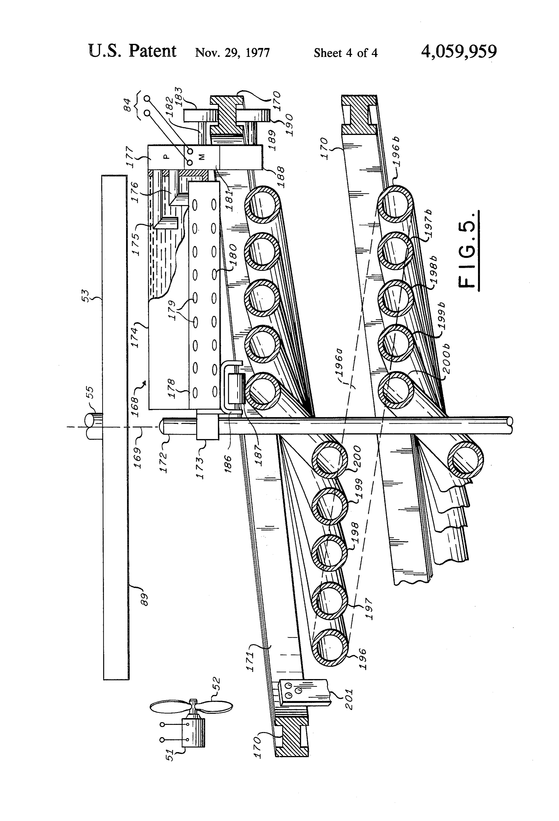
their support system be translated at right angles to the A further preferred form of the invention for particu plane of the drawing of FIG. 2. Further, it will be un lar applications in which high pressure liquid cleaning derstood that carriage 137 may readily be operated jets are desired is illustrated in FIG. 5. This form of the from overhead rails supported, for example, above the 35 invention is of particular interest for use in a condenser brine distribution manifold 53. It will be additionally system having a vertical axis 169 in which the con understood that actuator 83 may be made to operate denser pipes to be cooled by brine droplets from the motor 130 or, more particularly, the cleaning brushes brine distribution manifold 53 take the form of an assem themselves at a rate generally proportional to the mea bly of nested, generally coaxial, helical condenser pipes, sured thickness of the undesired scale deposit. 40 one half turn of which assembly is shown in section as A preferred embodiment of the condenser pipe clean including helical half-turn segments 196, 197, 198, 199, ing apparatus is illustrated in FIG. 3, wherein high 200. It will be understood that these helical pipes extend pressure liquid spray is directed against the surface to be continuously from the top to the bottom of the con cleared of brine-deposits, the spray consisting of the denser volume, being fed by an input manifold like brine solution taken from wet tank 63 with detergent 45 manifold 90 of FIG. 2 and exhausting into a manifold added as previously discussed. While this configuration 114 such as is also seen in FIG. 2. The continuity of the is illustrated in lieu of the rotating brush system, it will coils is indicated by the half turns (sectioned) 196b, be understood that brushes and a high pressure spray 197b, 198b, 199b, and 200b and further by way of exam mechanism may be used cooperatively. ple by the dotted connection 196 between half turns 196 The illustration in FIG. 3 is somewhat analogous to a 50 and 196b, view taken at right angles to FIG. 2 with the brush In the embodiment of FIG. 5, use is not made of a mechanism removed, so that the condenser pipes 91 are carriage which is simply translated along a straight now seen in section, each joined to the manifold 90 that path, but there is used a carriage 168 which follows a is fed by the turbineexhaust pipe 50. Also shown in the helical path up and down the condenser assembly. In fragmentary view is a cross-section of the next lower 55 effect, the path is generated by continuously rotating array of condenser pipes 98, each joined to the next the radially disposed carriage 168 while continuously lower manifold 92. In the figure, it is indicated that each lowering (or raising) the intersection of the associated adjacent pair of condenser pipe assemblies, such as radius with respect to axis 169. The double track 171 has those of the respective condenser pipes 91 and 98, are an H-shaped cross section 170 and it also forms a helix spaced apart to accommodate a high pressure jet spray 60 with respect to axis 169, lying outside of the volume cleaning device. Brine from wet tank 63 containing occupied by the condenser pipe assembly and supported detergent, if desired, is pumped through pipes 150 and in a conventional manner by a suitable framework indi 148 by high pressure pump 149 into the distribution cated at 201. Wheel or gear 182 on shaft 182 is driven manifold 145. Pump 149 is driven by an integral motor reversibly by motor 181 mounted on the frame 188 of which may be excited by the signal on terminals 84 of 65 the carriage 168; the second guide wheel 190 on shaft FIG. 1. Each pipe 146 is provided along its length and 189 is also journaled in frame 188 and may be an idler about its circumference with a multitude of high pres wheel. Wheels 183 and 190 cooperate with the opposed sure orifices, such as orifice 147, so that high pressure tracks in helical guide 171 is supporting one end of the
Page 11
carriage 168, as well as enabling that end to be driven surfaces of the inevitable scaling caused by the precipi along track 171. The inner end of frame 188 may be tation of carbonates, silica, and other solutes from the supported with respect to an inner condenser helix 200 unpressurized brine. Thus, the combined system fur by an idler drum 187; drum or roller 187 is journaled in nishes a means for using a portion of the contaminated yoke 186 affixed to the inner end of frame 188, the drum 5 geothermal brine as the organic fluid condenser coolant 187 engaging at least one of the condenser pipes, such as and, at the same time, for controlling the fouling and pipe 200. If desired, drum 187 may be positively driven scaling of the heat transfer surfaces contacted by the by a motor such as motor 181. Means for reversing the brine.
carriage 168 at each end of its helical path may be sup While the invention has been described in its pre plied in a conventional manner, such as in the general O ferred embodiments, it is to be understood that the manner illustrated in FIG. 2. The inner end of the radi words which have been used are words of description ally disposed frame 188 may be coupled to a yoke 173 rather than of limitation and that changes within the loosely fitting around the vertical rod or pipe 172 lying purview of the appended claims may be made without on axis 169; yoke 173 acts as a further guidance aid. departure from the true scope and spirit of the invention The function of the carriage 168 and of its frame 188 15 in its broader aspects.
is to support means for directing highly energetic jets of I claim:
brine usually containing non-foaming detergent mate 1. Geothermal deep well energy extraction apparatus rial at the outer surfaces of condenser coils 196 through of the kind in which solute-bearing water is pumped to 200 for removal of undesired scale deposits. For this a station at the earth's surface utilizing thermal energy purpose, the carriage 168 includes a distributor mani 20 extracted within said well from said solute-bearing fold 178 for directing such jets through orifices 180 water for operating turbine-motor driven electrical toward such surfaces below manifold 178 and also generator means at said station, a major portion of said through orifices 179 directed upwardly toward other solute-bearing water being returned from said station surfaces similarly to be cleaned of scale or brine depos into reinjection well means, said extraction apparatus its. Thus, while traversing its spiral path, the carriage 25 further including:
168 and its liquid jets simultaneously clean contiguous coupling means for supplying a working fluid utiliz condenser pipe surfaces above and below manifold 178, ing a portion of said extracted thermal energy to an the manifold 178 being disposed in front of tank 174. input of said turbine motor means, Liquid for performing the cleaning function is col condenser conduit means coupled to the output of lected in the open tank 174 as it showers down in the 30 said turbine motor means for condensing said form of droplets from the distribution manifold 53. The working fluid and returning said condensed work liquid level in tank 174 may be augmented at a particu ing fluid to said coupling means, lar point in the trajectory of carriage 168, as at its bot manifold distributor means for enveloping said con tom reversal point, and detergent material may be auto denser conduit means in a coolant shower in drop matically or manually added there to reservoir 174, 35 let form,
Motor 181, which drives wheel 183, may be used wet well tank means for collecting said coolant through suitable step up gearing to drive a high pressure shower after cooling said condenser conduit pump 177; when operating, pump 177 takes liquid out of means, - tank 176 into the jet manifold 178 for cleaning the con air circulating means for cooling said droplets of said denser pipe assembly. It will be understood that the 40 coolant shower while descending from said mani water jets may contain, in addition to or alternaive to a fold distributor means to said wet well tank means, detergent material certain well known soft blast media first pump means for conveying coolant from said to aid the cleaning function. wet well tank means to said manifold distributor Accordingly, it is seen that the invention overcomes means, and a problem which has been faced at some considerable 45 control means for selecting a minor portion of said expense at certain geothermal energy sites. By way of solute-bearing water before said major portion is example, a one thousand gallon per minute geothermal returned to said reinjection well means for main well would require the evaporation of substantially 200 taining a predetermined liquid level within said wet gallons per minute of water into the atmosphere to cool tank means, the organic fluid condenser and an additional 100 to 200 50 2. Apparatus as described in claim 1 wherein said gallons per minute to pass through the cooling tower in control means comprises:
unevaporated state for controlling the build-up of solid liquid level sensor means for sensing the level of said precipitates and solutes in the wet well of the cooling coolant in said wet well tank, tower. According to the invention, a portion of the well first conduit means for returning said major portion brine successfully performs this function after the brine 55 of said solute-bearing water into said reinjection heat has been usefully extracted in the electrical power well means, generation process. According to the invention, the second conduit means branching from said first con functions of the cooling tower and organic fluid con duit means for supplying said minor portion of said densing system are combined in an integrated unit. The solute-bearing water to said wet well tank means, effective combination of the cooling tower and organic 60 and fluid condenser systems permits operation with a valve means in said second conduit means responsive smaller difference between the wet bulb and condensing - to said liquid level sensor means, temperatures because the cooling water shower is itself 3. Apparatus as described in claim 2 further includ continuously cooled as it cascades over the condenser ling:
pipes. The condenser pipes over which the cooling 65 second pump means at the bottom of said wet well brine cascades are arranged geometrically so that a tank means for pumping solute-bearing water and cleaning device may continuously or upon command particulate matter from said wet well tank means travel along the condenser pipes, cleaning their exterior into said reinjection well means, and
Page 12
fluid motor means responsive to flow of solute-bear second motive means for translating said rotary brush ing water in said second conduit means for driving means along said condenser conduit means, said second pump means. 10. Apparatus as described in claim 8 additionally 4. Apparatus as described in claim 1 further includ including means for adding a non-foaming detergent to ing: 5 said wet well tank means during operation of said means temperature sensor means for sensing the temperature for removing said solute deposits, of said coolant within said wet well tank means, 11. Apparatus as described in claim 9 including means and for cyclically reversing the direction of translation of controller means responsive to said temperature sen said second motive means.
12. Apparatus as described in claim 1 additionally sor means for controlling the rate of operation of 10 including said first pump means. means for removing solute deposits from the outer surfaces of said condenser conduit means com 5. Apparatus as described in claim 1 further includ prising:
means for sensing a function of the temperature of 15 high pressure spray means for impacting at least a portion of the outer surface of said condenser con said condensed working fluid at the output of said duit means with energetic liquid jets, and condenser conduit means for forming a first control pressure pump means for supplying said high pressure signal, spray means with coolant from said wet well tank. temperature sensor means for sensing the temperature 13. Apparatus as described in claim 12 further includ of said coolant within said wet well tank means for 20 ing means for oscillatory translation of said high pres forming a second control signal, subtractor means responsive to said first and second impact of a major portion ofsuch sure spray means in a plane as to insure effective control signals for forming a difference signal, and condenser conduit means with saidouter the surface of said energetic liquid jets.
utilization means responsive to said difference signal. 14. Apparatus as described in claim 1 additionally 6. Apparatus as described in claim 5 wherein said 25 including means for removing solute deposits from the utilization means comprises alarm means for indicating outer surface of said condenser conduit means compris the presence of a predetermined thickness of solute 1ng:
deposit on said condenser conduit means. carriage means, 7. Apparatus as described in claim 5 wherein said high pressure spray means disposed on said carriage utilization means comprises means for removing solute 30 means for impacting at least a portion of the outer deposits from the outer surface of said condenser con surface of said condenser conduit means with ener duit means. getic liquid jets, 8. Apparatus as described in claim 1 additionally collector tank means additionally disposed on said including means for removing solute deposits from the carriage means for collectingaportion of said cool outer surface of said condenser conduit means in the 35 ant shower from said manifold distributor means, presence of said coolant shower. and 9. Apparatus as described in claim 8 wherein said second pump means additionally disposed on said means for removing solute deposits comprises: tank means for conveying coolant from said collec rotary brush means contacting while rotating at least tor tank means to said high pressure spray means, a portion of said outer surface of said condenser 40 15. Apparatus as described in claim 14 further includ means, ing means for translating said carriage means along said first motive means for rotating said rotary brush condenser conduit means.
means, and
Provenance
- Collection
- Cited prior art
- Original PDF
- patentimages.storage.googleapis.com →
- Filed
- 1976-11-05
- Pages
- 12
- Method
- pdftotext (the PDF's own text layer) + pdftoppm 300dpi page scans
- Source
- Google Patents bibliographic record
- Granted
- 1977-11-29
- Inventors
- Hugh B. Matthews; Sperry Rand Corp
- Transcribed from
- patentimages.storage.googleapis.com →