patent · US4378908
Reversible solar assisted heat pump
5 April 1983
Page 1 — bibliographic record
United States Patent (19) 11 4,378,908 Wood 45 Apr. 5, 1983 (54) REVERSIBLE SOLAR ASSISTED HEAT 4,167,965 9/1979 Rogers ........... 237/2 B X PUMP 4,190,199 2/1980 Cawley et al. ...................... 126/49 a- 4,205,718 6/1980 Balch .................................... 165/45 76) Inventor: Robert A. Wood, 59425 10 Mile, Apt. 4,232,820 1 1/1980 Ritter et al. ......................... 237/2 B 6B, South Lyon, Mich. 48178 4,256,475 3/1981 Schafer ........................... 237/2 B X 21 Appl. No.: 101,687 Primary Examiner-Albert J. Makay 22 Filed: Dec. 10, 1979 Attorney, Agent, or Firm-Harness, Dickey & Pierce 51) Int. Cl. ................................... ... 605D 23/00 ABSTRACT 52 U.S. C. ................................... 237/2 B; 62/324.4; Disclosed is a reversible, solar assisted heating system 62/238.6; 62/235.1; 126/419; 126/427; comprising an unglazed solar heat exchange panel, a 126/418; 165/29 storage tank, and a water source heat pump. In the (58) Field of Search ............... 237/2 B; 62/324.4, 260, heating mode, heat is collected from the air and sun 62/2, 238.6, 235. 1; 126/419, 427; 165/29 through one or more unglazed panels, transferred to a storage tank and then to a heat pump. In the cooling 56) References Cited mode, heat is transferred by the heat pump to the stor
3,039,453 6/1962 Andrassy ............................ 126,420 heat is rejected to the air.
4,020,989 5/1977 Kautz ....... ... 126/431 4,138,996 2/1979 Cartland .............................. 126/420 7 Claims, 7 Drawing Figures
Page 2
Drawing sheet — no readable text.
Page 3
Drawing sheet — no readable text.
Page 4
Drawing sheet — no readable text.
Page 5
unattended, frost will at times block heat transfer from
REVERSIBLE SOLAR ASSISTED HEAT PUMP the outside air to the heat pump. Heat pump COP and heat output capacity decline as frost accumulates. This
FIELD OF THE INVENTION problem is generally dealt with by an energy expensive The present invention relates to a heating system 5 defrosting of the outdoor coil. In an air source heat comprising a reversible, solar assisted water source heat pump, defrosting is usually accomplished by running in pump. More particularly, the present invention relates the air conditioning mode, i.e. withdrawing heat from to a heating system having a heat pump operatively the interior of the building to melt the frost. The contin connected to an unglazed solar panel through a storage O ual reversal of valves and refrigerant is hard on the unit. tank which preferably includes a unitized fluid pumping Service life and reliability of the air source heat pump package with a snow removal mechanism for installa are adversely affected by the defrost cycle. tions where snow accumulation will be a problem. It is manifest that it would be desirable if an economi BACKGROUND AND SUMMARY OF THE cally practical solar heating system could be provided.
This is an object of the present invention wherein an efficient, solar assisted, reversible heating system is
In recent years, the availability of oil and gas has provided. The system of the present invention employs failed to keep up with the demand for energy in the relatively inexpensive, uncovered panels to collect heat United States and other countries. This state of affairs from the sun and/or from the ambient air. The collected has contributed to the rising cost of oil and gas and to 20 heat is transported by fluid to a storage tank which what is commonly referred to as an "energy crisis.' provides a source of heat for a water source heat pump. There is not only concern for the security and economic The system can be reversed for summer cooling. well being of citizens but also concern for the availabil ity of energy for heating of homes and other buildings. tionThe reversible heating system of the present inven efficiently uses energy and involves relatively inex
As a result of these concerns, research and development pensive components which can be easily installed and effort has focused on the development of alternative 25 serviced. Further features, advantages and understand energy sources. Although such alternative energy ing of the present invention will be obtained from the sources include nuclear and other sources, a particu following disclosure taken in conjunction with the ap larly attractive energy source is solar energy. In fact, pended claims and accompanying drawings. various federal and state tax credits are given in the
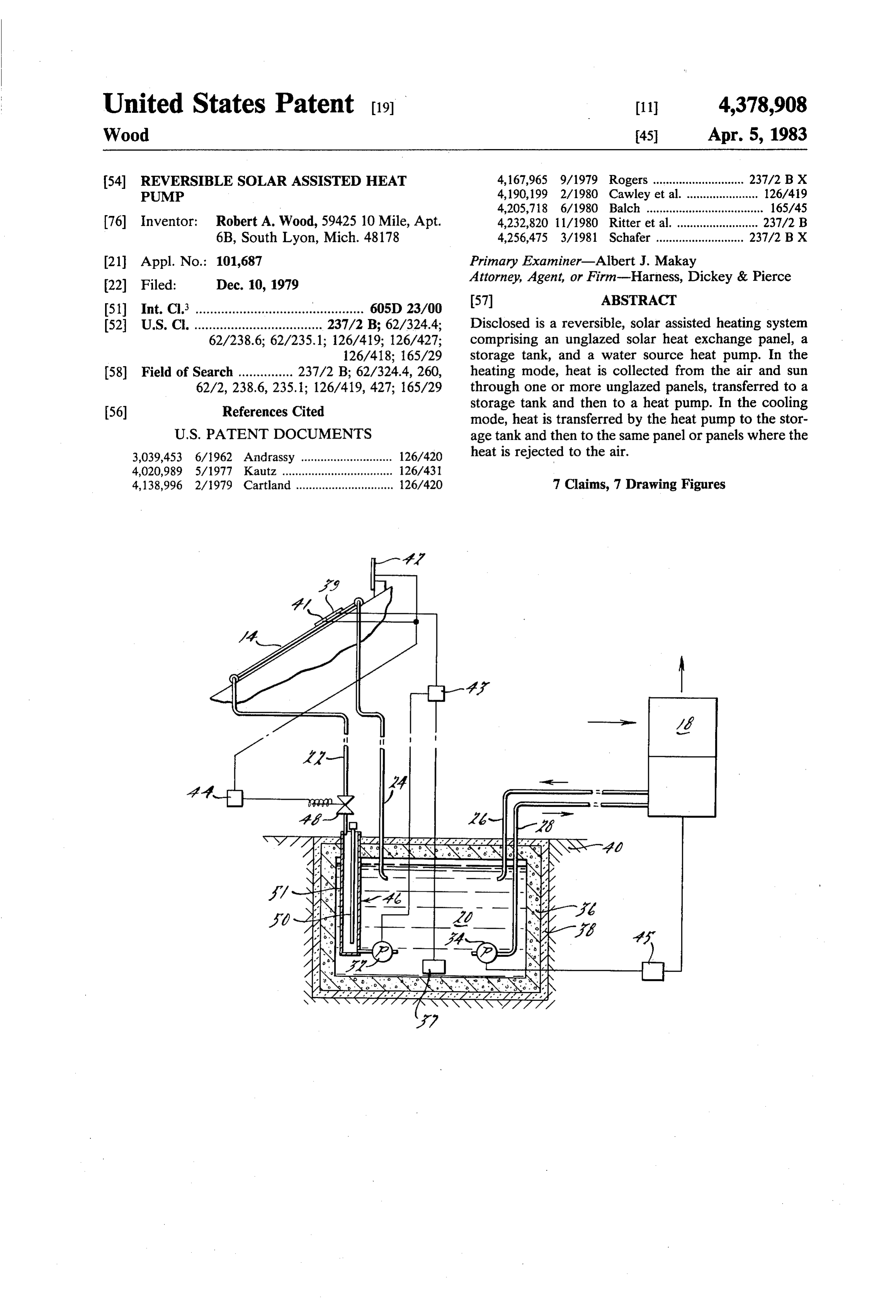
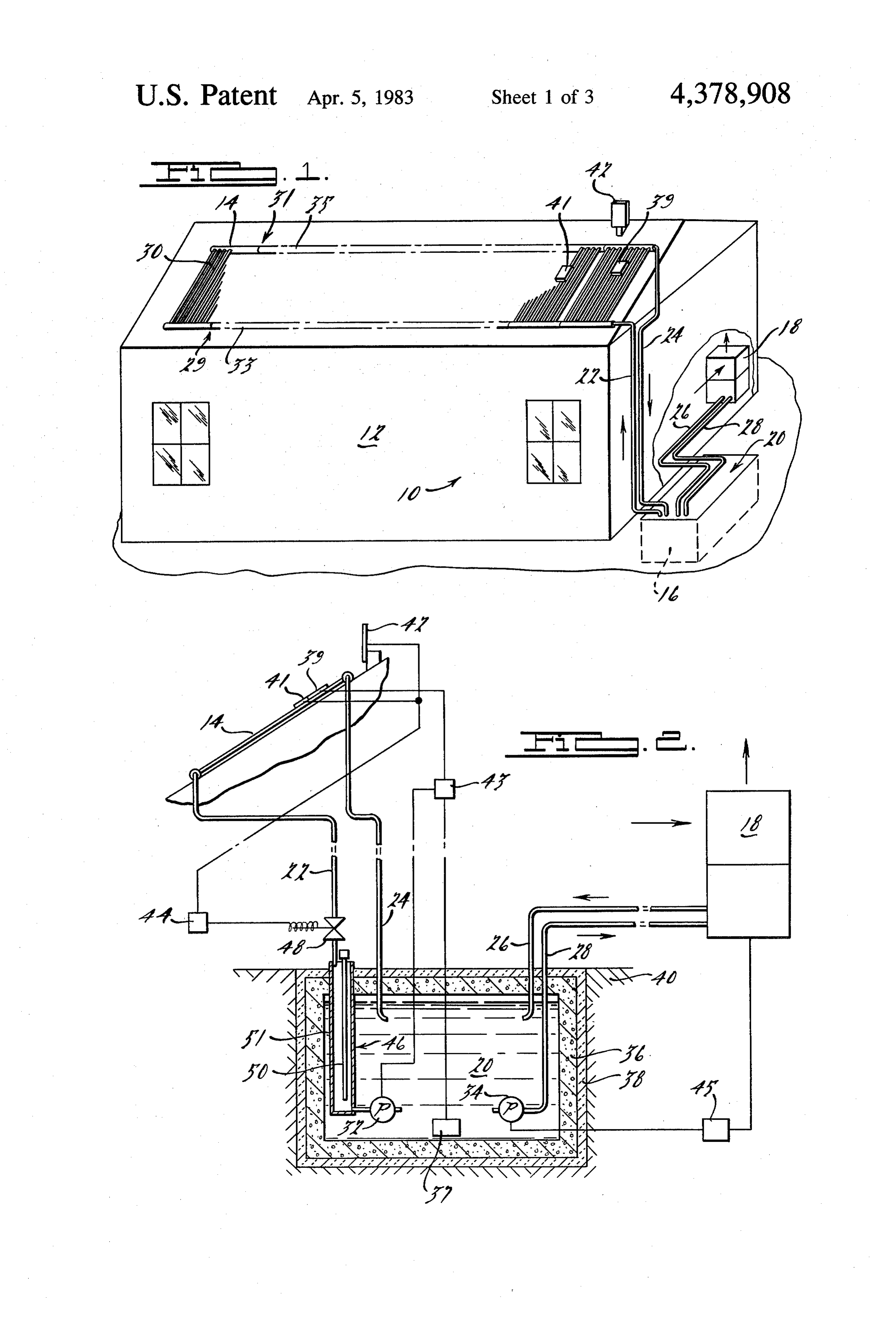
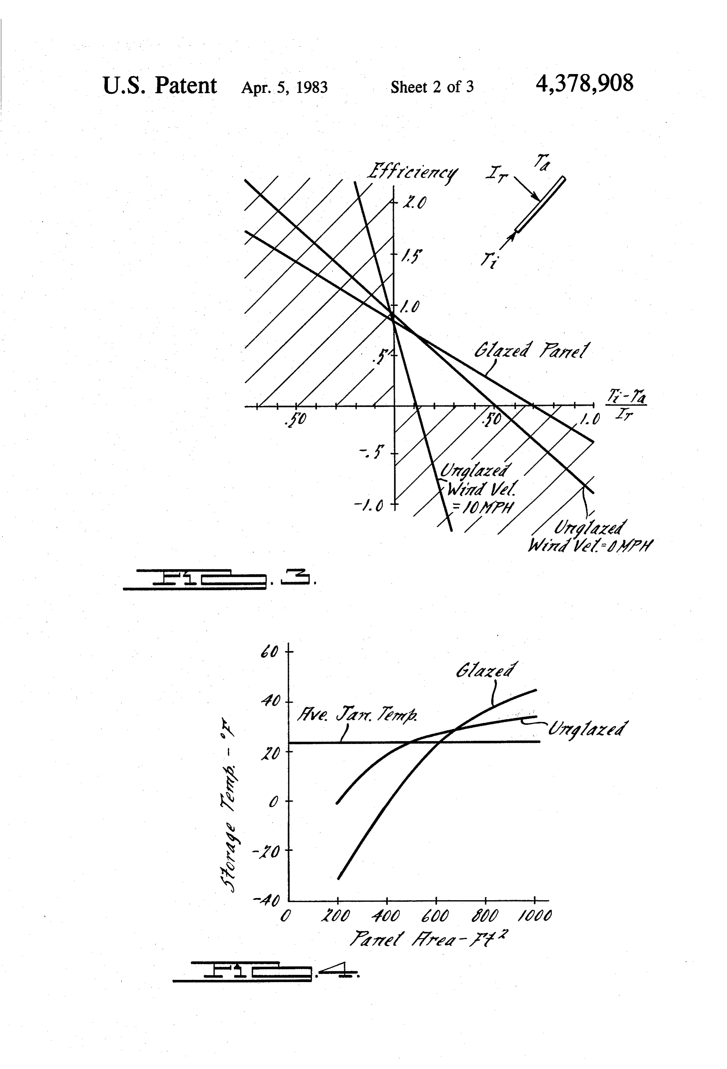
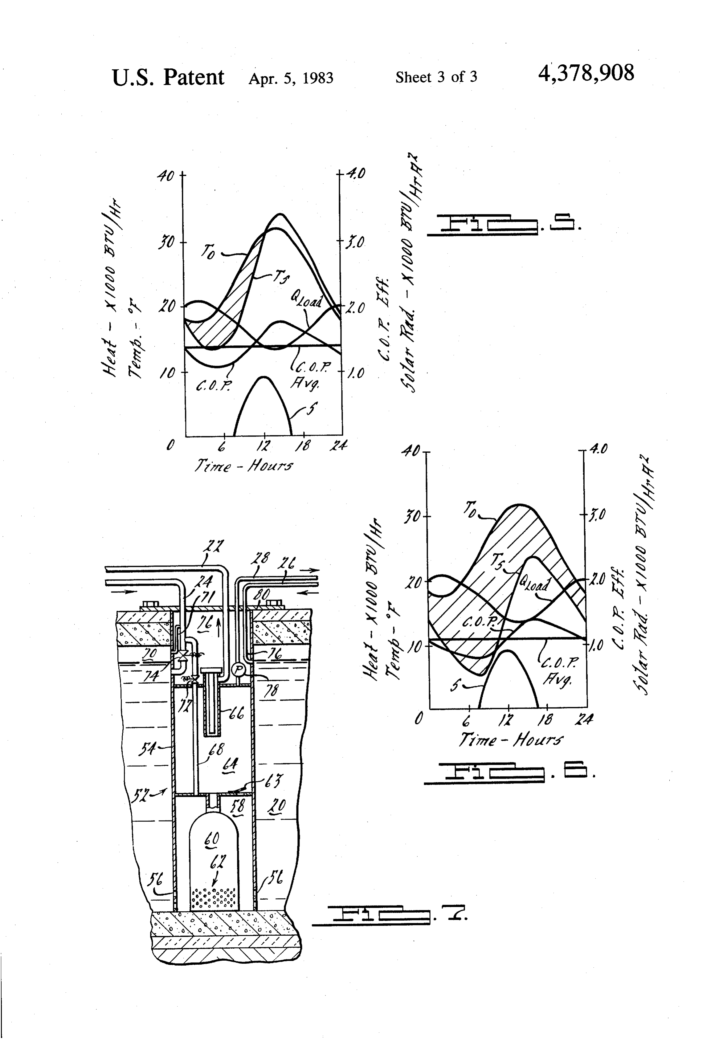
United States to encourage development and use of 30 BRIEF DESCRIPTION OF THE DRAWINGS solar energy technology. FIG. 1 is a perspective view, with portions broken However, solar heating systems encounter several away, of a building equipped with a reversible heating problems which must be overcome in order for such system of the present invention; systems to be cost effective. One problem which must FIG. 2 is a somewhat schematic view of the heating be overcome in order for a solar space heating system to 35 system of the present invention including a vertical be practical is that during the winter when there is the greatest need for heating energy, there is relatively less sectional view of a storage tank of the invention; sunlight available than during the summer. Also, during glazed FIG. 3 is a graph illustrating the efficiency curves of the summer a conventional solar heating system does and unglazed solar panels; FIG. 4 is a graph illustrating average heat transfer not contribute to cooling of the home. In short, at their 40 fluid present state of development it is generally not econom temperatures in a storage tank of the present inven ically practical to purchase and use a conventional solar tion for glazed and unglazed panels in use during a heating system which typically relies on glazed solar typical winter month;
panels. Glazed solar panels are expensive and generally FIG. 5 is a graph illustrating the functioning of a not cost-effective for space heating and cooling. As a 45 heating system in FIGS. 1-2 during a 24 hour period; result, few heating systems rely only on the sun to heat FIG. 6 is a graph similar to that of FIG. 5 but illus the interiors of buildings. trating the functioning of a heating system having Thus, combination systems have been proposed glazed panels substituted for the unglazed panels; and where solar panels are used in combination with an FIG. 7 is a vertical sectional view, broken away, of an auxiliary heating source such as an air source heat 50 unitized fluid pumping package which can be used in pump. The heat pump supplements the solar panels the storage tank of the present invention. when the heating demand exceeds the capacity of the DESCRIPTION OF THE INVENTION solar system. An additional electric resistance heating system may also be required to supplement the heat Now referring to the Figures, FIG. 1 shows a heating pump when the heating demand exceeds its capacity. 55 system 10 of the present invention in operative associa However, such systems have several disadvantages. Air tion with building 12 to provide a heating and cooling source heat pumps collect heat from the air alone and system for the interior spaces thereof. Heating system do not store heat from air at higher day time tempera 10 generally comprises an unglazed heat exchange tures for use at night. Night, obviously, is usually the panel 14, a storage tank 16 and a water-source heat time period of greatest heating demand. This time/tem 60 pump 18. Unglazed panel 14 is adapted for conducting perature relationship is important as the Coefficient of thermal energy between the panel environment and a Performance (COP) of the heat pump and the heat heat transfer fluid in the interior of the panel. It is con output capacity thereof are dependent on the tempera templated that a plurality of panels 14 will normally be ture of the heat source. Thus, at the time of greatest connected in fluid communicating relationship as illus heating demand, the air source heat pump is the least 65 trated in FIG. 1 to provide a greater panel area than efficient and has the least heat output capacity. Another would be had from one panel 14. Conduits 22 and 24 problem with use of air source heat pumps is the forma connect storage tank 16 in fluid communication with tion of frost on the outdoor air heat exchange coil. If left the inlet and outlet, respectively, of panel 14. Conduits
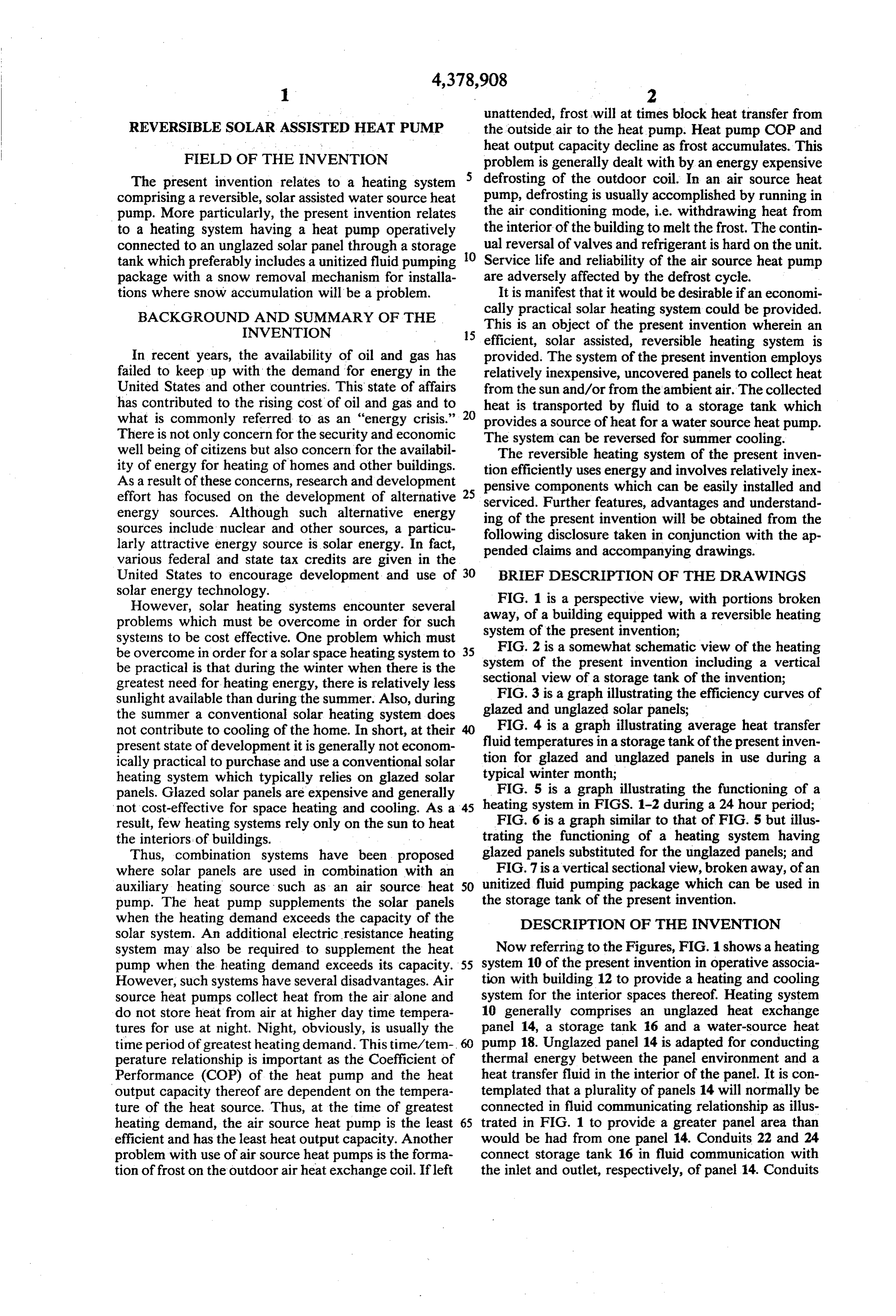
Page 6
28 and 26 connect storage tank 16 with the inlet and y=collector efficiency, EFF outlet, respectively, of heat pump 18. Heat pump 18 is a m = -FRUL which is the slope of the line water source type and is preferably reversible so that x=(Ti-T)/IT and is also called the collector param heating system 10 can be operated either to heat or cool eter.
the interior spaces of building 12. 5 b=FR(ta) which is they intersept of the line. Unglazed heat exchange panels 14 suitable for use in Equivalently, the present invention include commercially available solar heat exchange panels such as are commonly used EFF= FR(ta)-FRUL(Ti-T/IT) in solar heating systems for swimming pools. An exam ple of a panel 14 suitable for use herein is shown in U.S. 10 where
Pat. No. 3,934,323, Jan. 27, 1976, to Ford et al. As men FR =efficiency factor tioned above, it is contemplated that a plurality of pan (ta) = transmittance-absorbance product els 14 will be connected as at 29 and 31 to provide fluid U=heat transfer coefficient, BTU/HR/FT2/'F. communication therebetween and obtain an effective Ti=fluid inlet temperature, F. larger panel area than would be provided by a sole 15 Ta=ambient temperature, F.
panel 14. Suitable panels 14 commonly have an inlet IT-incident solar radiation, BTU/HR/FT2 pipe 33 and an outlet or header pipe 35 with a plurality The positive, unshaded quadrant of the graph of FIG. 3 of smaller tubes 30 extending in fluid communication is a plot of several efficiency curves defined in the con ventional manner. Extension of these curves into the therebetween.
It is important that the heat exchange panels 14 be of 20 shaded quadrants of the graph is not part of the defini the unglazed type. Panels suitable for use in the present tion of unglazed collector. The significance of these invention should have a large wetted surface area and shaded regions is discussed hereinafter in the operation be well adapted for conducting thermal energy between of the present invention.
the panel environment and heat transfer fluid in the The y intercept of the efficiency curve, b=FR (ta), interior of the panel. Such panels are employed in the 25 for a particular collector indicates the fraction of short present invention for the purpose of collecting heat wave, incident solar radition, IT, that is transferred as from, or releasing heat to, the air in addition to collect heat to the collector fluid FR for a particular solar col ing heat from direct and diffuse solar radiation. Thus, lector depends on the spacing of fluid passage ways, the glazed panels such as have a glass or other transparent heat conductivity of material between the absorber cover thereover which transmits short wave (sun) radi-30 and surface and fluid, the fluid properties, fluid flow rate, ation but does not significantly transmit long wave UL which varies with wind speed and sky tempera (thermal) radiation do not obtain the advantages of the ture. (ta) depends on short wave radiation absorbance of the absorber surface and the transmittance and absor present invention and are not suitable for use herein.
Panels comprising plastic material are preferred for bance of short wave radiation of any collector glazings. the following reasons. Plastic panels are inexpensive, 35 FR (ta) is affected somewhat by conduction, convec light and easily handled, and are durable and highly tion, or long wave radiation of heat from the top and resistant to corrosion from weather and corrosive heat underside of the absorber plate to the ambient air. The slope of the efficiency curve, m, is - FRUL, for transfer fluids. Less preferably, metal panels can be used a particular herein. Suitable metal panels include panels made of collector depends primarily on the transfer blown metal sheets such as are known in the art. Corro- 0 of heat between the collector fluid at inlet temperature, sion resistant metals such as stainless steel, bronze, Ti and the ambient air at temperature Ta. The -FRUL brass, and cupro-nickel are operable in the present in term is not significantly affected by the collector's long vention but are expensive. Steel is less expensive but wave transmittance or absorbance properties. The requires a treated brine to avoid corrosion. However, ature. -FRUL term is affected by wind speed and sky temper metal panels have an advantage in structural strength. 5 Effects of wind speed and sky temperature are The unglazed panels should be designed to provide a not significant for glazed collectors. For unglazed col reasonably low pressure drop at the required flow rate lectors, wind speed and sky temperature do signifi of 6 gallons per minute per square foot of exposed panel cantly affect the -FRUL term. Thus, the slope of the area. Panel area is sized to accommodate heat load efficiency curve, -FRUL, which is indicative of the requirements or mounting area restraints. Although, 50 ambient rate of heat transfer between the collector fluid and generally, an unglazed panel can be considered to be a air, decreases significantly as wind speed in creases and panel, sometimes referred to as a solar collector, having perature decreases. -FRUL decreases significantly as sky ten no transparent cover spaced from the surface of the panel intended to absorb sun radiation, a more mathe ofIttheis possible to define an unglazed collector in terms matical definition can be provided. Unglazed panels, or ciency slope, -FRUL, and intercept FR(ta) of its effi curve. The unglazed panel shown in U.S. Pat.
collectors, can be defined in terms of solar panel effi ciency curves. The American Society of Heating Re No. 3,034,323 which issued Jan. 27, 1976, to Ford et al. frigeration and Air Conditioning Engineers, ASHRAE, has an FR(ta) of between 0.78 and 0.85 depending on defines the solar efficiency curve in ASHRAE Standard wind speed and sky temperature. The -FRUL term for 93-77. The solar collector efficiency curve in this disclo- 60 the Ford et al. panel varies between -16 and -1.7 sure is consistent with the conventional definition in corresponds to zeroThe
wind speed and a sky temperature
ASHRAE Standard 93-77.
Collector efficiency is defined by a linear equation of close to the panel fluid temperature. However, panel the form with -FRUL less than or equal to -1.3 65 BTU/HR/Ft2/F. will result in significant advantages when used in the present invention as a collector of heat from the air and/or sun. Therefore, as used herein, an where unglazed panel is defined as a solar collector with
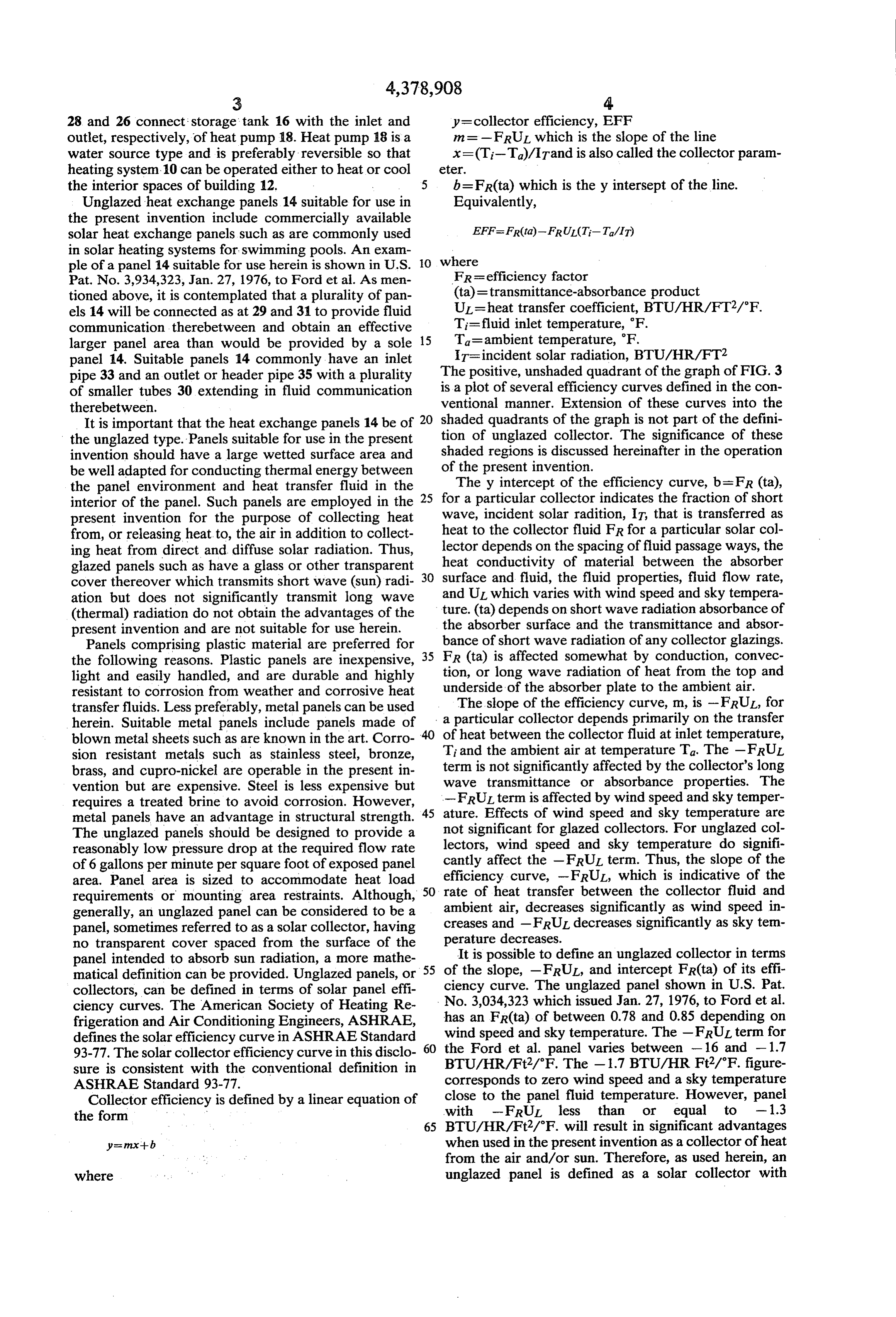
Page 7
FR(ta) of less than about 0.85 and greater than about fluid other than water if the density and heat capacity of 0.75 and FRUL of less than about - 1.3 the fluid are known.
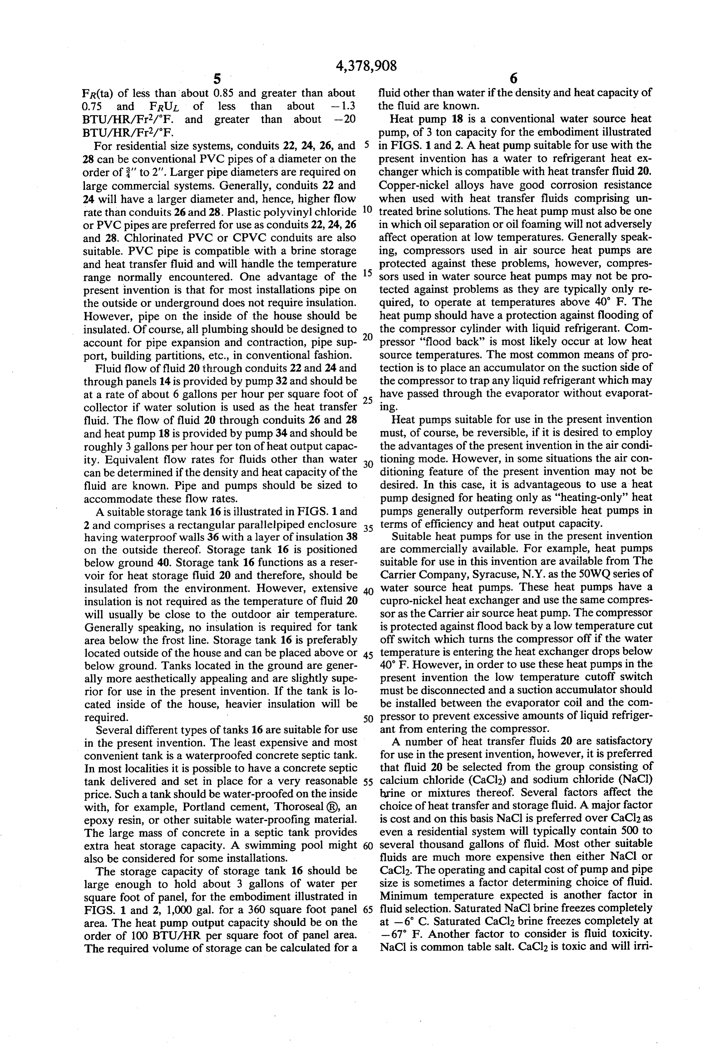
BTU/HR/Fr2/F. and greater than about -20 Heat pump 18 is a conventional water source heat BTU/HR/Fr2/'F. pump, of 3 ton capacity for the embodiment illustrated For residential size systems, conduits 22, 24, 26, and in FIGS. 1 and 2. A heat pump suitable for use with the 28 can be conventional PVC pipes of a diameter on the present invention has a water to refrigerant heat ex order of ' to 2". Larger pipe diameters are required on changer which is compatible with heat transfer fluid 20. large commercial systems. Generally, conduits 22 and Copper-nickel alloys have good corrosion resistance 24 will have a larger diameter and, hence, higher flow 10 when used with heat transfer fluids comprising un rate than conduits 26 and 28. Plastic polyvinyl chloride treated brine solutions. The heat pump must also be one or PVC pipes are preferred for use as conduits 22, 24, 26 in which oil separation or oil foaming will not adversely and 28. Chlorinated PVC or CPVC conduits are also affect operation at low temperatures. Generally speak suitable. PVC pipe is compatible with a brine storage ing, compressors used in air source heat pumps are and heat transfer fluid and will handle the temperature 15 protected against these problems, however, compres range normally encountered. One advantage of the sors used in water source heat pumps may not be pro present invention is that for most installations pipe on tected against problems as they are typically only re the outside or underground does not require insulation. quired, to operate at temperatures above 40' F. The However, pipe on the inside of the house should be heat pump should have a protection against flooding of insulated. Of course, all plumbing should be designed to 20 the compressor cylinder with liquid refrigerant. Com account for pipe expansion and contraction, pipe sup pressor "flood back' is most likely occur at low heat port, building partitions, etc., in conventional fashion. source temperatures. The most common means of pro Fluid flow of fluid 20 through conduits 22 and 24 and tection is to place an accumulator on the suction side of through panels 14 is provided by pump 32 and should be the compressor to trap any liquid refrigerant which may at a rate of about 6 gallons per hour per square foot of 25 have passed through the evaporator without evaporat collector if water solution is used as the heat transfer ling.
fluid. The flow of fluid 20 through conduits 26 and 28 Heat pumps suitable for use in the present invention and heat pump 18 is provided by pump 34 and should be must, of course, be reversible, if it is desired to employ roughly 3 gallons per hour per ton of heat output capac the advantages of the present invention in the air condi ity. Equivalent flow rates for fluids other than water 30 tioning mode. However, in some situations the air con can be determined if the density and heat capacity of the ditioning feature of the present invention may not be fluid are known. Pipe and pumps should be sized to desired. In this case, it is advantageous to use a heat accommodate these flow rates. pump designed for heating only as "heating-only' heat A suitable storage tank 16 is illustrated in FIGS. 1 and pumps generally outperform reversible heat pumps in 2 and comprises a rectangular parallelpiped enclosure 35 terms of efficiency and heat output capacity. having waterproof walls 36 with a layer of insulation 38 Suitable heat pumps for use in the present invention on the outside thereof. Storage tank 16 is positioned are commercially available. For example, heat pumps below ground 40. Storage tank 16 functions as a reser suitable for use in this invention are available from The voir for heat storage fluid 20 and therefore, should be Carrier Company, Syracuse, N.Y. as the 50WQ series of insulated from the environment. However, extensive water source heat pumps. These heat pumps have a insulation is not required as the temperature of fluid 20 cupro-nickel heat exchanger and use the same compres will usually be close to the outdoor air temperature. sor as the Carrier air source heat pump. The compressor Generally speaking, no insulation is required for tank is protected against flood back by a low temperature cut area below the frost line. Storage tank 16 is preferably off switch which turns the compressor off if the water located outside of the house and can be placed above or 45 temperature is entering the heat exchanger drops below below ground. Tanks located in the ground are gener 40' F. However, in order to use these heat pumps in the ally more aesthetically appealing and are slightly supe present invention the low temperature cutoff switch rior for use in the present invention. If the tank is lo must be disconnected and a suction accumulator should cated inside of the house, heavier insulation will be be installed between the evaporator coil and the com required. 50 pressor to prevent excessive amounts of liquid refriger Several different types of tanks 16 are suitable for use ant from entering the compressor. in the present invention. The least expensive and most A number of heat transfer fluids 20 are satisfactory convenient tank is a waterproofed concrete septic tank. for use in the present invention, however, it is preferred In most localities it is possible to have a concrete septic that fluid 20 be selected from the group consisting of tank delivered and set in place for a very reasonable 55 calcium chloride (CaCl2) and sodium chloride (NaCl) price. Such a tank should be water-proofed on the inside brine or mixtures thereof. Several factors affect the with, for example, Portland cement, Thoroseal (R), an choice of heat transfer and storage fluid. A major factor epoxy resin, or other suitable water-proofing material. is cost and on this basis NaCl is preferred over CaCl2 as The large mass of concrete in a septic tank provides even a residential system will typically contain 500 to extra heat storage capacity. A swimming pool might several thousand gallons of fluid. Most other suitable also be considered for some installations. fluids are much more expensive then either NaCl or The storage capacity of storage tank 16 should be CaCl2. The operating and capital cost of pump and pipe large enough to hold about 3 gallons of water per size is sometimes a factor determining choice of fluid. square foot of panel, for the embodiment illustrated in Minimum temperature expected is another factor in FIGS. 1 and 2, 1,000 gal. for a 360 square foot panel 65 fluid selection. Saturated NaCl brine freezes completely area. The heat pump output capacity should be on the at -6 C. Saturated CaCl2 brine freezes completely at order of 100 BTU/HR per square foot of panel area. -67 F. Another factor to consider is fluid toxicity. The required volume of storage can be calculated for a NaCl is common table salt. CaCl2 is toxic and will irri
Page 8
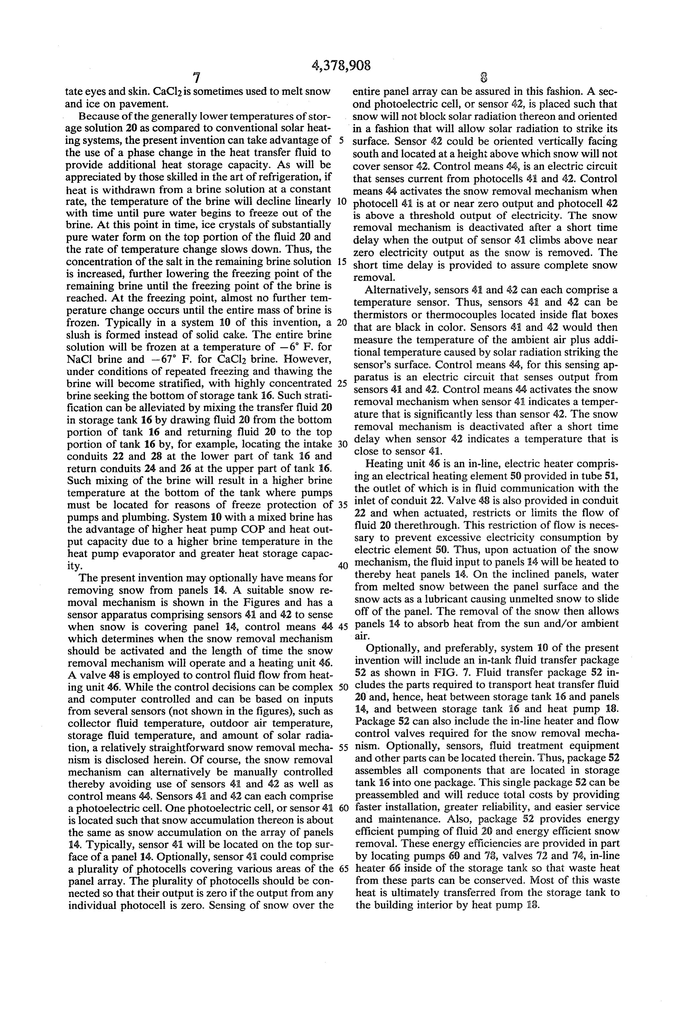
7 S tate eyes and skin. CaCl2 is sometimes used to melt snow entire panel array can be assured in this fashion. A sec and ice on pavement. ond photoelectric cell, or sensor 42, is placed such that Because of the generally lower temperatures of stor snow will not block solar radiation thereon and oriented age solution 20 as compared to conventional Solar heat in a fashion that will allow solar radiation to strike its ing systems, the present invention can take advantage of 5 surface. Sensor 42 could be oriented vertically facing the use of a phase change in the heat transfer fluid to south and located at a height above which snow will not provide additional heat storage capacity. As will be cover sensor 42. Control means 44, is an electric circuit appreciated by those skilled in the art of refrigeration, if that senses current from photocells 4 and 42. Control heat is withdrawn from a brine Solution at a constant means 44 activates the snow removal mechanism when rate, the temperature of the brine will decline linearly 10 photocell 41 is at or near zero output and photocell 42 with time until pure water begins to freeze out of the is above a threshold output of electricity. The snow brine. At this point in time, ice crystals of substantially removal mechanism is deactivated after a short time pure water form on the top portion of the fluid 20 and delay when the output of sensor 43 climbs above near the rate of temperature change slows down. Thus, the zero electricity output as the snow is removed. The concentration of the salt in the remaining brine solution 15 short time delay is provided to assure complete snow is increased, further lowering the freezing point of the removal.
remaining brine until the freezing point of the brine is Alternatively, sensors 41 and 42 can each comprise a reached. At the freezing point, almost no further tem temperature sensor. Thus, sensors 45 and 42 can be perature change occurs until the entire mass of brine is thermistors or thermocouples located inside flat boxes frozen. Typically in a system 10 of this invention, a 20 that are black in color. Sensors 48 and 42 would then slush is formed instead of solid cake. The entire brine solution will be frozen at a temperature of -6 F. for measuretional the temperature of the ambient air plus addi temperature caused by solar radiation striking the
NaCl brine and -67 F. for CaCl2 brine. However, sensor's surface. Control means 44, for this sensing ap under conditions of repeated freezing and thawing the paratus is an electric circuit that senses output from brine will become stratified, with highly concentrated 25 brine seeking the bottom of storage tank 16. Such strati sensors 41 and 42. Control means 44 activates the snow fication can be alleviated by mixing the transfer fluid 20 ature thatmechanism removal
when sensor 41 indicates a temper significantly less than sensor 42. The snow in storage tank 16 by drawing fluid 20 from the bottom removal mechanism is deactivated after a short time portion of tank 16 and returning fluid 20 to the top delay when sensor 42 indicates a temperature that is portion of tank 16 by, for example, locating the intake 30 conduits 22 and 28 at the lower part of tank 16 and close to sensor 41.
return conduits 24 and 26 at the upper part of tank 16. ingHeating unit 46 is an in-line, electric heater compris Such mixing of the brine will result in a higher brine the an electrical heating element 50 provided in tube 51, outlet of which is in fluid communication with the temperature at the bottom of the tank where pumps must be located for reasons of freeze protection of 22 and 35 inlet of conduit 22. Valve 48 is also provided in conduit pumps and plumbing. System 10 with a mixed brine has when actuated, restricts or limits the flow of the advantage of higher heat pump COP and heat out sary fluid 20 therethrough. This restriction of flow is neces put capacity due to a higher brine temperature in the to prevent excessive electricity consumption by heat pump evaporator and greater heat storage capac electric element 50. Thus, upon actuation of the snow ity. mechanism, the fluid input to panels 14 will be heated to The present invention may optionally have means for thereby heat panels 14. On the inclined panels, water removing snow from panels 14. A suitable snow re from melted snow between the panel surface and the moval mechanism is shown in the Figures and has a snow acts as a lubricant causing unmelted snow to slide sensor apparatus comprising sensors 4 and 42 to sense off of the panel. The removal of the snow then allows when snow is covering panel 14, control means 44 45 a. panels 14 to absorb heat from the sun and/or ambient which determines when the snow removal mechanism should be activated and the length of time the snow Optionally, and preferably, system 10 of the present removal mechanism will operate and a heating unit 46. invention will include an in-tank fluid transfer package A valve 48 is employed to control fluid flow from heat 52 as shown in FIG. 7. Fluid transfer package 52 in ing unit 46. While the control decisions can be complex 50 cludes the parts required to transport heat transfer fluid and computer controlled and can be based on inputs 20 and, hence, heat between storage tank 6 and panels from several sensors (not shown in the figures), such as 14, and between storage tank 16 and heat pump 8. collector fluid temperature, outdoor air temperature, Package 52 can also include the in-line heater and flow storage fluid temperature, and amount of solar radia control valves required for the snow removal mecha tion, a relatively straightforward snow removal mecha 55 nism. Optionally, sensors, fluid treatment equipment nism is disclosed herein. Of course, the snow removal and other parts can be located therein. Thus, package 52 mechanism can alternatively be manually controlled assembles all components that are located in storage thereby avoiding use of sensors 41 and 42 as well as tank 16 into one package. This single package 52 can be control means 44. Sensors 41 and 42 can each comprise preassembled and will reduce total costs by providing a photoelectric cell. One photoelectric cell, or sensor 41 60 faster installation, greater reliability, and easier service is located such that snow accumulation thereon is about and maintenance. Also, package 52 provides energy the same as snow accumulation on the array of panels efficient pumping of fluid 20 and energy efficient snow 14. Typically, sensor 41 will be located on the top sur removal. These energy efficiencies are provided in part face of a panel 14. Optionally, sensor 41 could comprise by locating pumps 60 and 78, valves 72 and 74, in-line a plurality of photocells covering various areas of the 65 heater 66 inside of the storage tank so that waste heat panel array. The plurality of photocells should be con from these parts can be conserved. Most of this waste nected so that their output is zero if the output from any heat is ultimately transferred from the storage tank to individual photocell is zero. Sensing of snow over the the building interior by heat pump 18.
Page 9
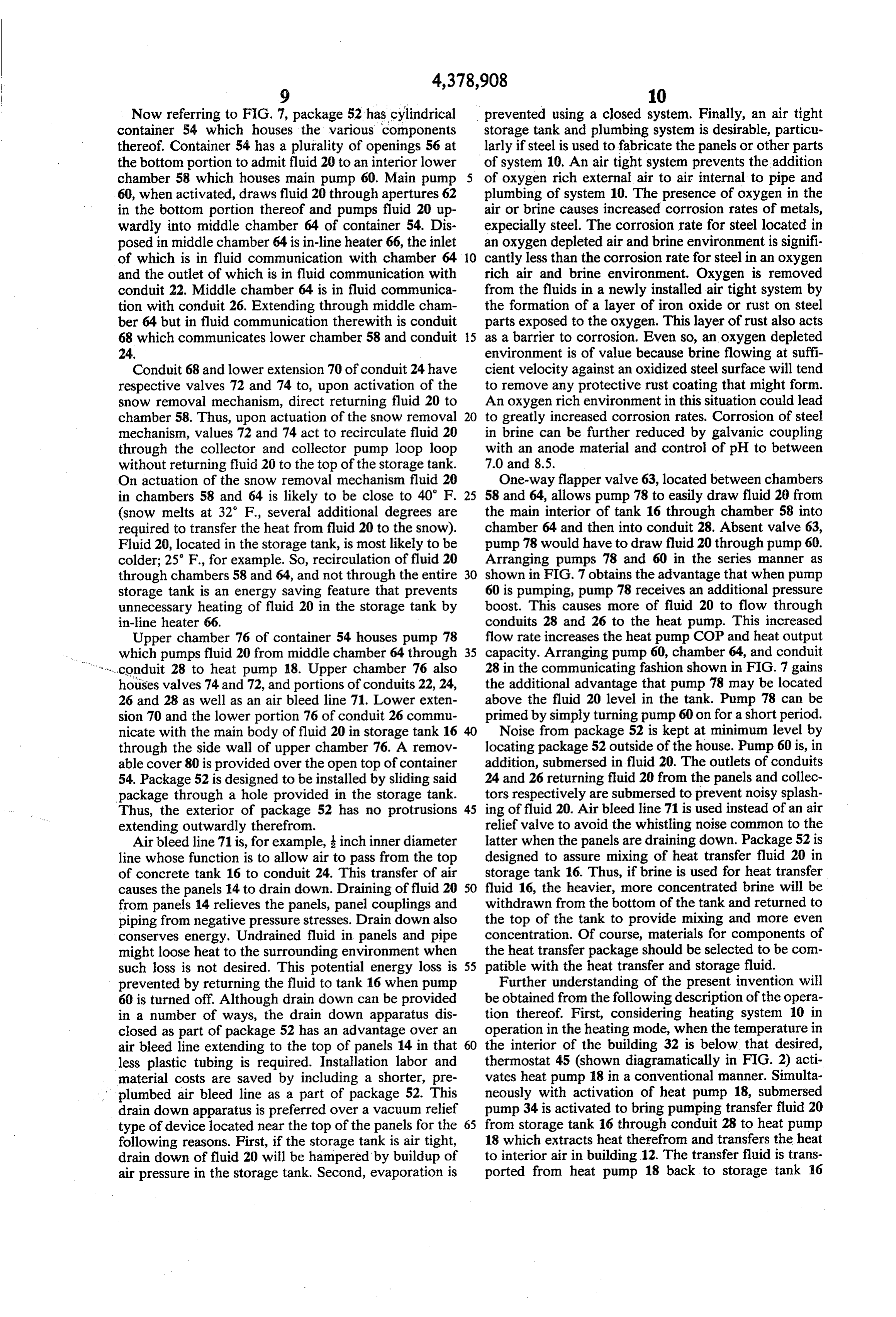
Now referring to FIG. 7, package 52 has cylindrical prevented using a closed system. Finally, an air tight container 54 which houses the various components storage tank and plumbing system is desirable, particu thereof. Container 54 has a plurality of openings 56 at larly if steel is used to fabricate the panels or other parts the bottom portion to admit fluid 20 to an interior lower of system 10. An air tight system prevents the addition chamber 58 which houses main pump 60. Main pump of oxygen rich external air to air internal to pipe and 60, when activated, draws fluid 20 through apertures 62 plumbing of system 10. The presence of oxygen in the in the bottom portion thereof and pumps fluid 20 up air or brine causes increased corrosion rates of metals, wardly into middle chamber 64 of container 54. Dis expecially steel. The corrosion rate for steel located in posed in middle chamber 64 is in-line heater 66, the inlet an oxygen depleted air and brine environment is signifi of which is in fluid communication with chamber 64 10 cantly less than the corrosion rate for steel in an oxygen and the outlet of which is in fluid communication with rich air and brine environment. Oxygen is removed conduit 22. Middle chamber 64 is in fluid communica from the fluids in a newly installed air tight system by tion with conduit 26. Extending through middle cham the formation of a layer of iron oxide or rust on steel ber 64 but in fluid communication therewith is conduit parts exposed to the oxygen. This layer of rust also acts 68 which communicates lower chamber 58 and conduit 5 as a barrier to corrosion. Even so, an oxygen depleted 24. environment is of value because brine flowing at suffi Conduit 68 and lower extension 70 of conduit 24 have cient velocity against an oxidized steel surface will tend respective valves 72 and 74 to, upon activation of the to remove any protective rust coating that might form. snow removal mechanism, direct returning fluid 20 to An oxygen rich environment in this situation could lead chamber 58. Thus, upon actuation of the snow removal 20 to greatly increased corrosion rates. Corrosion of steel mechanism, values 72 and 74 act to recirculate fluid 20 in brine can be further reduced by galvanic coupling through the collector and collector pump loop loop with an anode material and control of pH to between without returning fluid 20 to the top of the storage tank. 7.0 and 8.5.
On actuation of the snow removal mechanism fluid 20 One-way flapper valve 63, located between chambers in chambers 58 and 64 is likely to be close to 40 F. 25 58 and 64, allows pump 78 to easily draw fluid 20 from (snow melts at 32” F., several additional degrees are the main interior of tank 16 through chamber 58 into required to transfer the heat from fluid 20 to the snow). chamber 64 and then into conduit 28. Absent valve 63, Fluid 20, located in the storage tank, is most likely to be pump 78 would have to draw fluid 20 through pump 60. colder; 25 F., for example. So, recirculation of fluid 20 Arranging pumps 78 and 60 in the series manner as through chambers 58 and 64, and not through the entire 30 shown in FIG. 7 obtains the advantage that when pump storage tank is an energy saving feature that prevents 60 is pumping, pump 78 receives an additional pressure unnecessary heating of fluid 20 in the storage tank by boost. This causes more of fluid 20 to flow through in-line heater 66. conduits 28 and 26 to the heat pump. This increased Upper chamber 76 of container 54 houses pump 78 flow rate increases the heat pump COP and heat output which pumps fluid 20 from middle chamber 64 through 35 capacity. Arranging pump 60, chamber 64, and conduit conduit 28 to heat pump 18. Upper chamber 76 also 28 in the communicating fashion shown in FIG. 7 gains houses valves 74 and 72, and portions of conduits 22, 24, the additional advantage that pump 78 may be located 26 and 28 as well as an air bleed line 71. Lower exten above the fluid 20 level in the tank. Pump 78 can be sion 70 and the lower portion 76 of conduit 26 commu primed by simply turning pump 60 on for a short period. nicate with the main body of fluid 20 in storage tank 16 Noise from package 52 is kept at minimum level by through the side wall of upper chamber 76. A remov locating package 52 outside of the house. Pump 60 is, in able cover 80 is provided over the open top of container addition, submersed in fluid 20. The outlets of conduits 54. Package 52 is designed to be installed by sliding said 24 and 26 returning fluid 20 from the panels and collec package through a hole provided in the storage tank. tors respectively are submersed to prevent noisy splash Thus, the exterior of package 52 has no protrusions 45 ing of fluid 20. Air bleed line 71 is used instead of an air extending outwardly therefrom. relief valve to avoid the whistling noise common to the Air bleed line 71 is, for example, inch inner diameter latter when the panels are draining down. Package 52 is line whose function is to allow air to pass from the top designed to assure mixing of heat transfer fluid 20 in of concrete tank 16 to conduit 24. This transfer of air storage tank 16. Thus, if brine is used for heat transfer causes the panels 14 to drain down. Draining of fluid 20 50 fluid 16, the heavier, more concentrated brine will be from panels 14 relieves the panels, panel couplings and withdrawn from the bottom of the tank and returned to piping from negative pressure stresses. Drain down also the top of the tank to provide mixing and more even conserves energy. Undrained fluid in panels and pipe concentration. Of course, materials for components of might loose heat to the surrounding environment when the heat transfer package should be selected to be com such loss is not desired. This potential energy loss is 55 patible with the heat transfer and storage fluid. prevented by returning the fluid to tank 16 when pump Further understanding of the present invention will 60 is turned off. Although drain down can be provided be obtained from the following description of the opera in a number of ways, the drain down apparatus dis tion thereof. First, considering heating system 10 in closed as part of package 52 has an advantage over an operation in the heating mode, when the temperature in air bleed line extending to the top of panels 14 in that 60 the interior of the building 32 is below that desired, less plastic tubing is required. Installation labor and thermostat 45 (shown diagramatically in FIG. 2) acti material costs are saved by including a shorter, pre vates heat pump 18 in a conventional manner. Simulta plumbed air bleed line as a part of package 52. This neously with activation of heat pump 18, submersed drain down apparatus is preferred over a vacuum relief pump 34 is activated to bring pumping transfer fluid 20 type of device located near the top of the panels for the 65 from storage tank 16 through conduit 28 to heat pump following reasons. First, if the storage tank is air tight, 18 which extracts heat therefrom and transfers the heat drain down of fluid 20 will be hampered by buildup of to interior air in building 12. The transfer fluid is trans air pressure in the storage tank. Second, evaporation is ported from heat pump 18 back to storage tank 16
Page 10
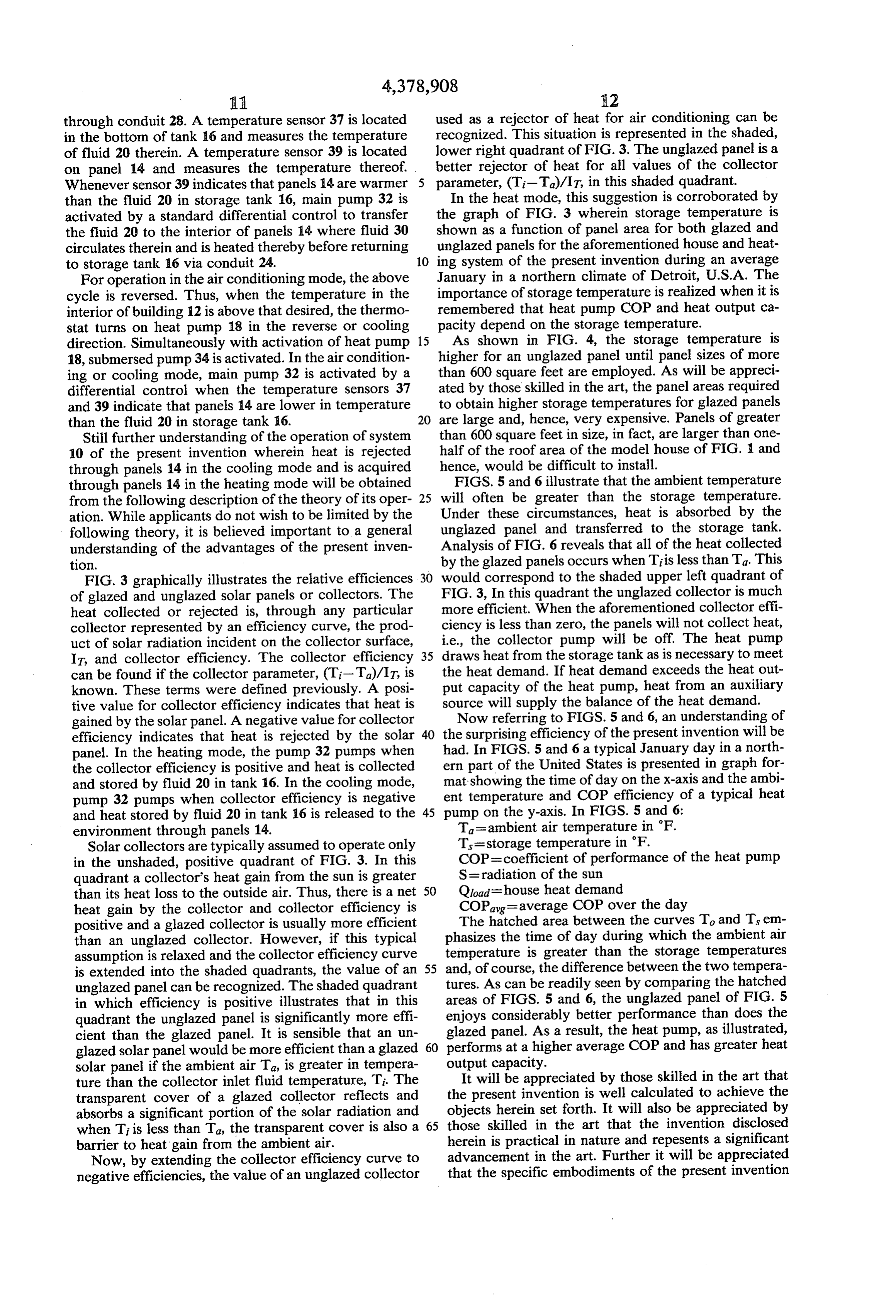
through conduit 28. A temperature sensor 37 is located used as a rejector of heat for air conditioning can be in the bottom of tank 16 and measures the temperature recognized. This situation is represented in the shaded, of fluid 20 therein. A temperature sensor 39 is located lower right quadrant of FIG. 3. The unglazed panel is a on panel 14 and measures the temperature thereof. better rejector of heat for all values of the collector Whenever sensor 39 indicates that panels 14 are warmer parameter, (T-T)/IT, in this shaded quadrant. than the fluid 20 in storage tank 16, main pump 32 is In the heat mode, this suggestion is corroborated by activated by a standard differential control to transfer the graph of FIG. 3 wherein storage temperature is the fluid 20 to the interior of panels 14 where fluid 30 shown as a function of panel area for both glazed and circulates therein and is heated thereby before returning unglazed panels for the aforementioned house and heat to storage tank 16 via conduit 24. 10 ing system of the present invention during an average For operation in the air conditioning mode, the above January in a northern climate of Detroit, U.S.A. The cycle is reversed. Thus, when the temperature in the importance of storage temperature is realized when it is interior of building 12 is above that desired, the thermo remembered that heat pump COP and heat output ca stat turns on heat pump 18 in the reverse or cooling pacity depend on the storage temperature. direction. Simultaneously with activation of heat pump 15 As shown in FIG. 4, the storage temperature is 18, submersed pump 34 is activated. In the air condition higher for an unglazed panel until panel sizes of more ing or cooling mode, main pump 32 is activated by a than 600 square feet are employed. As will be appreci differential control when the temperature sensors 37 ated by those skilled in the art, the panel areas required and 39 indicate that panels 14 are lower in temperature to obtain higher storage temperatures for glazed panels than the fluid 20 in storage tank 16. 20 are large and, hence, very expensive. Panels of greater Still further understanding of the operation of system than 600 square feet in size, in fact, are larger than one 10 of the present invention wherein heat is rejected half of the roof area of the model house of FIG. 1 and through panels 14 in the cooling mode and is acquired hence, would be difficult to install. through panels 14 in the heating mode will be obtained FIGS. 5 and 6 illustrate that the ambient temperature from the following description of the theory of its oper 25 will often be greater than the storage temperature. ation. While applicants do not wish to be limited by the Under these circumstances, heat is absorbed by the following theory, it is believed important to a general unglazed panel and transferred to the storage tank. understanding of the advantages of the present inven Analysis of FIG. 6 reveals that all of the heat collected tion. by the glazed panels occurs when Tiis less than Ta. This FIG. 3 graphically illustrates the relative efficiences 30 would correspond to the shaded upper left quadrant of of glazed and unglazed solar panels or collectors. The FIG. 3, In this quadrant the unglazed collector is much heat collected or rejected is, through any particular more efficient. When the aforementioned collector effi collector represented by an efficiency curve, the prod ciency is less than zero, the panels will not collect heat, uct of solar radiation incident on the collector surface, i.e., the collector pump will be off. The heat pump IT, and collector efficiency. The collector efficiency 35 draws heat from the storage tank as is necessary to meet can be found if the collector parameter, (T-T)/IT, is the heat demand. If heat demand exceeds the heat out known. These terms were defined previously. A posi put capacity of the heat pump, heat from an auxiliary tive value for collector efficiency indicates that heat is source will supply the balance of the heat demand. gained by the solar panel. A negative value for collector Now referring to FIGS. 5 and 6, an understanding of efficiency indicates that heat is rejected by the solar 40 the surprising efficiency of the present invention will be panel. In the heating mode, the pump 32 pumps when had. In FIGS. 5 and 6 a typical January day in a north the collector efficiency is positive and heat is collected ern part of the United States is presented in graph for and stored by fluid 20 in tank 16. In the cooling mode, mat showing the time of day on the x-axis and the ambi pump 32 pumps when collector efficiency is negative ent temperature and COP efficiency of a typical heat and heat stored by fluid 20 in tank 16 is released to the 45 pump on the y-axis. In FIGS. 5 and 6: environment through panels 14. Ta=ambient air temperature in F. Solar collectors are typically assumed to operate only T=storage temperature in F. in the unshaded, positive quadrant of FIG. 3. In this COP=coefficient of performance of the heat pump quadrant a collector's heat gain from the sun is greater S= radiation of the sun than its heat loss to the outside air. Thus, there is a net 50 Qload=house heat demand heat gain by the collector and collector efficiency is COPag=average COP over the day positive and a glazed collector is usually more efficient The hatched area between the curves To and Ts em than an unglazed collector. However, if this typical phasizes the time of day during which the ambient air assumption is relaxed and the collector efficiency curve temperature is greater than the storage temperatures is extended into the shaded quadrants, the value of an 55 and, of course, the difference between the two tempera unglazed panel can be recognized. The shaded quadrant tures. As can be readily seen by comparing the hatched in which efficiency is positive illustrates that in this areas of FIGS. 5 and 6, the unglazed panel of FIG. 5 quadrant the unglazed panel is significantly more effi enjoys considerably better performance than does the cient than the glazed panel. It is sensible that an un glazed panel. As a result, the heat pump, as illustrated, glazed solar panel would be more efficient than a glazed 60 performs at a higher average COP and has greater heat solar panel if the ambient air Ta, is greater in tempera output capacity.
ture than the collector inlet fluid temperature, Ti. The It will be appreciated by those skilled in the art that transparent cover of a glazed collector reflects and the present invention is well calculated to achieve the absorbs a significant portion of the solar radiation and thoseobjects herein set forth. It will also be appreciated by when Ti is less than Ta, the transparent cover is also a 65 herein skilled
in the art that the invention disclosed practical in nature and repesents a significant barrier to heat gain from the ambient air.
Now, by extending the collector efficiency curve to advancement in the art. Further it will be appreciated negative efficiencies, the value of an unglazed collector that the specific embodiments of the present invention
Page 11
disclosed herein are subject to modification, variation therein for selectively effecting the transfer of fluid into and change without departing from the spirit of the said middle chamber under pressure and wherein said present invention. middle chamber is connected to a conduit communicat What is claimed is: ing with said panel and to a conduit communicating 1. In a solar assisted heating system comprising at with said heat pump.
least one solar collector panel, connected in fluid con 3. The system as recited in claim 1 including a heat munication with a storage tank by conduit means, a transfer package positioned in said storage tank, said snow removal mechanism for removing snow from said package comprising a container having a lower cham panel, said snow removal mechanism comprising an ber, a middle chamber, and an upper chamber, and in-line heating element positioned in said conduit means O wherein said lower chamber has a main pump therein providing fluid communication from said storage tank for selectively effecting the transfer of fluid into said to said panel, means for transporting a heat transfer fluid middle chamber under pressure and wherein said mid at a less than normal flow rate through said heating dle chamber is connected to a conduit communicating element to said panel, and means for actuating said with said panel and to a conduit communicating with heating element, said heating system further comprising 15 sensing means for sensing snow on said panel and auto said4. heatThe pump.
system as recited in claim 3 wherein a second matic control means for actuating said heater in re sponse to said sensing means sensing snow on said panel, pump is positioned in said conduit communicating with said sensing means comprising a first sensor positioned said heat pump.
on said panel and facing in parallel relationship there 20 5. A solar assisted heating system as recited in claim with and a second sensor positioned proximate to said 1 wherein each of said first and second sensors are pho panel and facing generally horizontally. toelectric sensors.
2. In a solar assisted heating system comprising at 6. A solar assisted heating system as recited in claim least one solar collector panel in fluid communication 1 wherein each of said first and second sensors is a with a storage tank in fluid communication with a heat 25 temperature sensor.
pump, a heat transfer package located in said storage 7. In a solar assisted heating system as recited in claim tank, said package comprising a container having a 2, wherein a second pump is positioned in said conduit lower chamber, a middle chamber, and an upper cham communicating with said heat pump. k ber, and wherein said lower chamber has a main pump
Provenance
- Collection
- Cited prior art
- Original PDF
- patentimages.storage.googleapis.com →
- Filed
- 1979-12-10
- Pages
- 11
- Method
- pdftotext (the PDF's own text layer) + pdftoppm 300dpi page scans
- Source
- Google Patents bibliographic record
- Granted
- 1983-04-05
- Inventors
- Robert A. Wood
- Transcribed from
- patentimages.storage.googleapis.com →