patent · US4010731
Heat storage tank
8 March 1977
Page 1 — bibliographic record
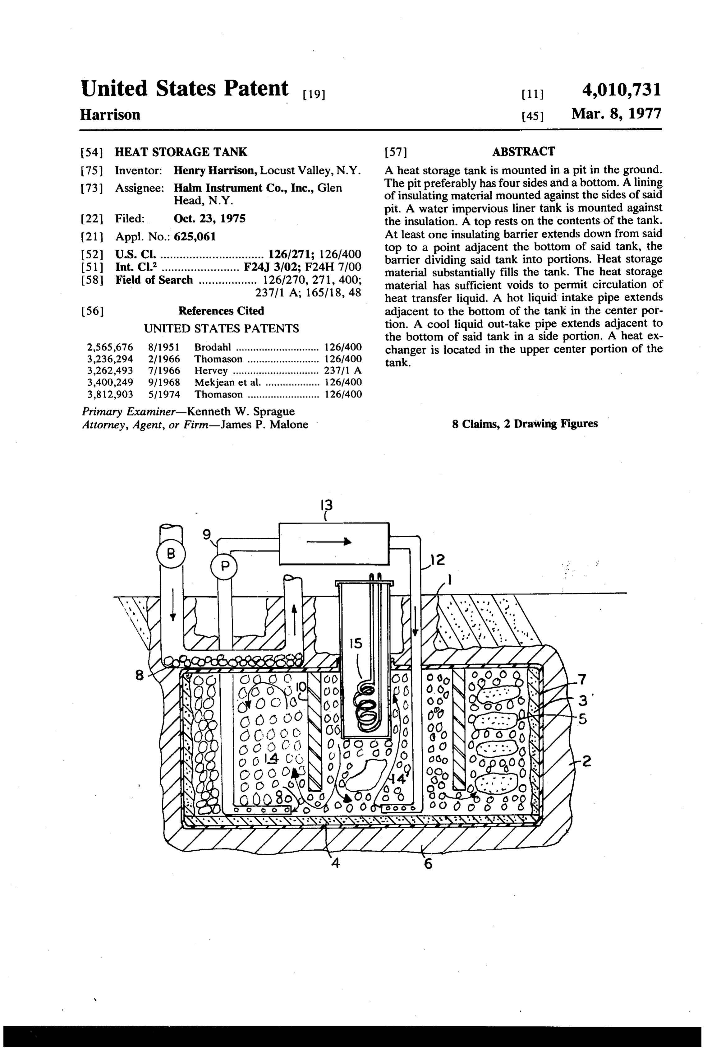
United States Patent to 11, 4,010,731 Harrison 45 Mar. 8, 1977 54 HEAT STORAGE TANK 57 ABSTRACT 75 Inventor: Henry Harrison, Locust Valley, N.Y. A heat storage tank is mounted in a pit in the ground. 73) Assignee: Halm Instrument Co., Inc., Glen The pit preferably has four sides and a bottom. A lining Head, N.Y. uv. Irvy of insulating material mounted against the sides of said y s pit. A water impervious liner tank is mounted against 22 Filed: Oct. 23, 1975 the insulation. A top rests on the contents of the tank. 21 Appl. No.: 625,061 At least one insulating barrier extends down from said s top to a point adjacent the bottom of said tank, the
E. ES aF83.48 barrier dividing said tank into portions. Heat storage 58 Field of search a a - as as - d - - - - a 126270 27, 400 material substantially fills the tank. The heat storage "37, A: 165/18 48 material has sufficient voids to permit circulation of s heat transfer liquid. A hot liquid intake pipe extends 56) References Cited adjacent to the bottom of the tank in the center por UNITED STATES PATENTS tion. A cool liquid out-take pipe extends adjacent to the bottom of said tank in a side portion. A heat ex i.S.S.S E. Gon a -a - a a- - - - - : changer is located in the upper center portion of the 3.262.493 7/i966 Hervey. ;: tank.
3,400,249 9/1968 Mekjean et al. ................... 126/400 3,812,903 5, 1974 Thomason ......................... 126/400
Primary Examiner-Kenneth W. Sprague
Attorney, Agent, or Firm-James P. Malone 8 Claims, 2 Drawing Figures
ggs;334 al
Page 2
Drawing sheet — no readable text.
Page 3
HEAT STORAGE TANK
tank in one of the side portions thereof, and a heat exchanger located in the upper center portion of said
This invention relates to heat storage tanks and more tank.
particularly to heat storage tank for a house. These and other objects of the invention will be ap In view of the energy shortage, there is a need for parent from the following specification and drawings, means to heating a house while conserving energy. of which:
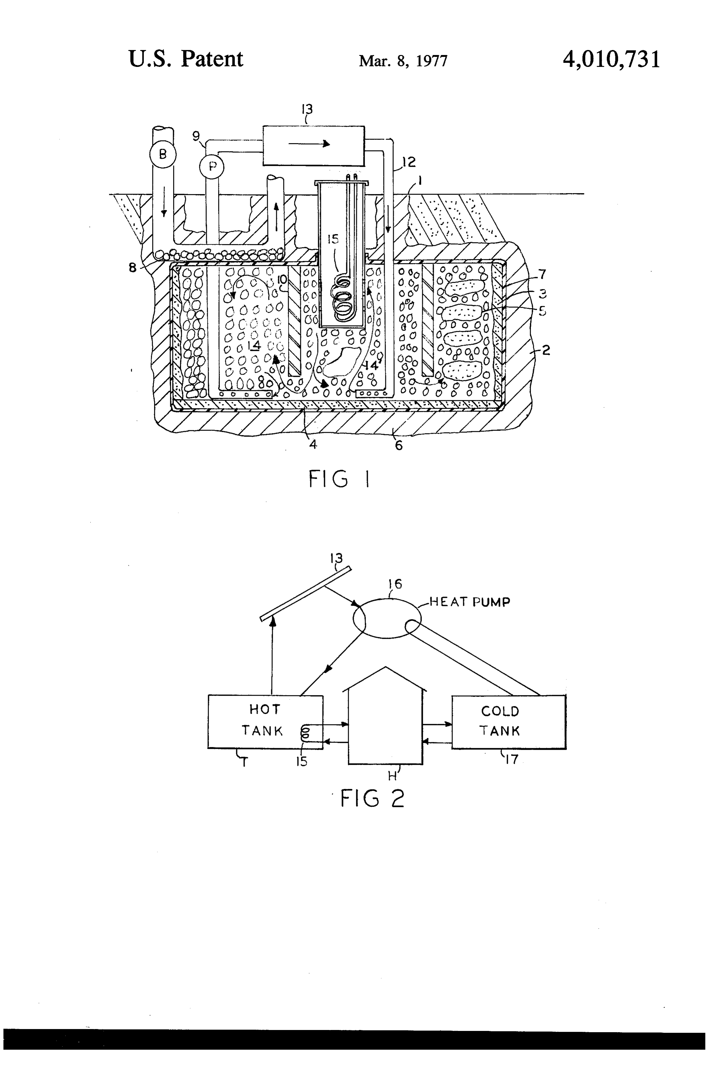
Solar energy heat collectors have been developed FIG. 1, is a side sectional view of an embodiment of which are quite efficient. However, in order to make the invention.
practical use of them, it is necessary to have some kind FIG. 2, is a schematic diagram illustrating the use of of a heat storage system to maintain the heating of the 10 the invention.
house during nights and periods of cloudy, sunless days. Referring to FIG. 1, the heat storage tank is prefer The present invention provides a heat storage tank ably mounted in a pit 1, in the ground. The sides and which is connected to a solar heat collector to provide the bottom of the pit are lined with incompressible sufficient heat storage to obtain practical use of the insulation 2, which may be a foam material of polysty solar heat collector. 15 rene or polyethylene. If the soil is dry and the bottom of The present invention provides a storage tank which the pit is at least several feet above the water table, the is sunk into the ground. An outer liner of incompress bottom portion 6 of the foam insulation may be omitted ible insulating material is provided. A water impervious as the soil itself will provide sufficient insulation. Inside liner tank is mounted against the insulation. A top rests the insulation is mounted a water impervious liner tank on the contents of the tank and the tank is divided into 20 7, which may be of plastic, for instance, of vinyl or center and side portions by at least one insulating bar polyethylene. The plastic tank liner does not have to rier extending from the tank top to a point near the have any appreciable structural strength since it is sup bottom of the tank. Hot water from the heat collector ported by the surrounding earth and the contents of the is brought into the center portion. The tank is substan tank. To prevent puncturing the liner 7 when the tank tially filled with heat storage material such as gravel 25 is being built, a layer of sand 4, a few inches thick is and stones and water. The hot water will collect and spread on the bottom. Protection for the sides may be circulate in the center portion of the tank. Domestic a layer 3 of sand, or alternatively of mastic or plastic hot water may be heated in a heat exchanger mounted foam. The top of the tank is covered by a portion of the in the upper center portion. Cooler water is pumped liner tank 7, and may have a layer of stones 8 which from a side portion to the input of the solar heat collec 30 provides an extended heat transfer surface for heating tor. Some of the heat storage material may be layers or warm air. An insulating barrier 10 extends down from pockets of finer material, such as sand. The gravel and the top, leaving only sufficient space at the bottom for stones have sufficient voids between them to provide free passage of water. The barrier 10, separates the for good heat exchange fluid circulation. The heat tank into a center portion and a side portion. exchange fluid is preferably water, but other fluid may 35 The tank is substantially filled with gravel and stones be used. The heat storage tank of the present invention 14 of reasonably uniform size so that there will be provides adequate heat storage with a minimum of sufficient void spaces between them for a good circula materials. tion of water. Finer materials which permit less water Accordingly, a principal object of the invention is to circulation may be clumped in layers or pockets 5 provide new and improved heat storage means. 40 which are surrounded by gravel. Earth taken from the Another object of the invention is to provide new and pit 1 can frequently be used for filling the tank after it improved heat storage means connected to a solar has been screened to develop water circulation voids. collector as a part of a practical heating system for a A hot water intake pipe 12, extends down to the house. bottom of the center portion of the tank. A cold water Another object of the invention is to provide new and 45 out-take pipe 9, extends from the bottom side portion improved heat storage tank requiring a minimum of up to the top of the tank. A pump P, is connected to the material and avoiding the need for any heavy structural out-take pipe to pump cool water to a heat source 13, members. which may be a solar heat collector which heats the Another object of the invention is to provide new and water. The water then flows down through the pipe 12, improved storage tank wherein the stored heated water 50 and out into the center portion of the tank as shown by is horizontally stratified according to temperature. the arrow 14'. In the center portion of the tank, the Another object of the invention is to provide a new hottest water will rise to the top where it will come in and improved heat storage tank mounted in a pit in the contact with the heat exchange device 15, which will ground, said pit having a continuous side portion and a extract the heat for the purpose of providing hot water bottom, a lining of incompressible insulating material 55 and heat to the house. The insulating barrier 10, tends mounted against said continuous side portion of said to trap the hottest water in the center portion. The pit, a water impervious liner tank having a continuous coolest water in the center portion flows under the side portion and a bottom mounted against said insulat barrier 10 into the side portion. The warmest portion of ing material, a top resting on the contents of said tank, this water rises to the top, where its heat may pass into at least one insulating barrier extending down from said 60 the heat exchange rock layer 8 by conduction, there it top to a point near the bottom of said tank, said barrier warms house-heating air circulated by blower B. dividing said tank into a center portion and at least one The tank for a well-insulated one family dwelling may side portion, heat storage material substantially filling be approximately 20 x 30 feet and about 5 feet deep. said tank, said heat storage material having sufficient This size tank stores enough heat so that heat collected voids to permit circulation of heat transfer liquid, a hot 65 in summer can be used for winter heating. liquid intake pipe extending adjacent to the bottom of For maximum economy, it may be desired to bond at said tank in the center portion thereof, a cool liquid least some of the contents of the tank together with out-take pipe extending adjacent to the bottom of said cement. This creates a porous monolithic concrete
Page 4
block with sufficient strength to serve as the foundation a lining of incompressible insulating material for a house. The house is then erected directly on top of mounted against said continuous side portion of the heat storage reservoir. said pit,
If the tank actually extends below the water table in a liquid-impervious flexible liner tank having a con the ground it would be desirable to have an additional tinuous side portion and a bottom mounted against plastic liner on the outside of the insulation. said incompressible insulating material and a top In operation, water will be heated by the solar heat portion resting on the contents of said tank, collector and pumped down to the center portion of the at least one insulating barrier extending down from said top to a point adjacent the bottom of said tank, tank where it will circulate upwardly so that the hottest O said barrier dividing said tank into at least a first place in the tank will be the upper center portion. Heat and a second portion, will be extracted from this portion by the heat ex heat storage material substantially filling said tank, changer 15, when desired. said heat storage material having sufficient voids to The present invention provides a heat storage tank of permit circulation of heat transfer liquid, simple construction which requires a minimum amount 15 a hot liquid intake pipe extending adjacent to the of materials. No structural members are under any bottom of said tank in said first portion thereof, strain. The plastic liner can be of low temperature a cool liquid out-take pipe extending adjacent to the plastic and it is not subject to any strain because it is bottom of said tank in said second portion thereof, supported by sand or gravel on both sides so that it will and means for withdrawing heat from the upper part operate without damage even to boiling water tempera 20 of said first portion of said tank. tle. 2. Apparatus as in claim 1, wherein said heat storage The high temperature water is horizontally stratified material comprises gravel and stones. - 3. Apparatus as in claim 1, wherein said heat storage since it is trapped at the top of the centerportion where material comprises gravel and stones and pockets of it is extracted by the heat exchanger. 25 finer aggregates.
FIG. 2, illustrates the use of the storage tank T, in a 4. Apparatus as in claim 1, wherein said water imper complete system. The heat storage tank T is connected vious liner tank is made of plastic sheet. to the heat collector 13, and is connected to the house 5. Apparatus as in claim 1, having a solar heat collec H, by means of heat exchanger 15. The heat pump 16, tor, the heat storage tank being connected to the solar circulates the heating water. A complete system prefer 30 heat collector.
ably has a cold storage tank 17, which is connected to 6. Apparatus as in claim 1, wherein said means for the heat pump 16, and the house H, for providing cool withdrawing immersed in heat is a liquid to liquid heat exchanger said first portion of said tank.
ing services, such as air conditioning. The cold storage tank may be as described in my co-pending application 35 drawing heat frominthe 7. Apparatus as claim 1, including means for with upper part of said second por entitled "COLD STORAGE TANK", Ser. No. 631,057 tion of said tank.
filed on Nov. 12, 1975. 8. Apparatus as in claim 2, wherein at least some of I claim: said gravel and stones is bonded together with cement, 1. A heat storage tank mounted in a pit in the ground, to create a load-bearingas porous structure. said pit having a continuous side portion and a bottom, 40 . . . . .
Provenance
- Collection
- Cited prior art
- Original PDF
- patentimages.storage.googleapis.com →
- Filed
- 1975-10-23
- Pages
- 4
- Method
- pdftotext (the PDF's own text layer) + pdftoppm 300dpi page scans
- Source
- Google Patents bibliographic record
- Granted
- 1977-03-08
- Inventors
- Henry Harrison; Halm Instrument Co Inc
- Transcribed from
- patentimages.storage.googleapis.com →