patent · US4002158
Support structure for solar energy converter
11 January 1977
Page 1 — bibliographic record
United States Patent to 11 4,002,158 Radebold 45 Jan. 11, 1977 54 SUPPORT STRUCTURE FOR SOLAR 3,489,072 1/1970 Secor .................................... 98/58 ENERGY CONVERTER 3,807,384 4/1974 Schach et al. ................. 26/270 R 76 Inventor: Reinhart Radebold,
Quastenhornweg 14a, 1 Berlin 22, Primary Examiner-John J. Camby
Germany Assistant Examiner-Henry C. Yuen
Attorney, Agent, or Firm-Ralf H. Siegemund
21 Appl. No.: 545,134 57 ABSTRACT 30) Foreign Application Priority Data A plurality of solar energy conversion units, each with Jan. 30, 1974 Germany .......................... 240534 a reflecting mirror, are disposed on top of a stem or 52 U.S. Cl. .................................. 126/270; 60/641 reed-like tower composed of a bundle of major supply (51 int. Cl”............................................ F24J 3/02 tubes each terminating in a conversion unit plus mirror 58) Field of Search ................. 126/270,271; 52/2, combination with additional tubes provided in the stem for up and down transport of gases and liquids. Particu 52/83; 60/641 larly buoyant mirror constructions and anchoring facil 56 References Cited ities for the bundle are described.
UNITED STATES PATENTS
3,220,67. 1 1/1965 Ashman et al. ................... 126/270 12 Claims, 12 Drawing Figures
Page 2
Drawing sheet — no readable text.
Page 3
Drawing sheet — no readable text.
Page 4
Drawing sheet — no readable text.
Page 5
Drawing sheet — no readable text.
Page 6
sphere, which can be found in this zone at about 11 km
SUPPORT STRUCTURE FOR SOLAR ENERGY in height. Clusters of mirrors, which can be stabilized in CONVERTER regard to height by their own buoyance forces, are, however, objected to large wind forces; a stationary
BACKGROUND OF THE INVENTION operation of transformers, and, at least the tethering of The present invention relates to the positioning of a mirrors seams to be impossible. At 20 km in height, the hydrazine generator or the like, using solar energy as situation is actually different in this zone; both climate primary source for energy, in an elevated position. and wind influences are minimal (zero layer). More particularly, the invention relates to the position 10 tionTheeven exergy transformer as such is designed for opera in this altitude (in the most unfavorable ing of a hydrazine generator constructed in accordance with my copending application Ser. No. 545,133, filed case). The radiation is focused at MHD-modules en Jan. 29, 1975. trance; the strong interactions within the MHD-proc The copending application discloses and claims a ess, especially the electro-magnetic interaction used for hydrazine generator operating on the principle of mag exergy extraction, permits operation of the module in neto-hydrodynamic conversion to synthetize hydrazine 15 high altitudes for a longer operation period due to the out of hydrogen and nitrogen under utilization of solar fact that the module is hermetically sealed in regard to energy. A high degree of efficiency, particularly on a its ambience and has no moving parts. The light weight long term basis, requires that solar energy be utilized to construction of the MHD-converter and its accessories the utmost extent possible. Placing the solar energy reduces the requirement for large buoyancing bodies, converter or transformer close to or directly on the 20 since exergy is extracted from the radiation received ground is practical only where the average of the dura and presented by the device inform of electrical energy tion of sunshine is quite high. Obviously, one will ob at high voltage and high frequency, and since a large tain best results in the desert region of median latitudes portion of this exergy is stored immediately within the or on high mountains. On the other hand, the energy module by synthesis, the exergy transformer in accor dance to this invention can be operated in a manner converter or transformer works more efficiently if the 25 that temperature differential between heating and the tem is superior to all other exergy transforming systems perature of isothermic compression of the gaseous, (such as turbo-systems, thermionic converters, solar auxiliary medium in the conversion and transformation cells), particularly in regard to reliability and the trans system as described is as high as possible. Obviously, mission of the exergy (to ground). - one will not operated at optimum conditions in the 30 The problem of anchoring an exergy transformer is desert, but will be restricted to high desert mountains. similar for any system to be operated in significant heights. The support of the exergy transformer (de
FEATURES OF THE INVENTION signed in analogy to botanical organisms) is provided to have, in addition, several different functions, such as
It is an object of the present invention to provide for the transport of cooling air, the separation of HO from a structure to position an energy converter as described 35 the cooling air, transporting H2 from ground as well as in the said copending application, in an elevated posi tion. . . . . the transport of hydrazine synthesized and electrical The energy converter and transformer is of modular, energy for the HO-electrolysis and for general power elongaged, tubular construction and is placed within supply to ground. These functions together will be the cavity defined by a parabolic mirror focusing solar 40 executed by the reed-like support or connection as radiation onto that portion of the converter provided to stated above. This support must be elastic and resilient receive radiant energy, for heating the absorbing parts to compensate the alternating wind forces, and, in addi to about 800 Kelvin. The mirror is constructed from tion, it must withstand tensile as well as compressive gas filled chambers, cushion and backing to obtain stress. The reed-like tower must be produced in a way some buoyancy. The other end of the converter is 45 a plant stem is growing from ground, lifted by the buoy cooled by air, outside of the focusing effect of the mir ancy-generating mirror system. The material used for ror. This arrangement is placed on a stalk, stem, tower construction should be light by weight but have an or "reed' extending sufficiently above the earth's sur extreme tearing length; finally the reed-like stem face and one will obtain both, a high temperature dif should have transportation channels for the personnel ferential and little or no interruption of sunshine in the 50 as well as for parts, such as MHD-modules and mirrors day-time. . . for replacement.
The supporting “reed' is a tower made of tubes and A brief estimate demonstrates the problems con nected with both the supply of solar exergy as well as stabilizing structures made of foam and of elastic resil removal ient tubes, running either parallel to the reed's central of waste heat of the MHD-process. The design axis or in helical configuration or both. These tubes 55 of the floating mirrors for the exergy transformer is serve as conduits for gas in up and liquid in down direc based on technical data of former air ships (Zeppeline, tion, in the stem to feed the raw materials needed by such as Z 129) filled with H. Typical data in regard to the solar converter aloft and discharging therefrom the the volume are in the order of 2.10 m at a length of product obtained and transported through the stem to 250 m; the buoyance force is about 260 tons. The mir ground. Specifically, hydrogen and nitrogen flow up, 60 rors for the exergy transformer are symmetric by rota hydrazine flows down. The reed, thus, is basically hol tion; they will be stabilized and lifted not by linear but low, but partitions may laterally divide the space for toroidal cushions. The surface to be utilized of a mirror reasons of sealing. Ducts in the reed run air up to the with 200 m in diameter is n. 10m; a solar exergy flux top, whereby waste energy (or anergy) of the converter of about 37.5 MW can be reflected (assuming a mirror can be used to sustain a convective air current in up 65 efficiency of 0.86). A suspending, toroidal cushion for direction. . . . this mirror and having a volume of 10 m will have a Solar exergy as absorbed in an altitude possibly free aradius (of the toroid) of about 5 m and will generate buoyancy force of 10 tons approximately at a height of climate influences is best absorbed above the tropo
Page 7
of 20 km (using H2). It can be seen from these numbers that only foils are to be used for the construction of the air per unit
mirror, which are tensile-stressed by pressure differ ences. The MHD-modules located in the focus of the reflector particularly as to their entrance absorption The tube or pipe for the cooling air should have a heat exchanger require that light weight construction cross section of less than 100 m, i.e. a diameter of less be used extensively due to the modest buoyancy of the than 12 m, if the air enters the pipe at ground with a O. velocity of 3 m/s and a density of 10 g/cm. The air supply for heat removal should not depend on 10 The massflow rate of condensed water is as assumed: the accidental flow of air in the altitudes mentioned;
the coolant has, therefore, to be supplied from ground;
moreover there is no other basis to provide an adequate in no per unit - 10n-2 . mater
amount of HO-supply to exergy transformer than by cooling the air and using the resulting moisture precipi 5 tation. An MHD-process with a total efficiency of 0.3 DESCRIPTION OF THE DRAWINGS has an output of electrical energy per unit consisting of a single mirror and several MHD-modules, of 1 1.0 While the specification concludes with claims partic MW; the waste heat to be removed is 26.5 MW. ularly pointing out and distinctly claiming the subject The transport of the cooling air requires work; a 20 that matter which is regarded as the invention, it is believed specific exergy of nearly 10 Ws/g is used to lift a fluid vention the invention, the objects, and features of the in and further objects, features and advantages 1 km in height against gravity. Air has a specific heat of thereof will about 1 Ws/g. Dry air enclosed within a tube leading description taken be better understood from the following in connection with the accompanying from ground to an altitude of 20 km will have a temper 25 drawings in which:
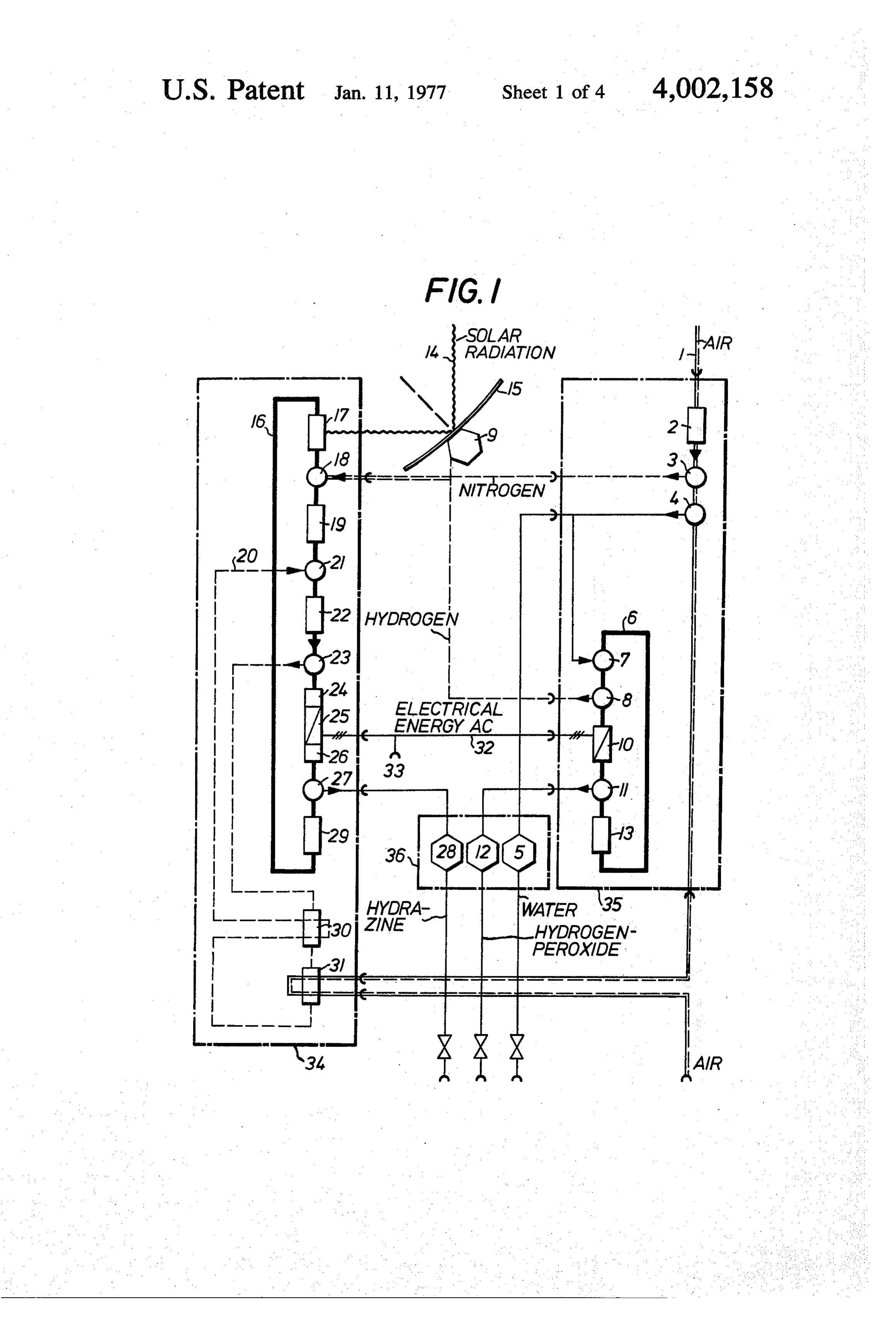
ature difference between ground and this altitude of FIG. 1 is a system diagram and flow chart for hydra about 200 K is in thermodrynamic equilibrium. That zine synthesis in accordance with the method of my equilibrium requires adiabatic insulation of the tube. copending application;
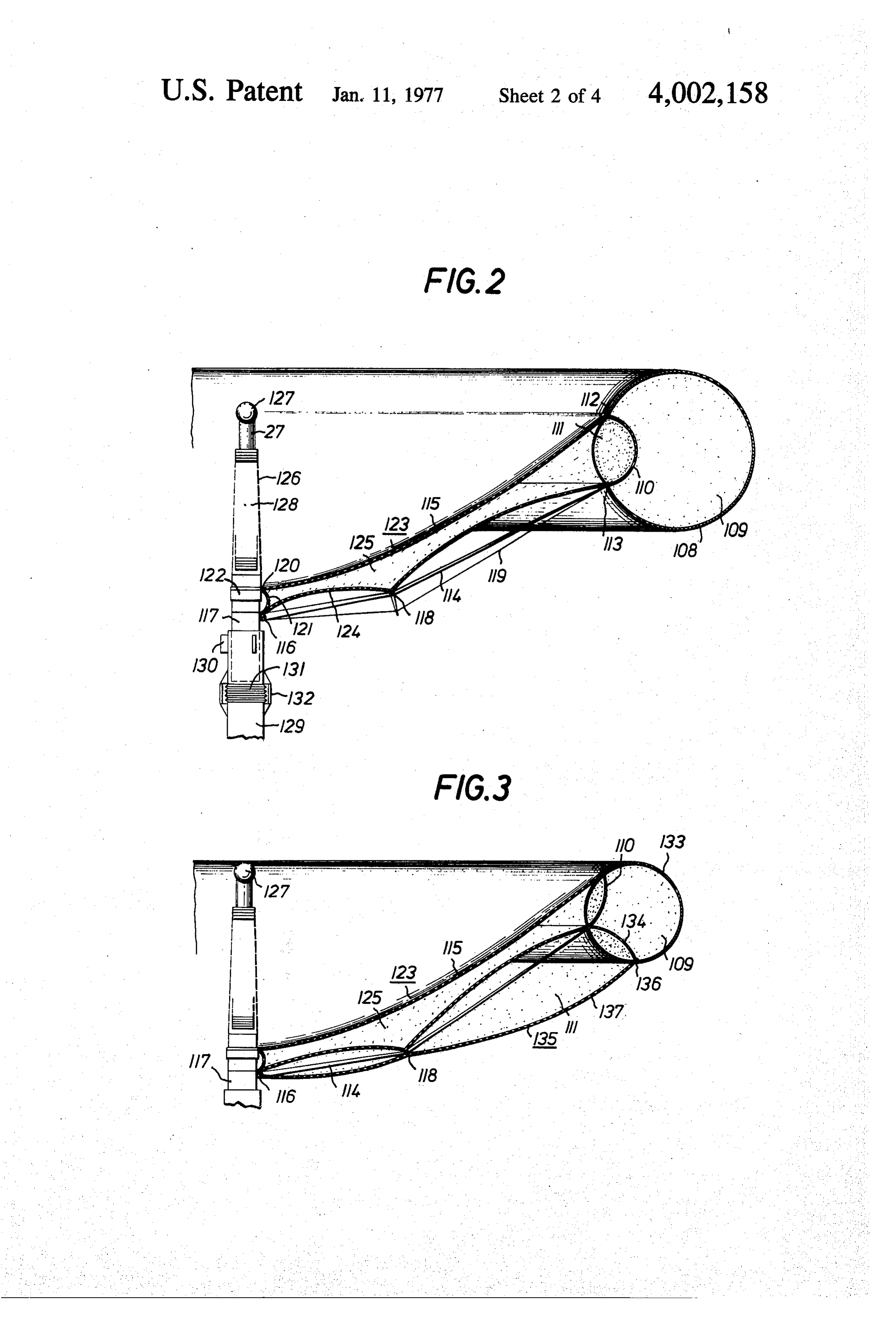
Such an isentropic temperature distribution can be FIG. 2 is a cross-section through a hollow, concave observed, indeed, up to an altitude of about 11 km, if 30 mirror stabilized by means of internal pressure differ there are no disturbances, caused by inversions and by ential.
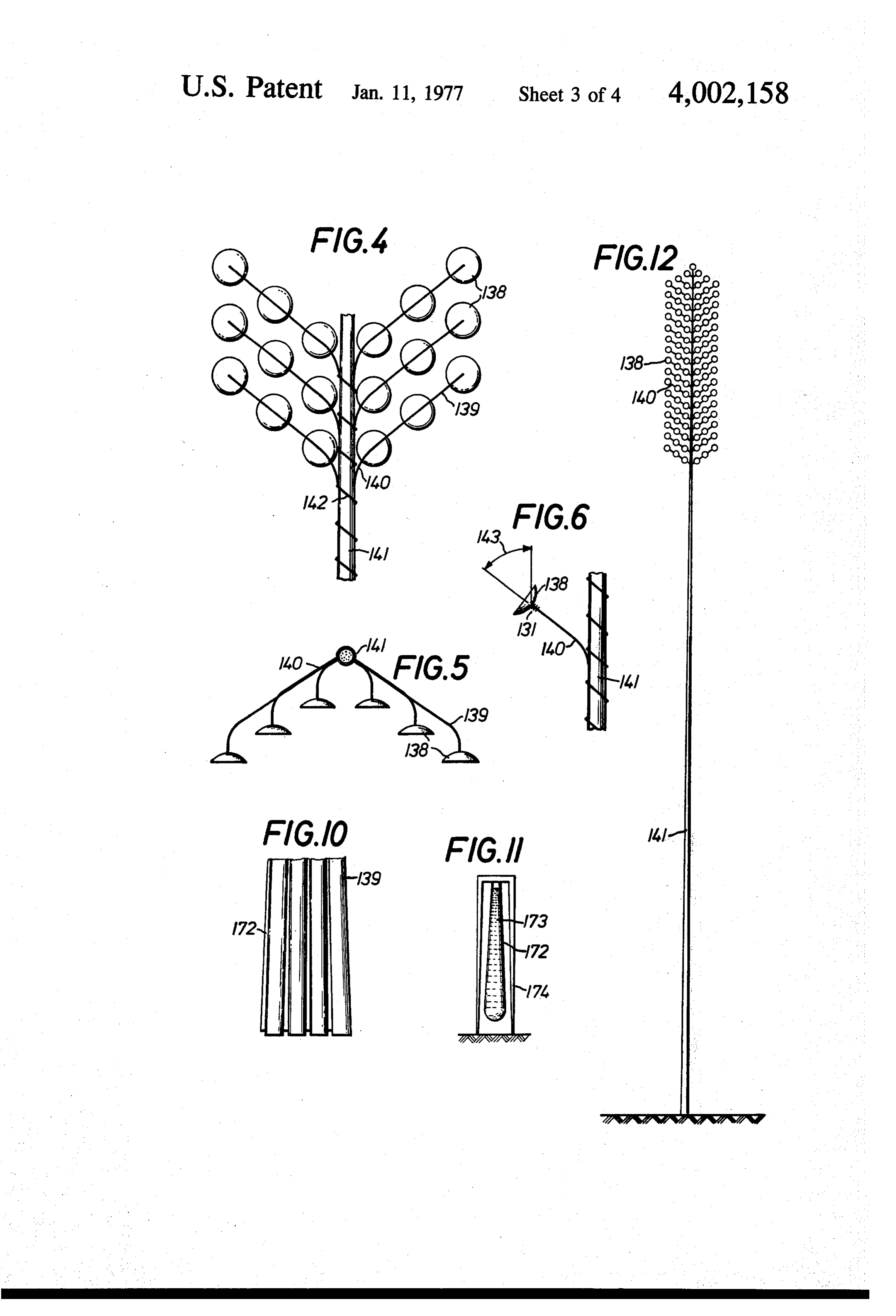
condensation of HO vapor. (The local non-equilibria FIG. 3 is a cross-section through a modified mirror; create the driving forces for the weather). FIG. 4 shows schematically an arrangement of many At elevations higher than 11 km the conditions out mirrors on a common support and reed-like tower. side of the tube are changed basically; the temperature 35 FIG. 5 is a section view through FIG. 4. is no longer determined by convection of heat that FIG. 6 is a schematic illustration of the elastic con resulted from absorption of solar radiation at the nection of mirror and reed to obtain the necessary ground, but absorption within the atmosphere becomes orientation of the mirror to the sum.
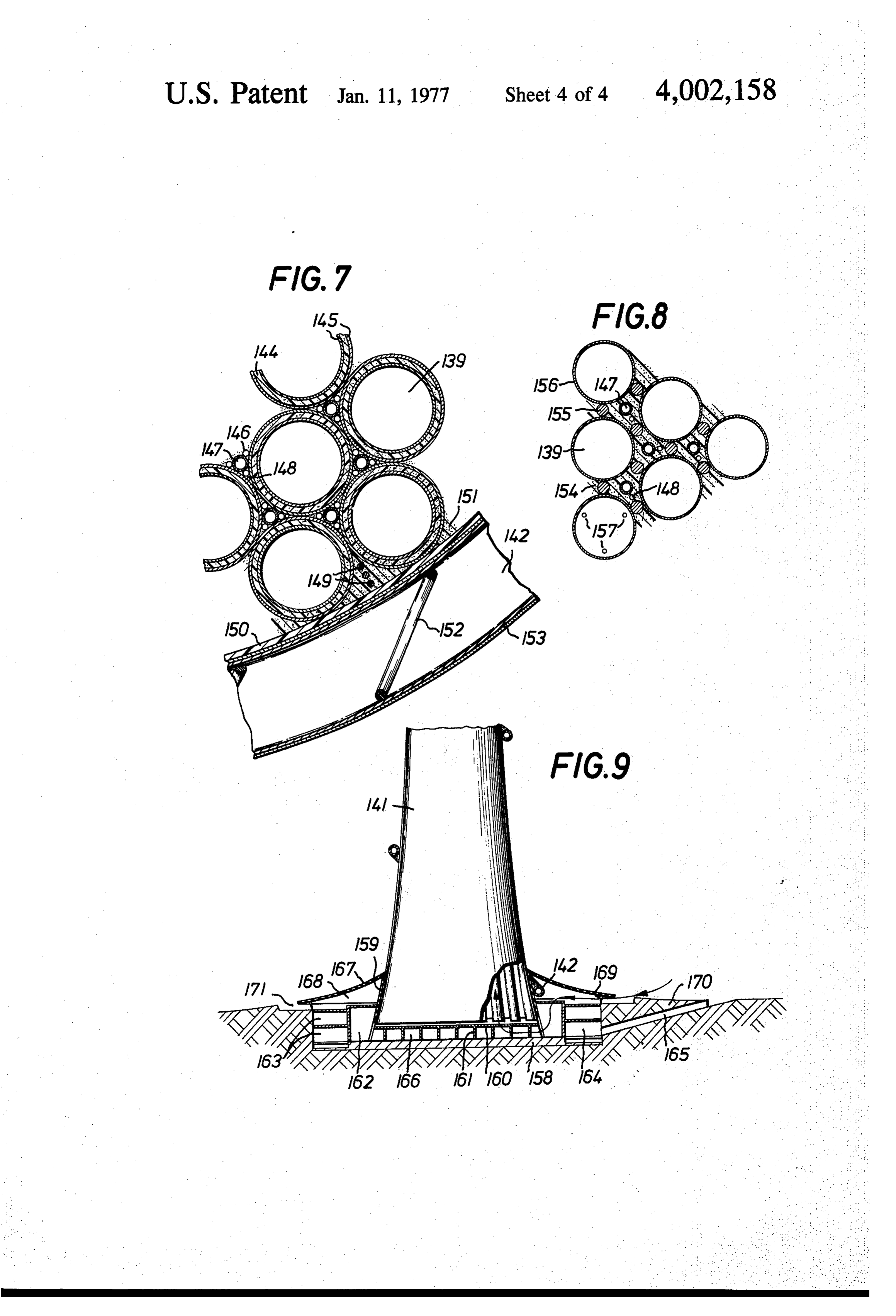
the dominating factor. The temperature distribution is FIG. 7 is a portion of a cross-section through a reed; constant, and the layers of air are isenthalpic up to an 40 FIG.FIG. 8 is a modified cross-section through a reed; altitude of 30 km. The adiabatic insulation of the tube 9 is a longitudinal section view for anchoring the reed to ground including space for auxiliary equipment will not change the isentropic temperature distribution and air intake.
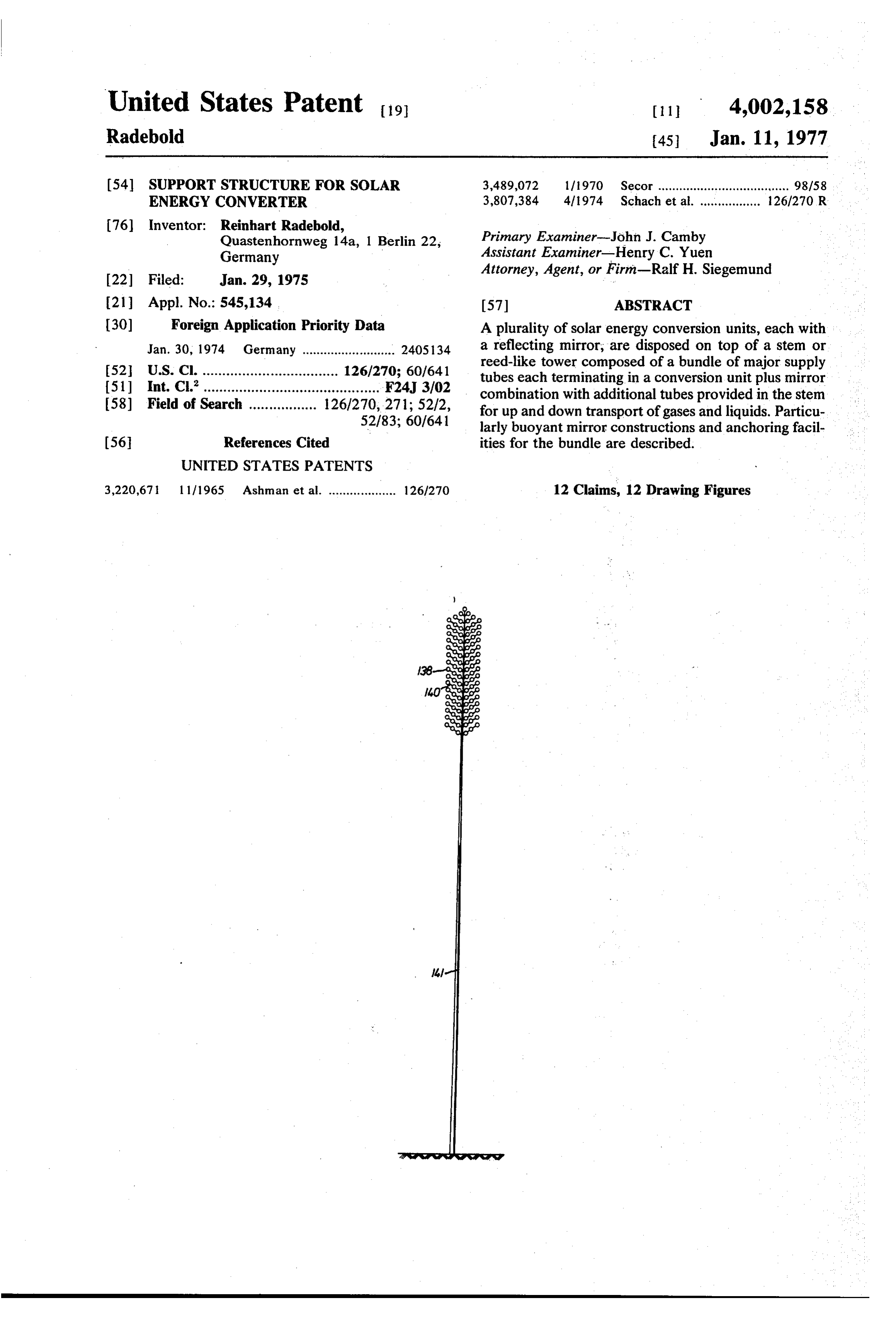
within; the air within the tube is cooler than the ambi FIG. 10 illustrates the principle of anchoring the reed ent air and the differential increases with altitude. 45 through widening of channels; To transport the cooling air to the MHD-modules, F.G. 11 shows the effect widened channels have on the total exergy demand is not, however, 200 Ws/g but the reed; and less, for it is only necessary to overcome the friction to FIG. 12 is a view drawn approximately to scale for a pass the air through the low temperature heat ex complete system as can be used in more northerly lati changer of the MHD-module. This exergy will be sup 50 tudes.
plied during condensation of HO taking place at an The basic system which is the subject of the above altitude between 3 and 4 km; the specific heat of con identified copending application is depicted in FIG. 1. densation is, if i9% of total wet air flow condensates Concerning that application, however, the system does not require a particular spatial distribution of its sub about 35 Ws/g. The specific exergy should be sufficient 55 systems for transportation; the anergy raises the temperature of and components. Presently, a particular distri bution the ascending air. By way of an example: If the temper such. Major is envisioned without modifying the system as subsystems are, a (or many) hydrazine and ature of ambient air T = 220 K at 20 km height, and if electricity generator the temperature of air within the pipe is decreased from for collecting solar energy 34 cooperating with a mirror 15 its entrance temperature T = 300 K at ground not 200 60 tem 35 is raw material generator and disposed aloft. Subsys K but to 170 K due to H2O - condensation, then the air and placed on ground.
The same is true for a storage system 36.
leaving the pipe appears to be supercooled by 220 - Air 1 is sucked into the ground system (portion 34) 130 = 90 K. Theoretically, the cooling air for the ex by means of a suction device 2, and nitrogen is sepa ergy transformer can increase its enthalpy by about 90 rated from the air at 3, while moisture is caused to Ws/g absorbing the waste heat of the process until 65 precipitate at 4 to be stored in a tank 5 on the ground reaching thermal equilibrium with the ambient air. and in the stem as will be explained shortly. Actually The air flow necessary to cool a single mirror plus precipitation 4 occurs at some distance from ground up MHD system unit under the conditions mentioned is: in the stem. The (dry) air continues up for use as cool
Page 8
ant in the subsystem 34 aloft, but the nitrogen separa ter the cushion 118 and are prestressed by cables 119 tion is also carried out aloft , for this purpose. - The water is injected at 7 into a watery solution of The mirror (or reflecting) foil 115 is connected to KOH of ground system 35 circulating along a path 6. another foil by means of a second welding seam 120 to Hydrogen is extracted from that circulation at 8 and serve as an anchoring line. Foil 121 is secured to a ring fed up in the stem and stored, in parts, in the mirror 122 right at that seam 120. This ring is pushed over the support 9. A MHD converter 10 synthetizes hydrogen central pipe 117 without being fixed and it can be dis peroxide by electrolytic process. The (OH), as pro placed and held by a drive mechanism (not shown duced is taken out of the circulation at 11 for storage here) in order to perform proper adjustment of mirror. (temporary) 12. The device 13 is an mfd - fluid prime O In order to produce the parabolic form desired of mover to sustain the circulation 8 of the watery KOH mirror foil 115, an additional mirror cushion 123 is solution. t provided which includes the mirror foil 115, the trans Solar radiation 14 is focused by a concave reflector verse foil 121 and a bottom foil 124. The bottom foil 15 on top of the stem onto a radiation absorption 124 is connected with the (toroidal) cushion 108 at the heater 17 of subsystem 34 (aloft) which heats a liquid 15 lower welding seam 113. The mirror cushion is filled consisting, basically and at first of Lithium and finely with air. at a pressure lower than that of ambient air. divided iron. Nitrogen and hydrogen respectively from The mirror cushion must, therefore, be fixed on both 3 and 8 are added to Li at 18 to obtain LiNH (as the joints 116 and 118 of the supporting arm 114 in solution in the Li) as per function box 19. order to stretch the mirror foil as desired. Pressurized N, is added to the Li-LiNH, fluid (liquid) 20 The central pipe of the mirror holds on its upper end and as a todf working gas. The pressurized Na expands one or more MHD-modules 27 by means of a support under acceleration of the liquid phase and is separated ing frame 126 (not shown in detail here); the radiation therefrom at 23. The liquid phase is focused into a jet absorption heat exchanger of MHD-module is located at 24 and subjected to MHD processing (25), whereby at the focus 127 of mirror. The exit (waste) heat ex hydrazine is produced by electrolysis of the LiNH. 25 changer of MHD-module is located at the air outflow Additionally, excess electrical energy is extracted from 128 of central pipe 117. The central pipe is, on its MHD converter 25 and fed by cable 32 down through lower end, placed into another pipe 129 to provide the the stem to ground. - connection to the supply channels 139 (not shown A jet spoiler 26 slows or stops the jet in an emer here) in stem 141. This connection or socket can be gency, but is not needed for normal operation. Hydra 30 released in order to permit replacement of the mirror zine is separated (condensed) from the liquid phase at by another new mirror, initially having being folded up. 27 to flow through the stem and into a storage 28 in the The connection is locked by means of bolts 130. The base of the stem on ground. A jet capture device 29 of connecting pipe is interrupted and made flexible by a subsystem 34 converts the residual kinetic energy of bellow 131 to permit adjustment of the mirror axis in the liquid phase into pressure to obtain return flow of 35 regard to the sun. Screws 132 stretch the bellow non the liquid (Li with residual Li NH) along path 16 to uniform by a drive mechanism (not shown here), the point of heating (17) so as to complete the circula thereby bending the connecting pipe 129 at the bel tion of that working liquid. lows.
The gaseous phase following extraction at 23 enters The mirror will be transported in folded up configu in recuperative heat exchange with itself at 30 to lose 40 ration by passing it up through the supply channel and temporarily as much thermal energy as possible for low the connecting pipe in the reed tower. After the central temperature, isothermal recompression at 31. Follow pipe 117 is fixed by the bolts 130, the (toroidal) cush ing recompression, the cold N. receives heat at 30 and ion 108 will be inflated by filling with H; the final returns to point 21. concave form of the mirror cushion 123 will be at The isothermal re-compression at 31 may involve 45 tained after the supporting arms 114 have reached their circulation of another, cooling medium, but is ulti final position by stretching the cables 119. The final mately controlled as far as temperature is concerned by adjustment of mirror form is obtained by changing the ambient air ascending through the stem and possibly axial position of ring 122.
removed by mover 1. FIG. 3 is an alternative and, actually, the preferred After having described the overall system, I proceed 50 example for a reflector and mirror; all the details com first to describe the structure of the mirror 15; later mon to both designs are omitted. The difference of this will describe the reed-like tower and stem supporting design as compared with the one shown in FIG. 2 is the system at elevated altitudes. given by the smaller (toroidal) cushion 133 and by the FIG. 2 is a radial sectional view of mirror 15 includ additional cushion 135 of stretching the arms 114 in ing particularly a support backing and buoyancy sus 55 stead of cables. 119. The advantage is to be seen in the pension for a reflecting foil 115. The construction in omission of cables as they are mechanically movable cludes a very large (toroidal) cushion 108 filled with parts; the mirror cushion reaches its final position by H., 109 to generate the total buoyancy of the mirror. inflating the stretching cushion 111 with H. The buoy The cushion 108 is reinforced and stiffened from the ancy of this cushion permits to reduce the (toroidal) inside by a compartment 110 filled with H of higher 60 cushion 108 in size.
pressure 111. The connecting welding seams 112 and The stretching cushion is formed on its top by the 113 between cushion 108 and compartment 110 offer bottom foil 124 of mirror cushion 123, on its bottom by on the one hand anchoring points for supporting arms the stretch foil 137. Stretch foil 137 and (toroidal) 114, and are on the other hand anchoring lines for the cushion 133 are connected along a welding seam 136. reflecting foil 115. The supporting arms 114 are con 65 This welding seam is stabilized from the inside by an nected to a central pipe 1 17 by joints 116. The arms additional compartment 134. The stretch cushion is each have a second joint 118 in between located nearly closed in regard to the central pipe by connecting it symmetric to both ends. The supporting arms 114 cen with the bottom foil 124 (and with the transverse foil
Page 9
121). Also, in this example, both the mirror cushion as vides thermal insulation as well as for cushioning of all well as the stretching cushion have to be fixed at the embedded tubing; the foil 150 is the blanket jacket or joint 118 of supporting arms 114. These supporting envelope of the stem. The thermal insulation 151 is arms are protected now by the H of the stretching used also to embed additional lines 149 for control and cushion to serve as a protective gas. other uses.
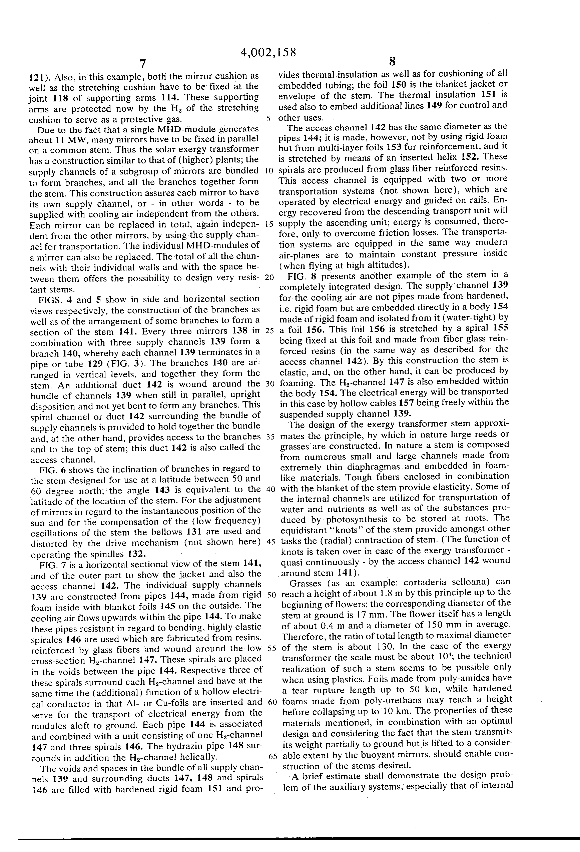
Due to the fact that a single MHD-module generates The access channel 142 has the same diameter as the about 11 MW, many mirrors have to be fixed in parallel pipes 144; it is made, however, not by using rigid foam on a common stem. Thus the solar exergy transformer but from multi-layer foils 153 for reinforcement, and it has a construction similar to that of (higher) plants; the is stretched by means of an inserted helix 152. These supply channels of a subgroup of mirrors are bundled O spirals are produced from glass fiber reinforced resins. to form branches, and all the branches together form This access channel is equipped with two or more the stem. This construction assures each mirror to have transportation systems (not shown here), which are its own supply channel, or - in other words - to be operated by electrical energy and guided on rails. En supplied with cooling air independent from the others. supplyergy recovered from the descending transport unit will Each mirror can be replaced in total, again indepen 5 the ascending unit; energy is consumed, there dent from the other mirrors, by using the supply chan fore, only to overcome friction losses. The transporta nel for transportation. The individual MHD-modules of tion systems are equipped in the same way modern a mirror can also be replaced. The total of all the chan air-planes are to maintain constant pressure inside nels with their individual walls and with the space be (when flying at high altitudes).
tween them offers the possibility to design very resis 20 FIG. 8 presents another example of the stem in a tant StemS. completely integrated design. The supply channel 139 FIGS. 4 and 5 show in side and horizontal section for the cooling air are not pipes made from hardened, views respectively, the construction of the branches as i.e. rigid foam but are embedded directly in a body 154 well as of the arrangement of some branches to form a made of rigid foam and isolated from it (water-tight) by section of the stem 141. Every three mirrors 138 in 25 a foil 156. This foil 156 is stretched by a spiral 155 combination with three supply channels 139 form a being fixed at this foil and made from fiber glass rein branch 140, whereby each channel 139 terminates in a forced resins (in the same way as described for the pipe or tube 129 (FIG. 3). The branches 140 are ar access channel 142). By this construction the stem is ranged in vertical levels, and together they form the elastic, and, on the other hand, it can be produced by stem. An additional duct 142 is wound around the 30 foaming. The H-channel 147 is also embedded within bundle of channels 139 when still in parallel, upright the body 154. The electrical energy will be transported disposition and not yet bent to form any branches. This in this case by hollow cables 157 being freely within the spiral channel or duct 142 surrounding the bundle of suspended supply channel 139.
supply channels is provided to hold together the bundle The design of the exergy transformer stem approxi and, at the other hand, provides access to the branches 35 mates the principle, by which in nature large reeds or and to the top of stem; this duct 142 is also called the grasses are constructed. In nature a stem is composed access channel. from numerous small and large channels made from FIG. 6 shows the inclination of branches in regard to extremely thin diaphragmas, and embedded in foam the stem designed for use at a latitude between 50 and like materials. Tough fibers enclosed in combination 60 degree north; the angle 143 is equivalent to the 40 with the blanket of the stem provide elasticity. Some of latitude of the location of the stem. For the adjustment the internal channels are utilized for transportation of of mirrors in regard to the instantaneous position of the water and nutrients as well as of the substances pro duced by photosynthesis to be stored at roots. The sun and for the compensation of the (low frequency) equidistant oscillations of the stem the bellows 131 are used and 'knots' of the stem provide amongst other distorted by the drive mechanism (not shown here) 45 tasks the (radial) contraction of stem. (The function of operating the spindles 132. knots is taken over in case of the exergy transformer - FIG. 7 is a horizontal sectional view of the stem 141, quasi continuously - by the access channel 142 wound and of the outer part to show the jacket and also the around stem 141).
access channel 142. The individual supply channels reach Grasses (as an example: cortaderia selloana) can 139 are constructed from pipes 144, made from rigid 50 a height of about 1.8 m by this principle up to the foam inside with blanket foils 145 on the outside. The beginning of flowers; the corresponding diameter of the cooling air flows upwards within the pipe 144. To make stem at ground is 17 mm. The flower itself has a length these pipes resistant in regard to bending, highly elastic of about 0.4 m and a diameter of 150 mm in average. spirales 146 are used which are fabricated from resins, Therefore, the ratio of total length to maximal diameter reinforced by glass fibers and wound around the low 55 of the stem is about 130. In the case of the exergy cross-section H-channel 147. These spirals are placed transformer the scale must be about 10; the technical in the voids between the pipe 144. Respective three of realization of such a stem seems to be possible only these spirals surround each H-channel and have at the when using plastics. Foils made from poly-amides have same time the (additional) function of a hollow electri a tear rupture length up to 50 km, while hardened cal conductor in that Al- or Cu-foils are inserted and foams made from poly-urethans may reach a height serve for the transport of electrical energy from the before collapsing up to 10 km. The properties of these modules aloft to ground. Each pipe 144 is associated materials mentioned, in combination with an optimal and combined with a unit consisting of one H-channel design and considering the fact that the stem transmits 147 and three spirals 146. The hydrazin pipe 148 sur its weight partially to ground but is lifted to a consider rounds in addition the H-channel helically. 65 able extent by the buoyant mirrors, should enable con The voids and spaces in the bundle of all supply chan struction of the stems desired. nels 139 and surrounding ducts 147, 148 and spirals A brief estimate shall demonstrate the design prob 146 are filled with hardened rigid foam 151 and pro lem of the auxiliary systems, especially that of internal
Page 10
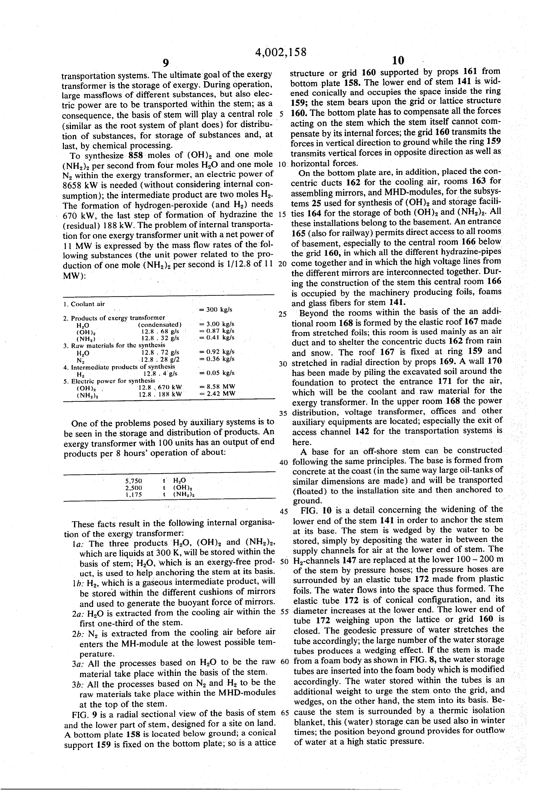
transportation systems. The ultimate goal of the exergy structure or grid 160 supported by props 161 from transformer is the storage of exergy. During operation, bottom plate 158. The lower end of stem 141 is wid large massflows of different substances, but also elec ened conically and occupies the space inside the ring tric power are to be transported within the stem; as a 159; the stem bears upon the grid or lattice structure consequence, the basis of stem will play a central role 160. The bottom plate has to compensate all the forces (similar as the root system of plant does) for distribu acting on the stem which the stem itself cannot com tion of substances, for storage of substances and, at pensate by its internal forces; the grid 160 transmits the last, by chemical processing. forces in vertical direction to ground while the ring 159 To synthesize 858 moles of (OH) and one mole transmits vertical forces in opposite direction as well as (NH), per second from four moles HO and one mole 10. horizontal forces.
On the bottom plate are, in addition, placed the con
N, within the exergy transformer, an electric power of 8658 kW is needed (without considering internal con centric ducts 162 for the cooling air, rooms 163 for sumption); the intermediate product are two moles H. assembling mirrors, and MHD-modules, for the subsys The formation of hydrogen-peroxide (and H) needs tems 25 used for synthesis of (OH), and storage facili 670 kW, the last step of formation of hydrazine the 15 ties 164 for the storage of both (OH), and (NH). All (residual) 188 kW. The problem of internal transporta these installations belong to the basement. An entrance tion for one exergy transformer unit with a net power of 165 (also for railway) permits direct access to all rooms 11 MW is expressed by the mass flow rates of the fol of basement, especially to the central room 166 below lowing substances (the unit power related to the pro the grid 160, in which all the different hydrazine-pipes duction of one mole (NH) per second is 1/12.8 of 11 20 come together and in which the high voltage lines from MW): the different mirrors are interconnected together. Dur ing the construction of the stem this central room 166 is occupied by the machinery producing foils, foams l. Coolant air
and glass fibers for stem 141.
2. Products of cxergy transformer 25 Beyond the rooms within the basis of the an addi HO (condensatcd) = 3.00 kg/s tional room 168 is formed by the elastic roof 167 made
from stretched foils; this room is used mainly as an air 3. Raw materials for the synthesis duct and to shelter the concentric ducts 162 from rain
and snow. The roof 167 is fixed at ring 159 and 4. Intcrmcdiate products of synthesis 30 stretched in radial direction by props 169. A wall 170 H 12.8 . 4 g/s = 0.05 kg/s has been made by piling the excavated soil around the 5. Elcctric power for synthcs.is foundation to protect the entrance 171 for the air,
(NH), 2.8, 88 kW = 2.42 MW which will be the coolant and raw material for the exergy transformer. In the upper room 168 the power 35 distribution, voltage transformer, offices and other
One of the problems posed by auxiliary systems is to auxiliary equipments are located; especially the exit of be seen in the storage and distribution of products. An access channel 142 for the transportation systems is exergy transformer with 100 units has an output of end here.
A base for an off-shore stem can be constructed products per 8 hours' operation of about:
40 following the same principles. The base is formed from concrete at the coast (in the same way large oil-tanks of
similar dimensions are made) and will be transported 75 t (NH) (floated) to the installation site and then anchored to ground.
45 FIG. 10 is a detail concerning the widening of the
These facts result in the following internal organisa lower end of the stem 141 in order to anchor the stem tion of the exergy transformer: at its base. The stem is wedged by the water to be la: The three products H2O, (OH), and (NH2)2, stored, simply by depositing the water in between the which are liquids at 300 K, will be stored within the supply channels for air at the lower end of stem. The basis of stem; HO, which is an exergy-free prod 50 H-channels 147 are replaced at the lower 100-200 m uct, is used to help anchoring the stem at its basis. of the stem by pressure hoses; the pressure hoses, are 1b: H, which is a gaseous intermediate product, will surrounded by an elastic tube 172 made from plastic be stored within the different cushions of mirrors foils. The water flows into the space thus formed. The and used to generate the buoyant force of mirrors. elastic tube 172 is of conical configuration, and its 2a: HO is extracted from the cooling air within the 55 diameter increases at the lower end. The lower end of first one-third of the stem. tube 172 weighing upon the lattice or grid 160 is 2b: N is extracted from the cooling air before air closed. The geodesic pressure of water stretches the enters the MH-module at the lowest possible tem tube accordingly; the large number of the water storage tubes produces a wedging effect. If the stem is made perature.
3a. All the processes based on HO to be the raw 60 from a foam body as shown in FIG. 8, the water storage material take place within the basis of the stem. tubes are inserted into the foam body which is modified 3b. All the processes based on N, and H2 to be the accordingly. The water stored within the tubes is an raw materials take place within the MHD-modules additional weight to urge the stem onto the grid, and at the top of the stem. wedges, on the other hand, the stem into its basis. Be FIG. 9 is a radial sectional view of the basis of stem 65 cause the stem is surrounded by a thermic isolation and the lower part of stem, designed for a site on land. blanket, this (water) storage can be used also in winter A bottom plate 158 is located below ground; a conical times; the position beyond ground provides for outflow support 159 is fixed on the bottom plate; so is a attice of water at a high static pressure.
Page 11
The gaseous HO, condensed within the stem at an exergy transformer is characterized by the numbers mentioned above.
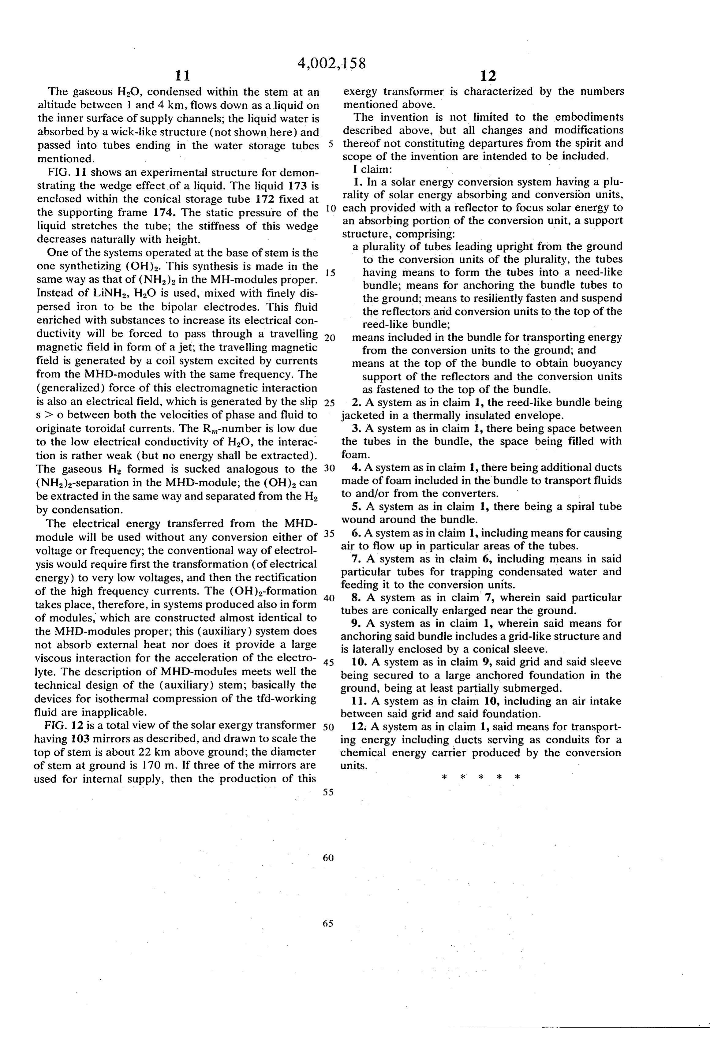
altitude between 1 and 4 km, flows down as a liquid on the inner surface of supply channels; the liquid water is The invention is not limited to the embodiments absorbed by a wick-like structure (not shown here) and described above, but all changes and modifications passed into tubes ending in the water storage tubes thereof not constituting departures from the spirit and mentioned. scope of the invention are intended to be included. FIG. 1 i shows an experimental structure for demon I claim:
strating the wedge effect of a liquid. The liquid 173 is 1. In a solar energy conversion system having a plu rality of solar energy absorbing and conversion units, enclosed within the conical storage tube 172 fixed at O each provided the supporting frame 174. The static pressure of the an absorbing portion with a reflector to focus solar energy to liquid stretches the tube; the stiffness of this wedge structure, comprising:of the conversion unit, a support decreases naturally with height. a plurality of tubes leading upright from the ground One of the systems operated at the base of stem is the to the conversion units of the plurality, the tubes one synthetizing (OH)2. This synthesis is made in the S having means to form the tubes into a need-like same way as that of (NH) in the MH-modules proper. bundle; means for anchoring the bundle tubes to Instead of LiNH2, H2O is used, mixed with finely dis the ground; means to resiliently fasten and suspend persed iron to be the bipolar electrodes. This fluid the reflectors and conversion units to the top of the enriched with substances to increase its electrical con reed-like bundle; r ductivity will be forced to pass through a travelling 20 means included in the bundle for transporting energy magnetic field in form of a jet; the travelling magnetic from the conversion units to the ground; and field is generated by a coil system excited by currents means at the top of the bundle to obtain buoyancy from the MHD-modules with the same frequency. The support of the reflectors and the conversion units (generalized) force of this electromagnetic interaction as fastened to the top of the bundle. is also an electrical field, which is generated by the slip 25 2. A system as in claim 1, the reed-like bundle being s > o between both the velocities of phase and fluid to jacketed in a thermally insulated envelope. originate toroidal currents. The R-number is low due 3. A system as in claim 1, there being space between to the low electrical conductivity of HO, the interac the tubes in the bundle, the space being filled with tion is rather weak (but no energy shall be extracted). foam.
The gaseous H formed is sucked analogous to the 30 4. A system as in claim , there being additional ducts (NH)-separation in the MHD-module; the (OH)2 can made of foam included in the bundle to transport fluids be extracted in the same way and separated from the H. to and/or from the converters.
by condensation. 5. A system as in claim 1, there being a spiral tube The electrical energy transferred from the MHD 35 wound 6. A around the bundle.
system as in claim 1, including means for causing module will be used without any conversion either of voltage or frequency; the conventional way of electrol air to flow up in particular areas of the tubes. 7. A system as in claim 6, including means in said ysis would require first the transformation (of electrical particular energy) to very low voltages, and then the rectification feeding it totubes for trapping condensated water and of the high frequency currents. The (OH)2-formation 40 8. A system as in claim 7,units.
the conversion wherein said particular takes place, therefore, in systems produced also in form tubes are conically enlarged near the ground. of modules, which are constructed almost identical to the MHD-modules proper; this (auxiliary) system does anchoring said bundle includes a grid-likesaid 9. A system as in claim 1, wherein means for structure and not absorb external heat nor does it provide a large is laterally enclosed by a conical sleeve. viscous interaction for the acceleration of the electro 45 10. A system as in claim 9, said grid and said sleeve lyte. The description of MHD-modules meets well the being secured to a large anchored foundation in the technical design of the (auxiliary) stem; basically the ground, being at least partially submerged. devices for isothermal compression of the tifa-working 11. A system as in claim 10, including an air intake fluid are inapplicable. between said grid and said foundation. FIG. 12 is a total view of the solar exergy transformer 50 12. A system as in claim 1, said means for transport having 103 mirrors as described, and drawn to scale the ing energy including ducts serving as conduits for a top of stem is about 22 km above ground; the diameter chemical energy carrier produced by the conversion of stem at ground is 170 m. If three of the mirrors are units.
used for internal supply, then the production of this ; : k k sk
Provenance
- Collection
- Cited prior art
- Original PDF
- patentimages.storage.googleapis.com →
- Filed
- 1975-01-29
- Pages
- 11
- Method
- pdftotext (the PDF's own text layer) + pdftoppm 300dpi page scans
- Source
- Google Patents bibliographic record
- Granted
- 1977-01-11
- Inventors
- Reinhart Radebold
- Transcribed from
- patentimages.storage.googleapis.com →