patent · US5297515A
Fuel supply systems for engines and combustion processes therefor
29 March 1994
Page 1 — bibliographic record
United States Patent 19 (11) Patent Number: 5,297,515 Gale et al. (45) Date of Patent: Mar. 29, 1994 (54) FUEL SUPPLY SYSTEMS FOR ENGINES 4,108,114 8/1978 Kosaka et al. . AND COMBUSTION PROCESSES 4,131,086 12/1978 Noguchi et al. . THEREFOR 4,131,095 12/1978 Ouchi.
4,175,523 11/1979 Noguchi................................. 123/3 75 Inventors: Nigel F. Gale; David W. Naegeli; 4,181,100 l/1980 Yamane et al. . Thomas W. Ryan, III; Steven R. King, 4,244,328 1/1981 Lindstrom .............................. 123/3 all of San Antonio, Tex. 4,389,981 6/1983 Meyer ......................... 123/DIG. 12
73) Assignee: Southwest Research Institute, San 4,715,326 12/1987 Thring .................................... 123/3 Antonio, Tex. 5,178,119 1/1993 Gale ............................ 123/DG, 12 21) Appl. No.: 58,317 Primary Examiner-E. Rollins Cross 22 Filed: May 3, 1993 Assistant Examiner-Erick Solis Attorney, Agent, or Firm-Baker & Botts
Related U.S. Application Data 57 ABSTRACT (63) Continuation of Ser. No. 846,025, Mar. 5, 1992. An engine is provided which, in at least one cylinder or (51) Int. Cli.............................................. FO2B 43/08 combustion area, is provided with a hydrocarbon rich (52) U.S.C. ................................... 123/3; 123/59 EC; fuel which produces upon combustion an exhaust gas 123/570; 60/614 containing unburned hydrocarbons, water vapor and 58) Field of Search ................... 123/3, DIG. 12, 570, carbon monoxide. The exhaust gas is treated in a cata 123/568, 59 EC; 60/614, 619, 620, 622 lytic converter and the reaction process that occurs 56 References Cited therein produces hydrogen and carbon dioxide which is mixed with air to form a hydrocarbon lean, hydrogen
3,924,576 12/1975 Siewert ................................. 60/620 other cylinders or combustion areas of the engine to 4,041,910 8/1977 Houseman...................... 123/59 EC produce power.
4,079,703 3/1978 Yamane et al. . 7 Claims, 1 Drawing Sheet
Page 2
Drawing sheet — no readable text.
Page 3
duced amounts of unburned hydrocarbons and reduced
FUEL SUPPLY SYSTEMS FOR ENGINES AND amounts of oxides of nitrogen. COMBUSTION PROCESSES THEREFOR In another aspect, this invention provides an im proved engine fuel supply system that includes: a first
CROSS REFERENCE TO RELATED fuel supply for supplying a hydrocarbon enriched fuel APPLICATIONS to a first combustion chamber in the engine for produc This application is a continuation application of U.S. ing exhaust gas containing carbon monoxide, oxides of application Ser. No. 07/846,025, filed Mar. 5, 1992 and nitrogen, unburned hydrocarbons, water vapor and hydrogen; a second fuel supply for supplying hydrocar entitled "Fuel Supply Systems for Engines and Com 10 bon lean fuel to a second combustion chamber in the bustion Processes Therefore" by Nigel F. Gale, David engine; conduit means connecting the combustion W. Naegeli, Thomas W. Ryan III and Steven R. King. chambers; and a water-gas shift catalyst located in the TECHNICAL FIELD OF THE INVENTION conduit for receiving the exhaust gas from the first This invention relates generally to engines. More 15 ide combustion chamber, for converting the carbon monox and water in the exhaust gas to a mixture containing particularly, but not by way of limitation, this invention hydrogen relates to improved fuel supply systems and combustion mixture toand carbon dioxide and for delivering the a second combustion chamber wherein the processes for both reciprocating and gas turbine engines mixture and hydrocarbon lean fuel are mixed and wherein hydrogen gas and hydrocarbon fuels are uti burned to power the engine, producing an exhaust hav lized in 20 ing reduced amounts of oxides of nitrogen and reduced BACKGROUND OF THE INVENTION amounts of unburned hydrocarbons.
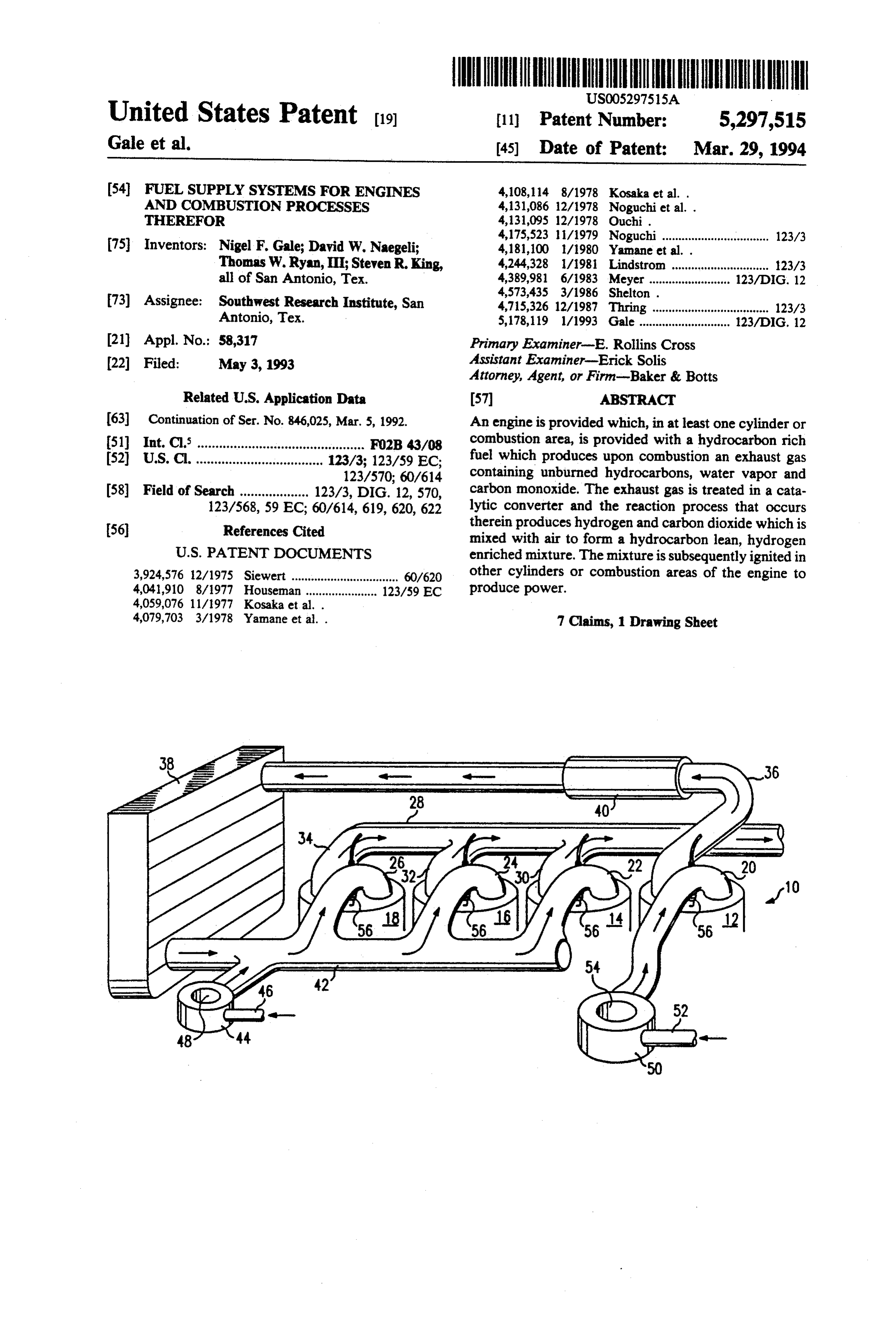
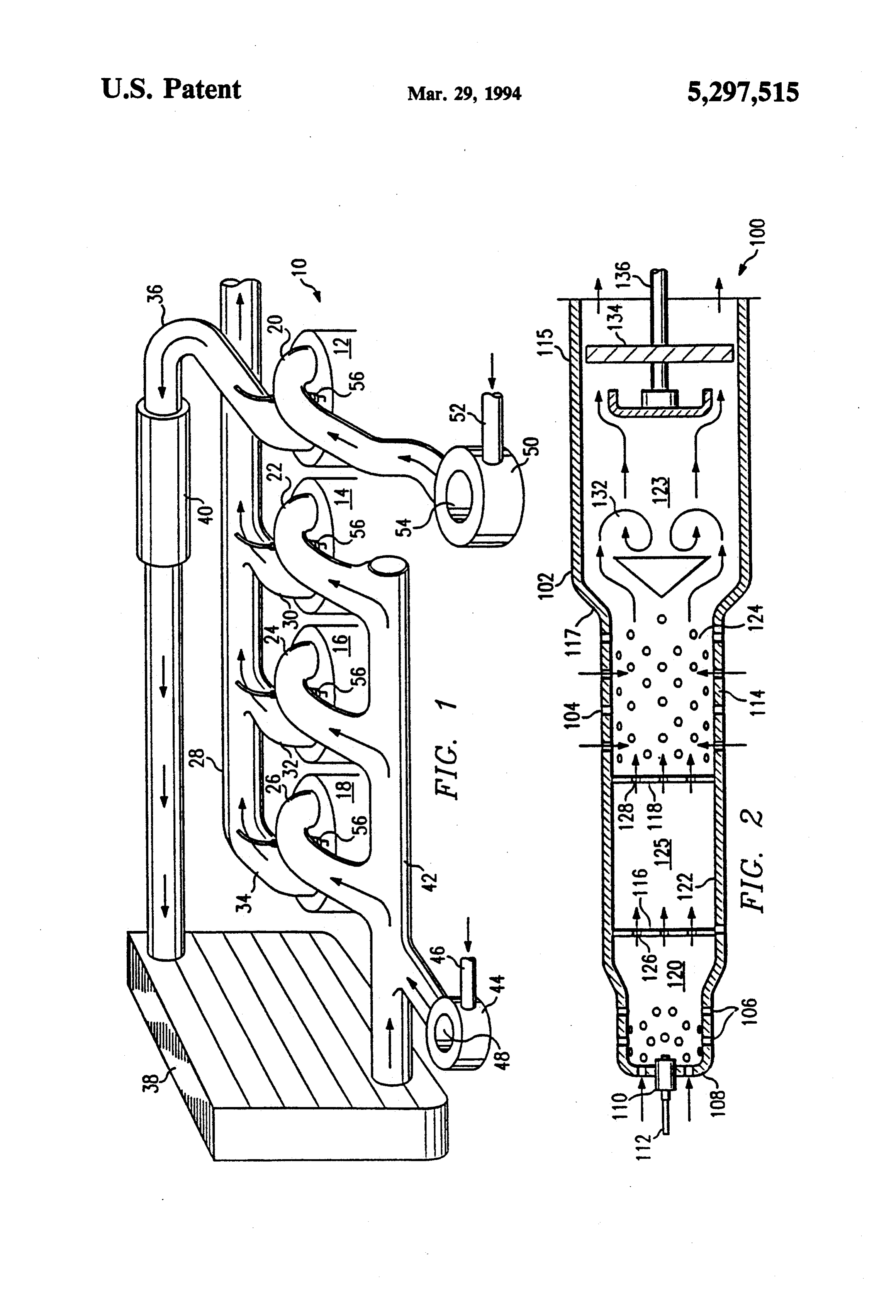
Attempts have been made in the past to produce BRIEF DESCRIPTION OF THE DRAWING engines which utilize a portion of the cylinders for The foregoing and additional objects and advantages generating a hydrogen rich exhaust gas which is then 25 of the invention will become more apparent as the fol combined with hydrocarbon fuel in a carburetor and lowing detailed description is read in conjunction with delivered to the remaining cylinders of the engine for the accompanying drawing, wherein like reference combustion. One such system is illustrated in U.S. Pat. characters denote like parts in all views and wherein: No. 4,041,910, issued to John Houseman on Aug. 16, FIG. 1 illustrates a fuel supply system constructed in 1977. A similar system is illustrated in U.S. Pat. No. 30 accordance with the invention that is utilized in connec 4,108,114, issued to Katuaki Kosaka, et al. on Aug. 22, tion with a reciprocating engine; and 1978. In each of the above patents, the exhaust gas is FIG. 2 is a cross-sectional view illustrating a fuel virtually untreated and is returned to the cylinder for supply system that is also constructed in accordance the complete combustion of the unburned hydrocar with the invention and showing the system applied to a bons and any free hydrogen that may be contained 35 gas turbine engine.
therein. DETALED DESCRIPTION OF THE U.S. Pat. No. 4,059,076 issued to Katuaki Kosaka, et PREFERRED EMBODIMENT al. on Nov. 22, 1977, illustrates use of a separate engine for generating a hydrogen rich exhaust gas which is Referring to the drawing and to FIG. 1 in particular, subsequently burned in the main power engine. In the schematically illustrated therein, is an engine generally designated by the reference character 10 that includes a system described in the '076 patent, the exhaust gas is plurality mixed with hydrocarbon fuel and then passed through a are each ofprovidedcylinders 12, 14, 16 and 18. The cylinders with an intake port connected to catalytic converter prior to being delivered to the main intake pipes 20, 22, 24 and 26, respectively. The engine power engine.
An object of this invention is to provide an improved 45 nected 10 also includes an exhaust manifold 28 that is con to the cylinders 14, 16 and 18 to exhaust ports fuel system and combustion process for use with both and connecting exhaust pipes 30, 32 and 34. reciprocating and gas turbine engines wherein hydro gen rich exhaust gas is generated in the engine, passed exhaust pipe or 12
The cylinder also includes an exhaust port. An conduit 36 extends from the exhaust through a water-gas shift catalyst to further increase its port of the cylinder 12 to an intercooler or heat ex hydrogen content, then mixed with a lean hydrocarbon changer 38. Connected into the exhaust pipe 36 is a fuel for burning in the remainder of the engine. catalytic converter 40. The converter 40 preferably SUMMARY OF THE INVENTION includes a nickel or platinum catalyst. The catalyst is effective
In one aspect, this invention provides an improved 55 gas. in a water-gas shift reaction with the exhaust fuel combustion process that reduces emissions of un An intake manifold 42 extends from the intercooler burned hydrocarbons, carbon monoxide and oxides of 38 to the intake pipes 22, 24 and 26. Carburetor 44 is nitrogen. The process includes the steps of burning a hydrocarbon rich fuel in a first combustion chamber in connected to the intake manifold 42 and is provided for the purpose of mixing fuel and air and delivering a the engine; producing an exhaust gas containing carbon hydrocarbon lean fuel into the intake manifold 42. Fuel monoxide, oxides of nitrogen, unburned hydrocarbons, supply pipe 46 is connected with the carburetor 44. Air water vapor and hydrogen; catalytically shifting the for mixing with the fuel in the carburetor 44 is drawn in carbon monoxide and water in the exhaust gas to a through a filtered opening 48 in the carburetor 44. mixture containing hydrogen and carbon dioxide; mix A second carburetor 50 is connected through the ing the mixture with hydrocarbon lean fuel to form a 65 intake pipe 20 to the cylinder 12. Like the carburetor 44, hydrogen enriched inlet gas; and burning the inlet gas in the carburetor 50 also includes a fuel supply pipe 52 and a second combustion chamber in the engine to power an air intake port 54 which is generally filtered, for the engine and produce engine exhaust containing re allowing air in the carburetor to mix with the fuel. The
Page 4
carburetor 50 provides a hydrocarbon rich fuel for through the end 108 and is connected by conduit 112 delivery to the engine 10. with a source of fuel.
Each of the cylinders is also provided with a spark A reduced diameter portion 114 of the housing 102 is plug 56 or similar fuel igniting device for initiating com disposed coaxially with a larger diameter portion 115 of bustion of fuel in each of the cylinders. Although not the housing 102 and is connected with the housing 102 shown, it will be understood that appropriate fuel con by the transition portion 117 as illustrated in FIG.2. trol or throttling devices and appropriate ignition con Spaced partitions 116 and 118 are located within the trols will be provided for the engine 10. portion 114 and divide the housing 102 into four cham Operation of the Embodiment of FIG. 1 bers 120, 122, 123 and 124. The portion 114 forms a 10 conduit from the chamber 120 to the chamber 124. A
In the operation of the engine 10, a hydrocarbon rich catalytic converter 125 is located in the chamber 122. fuel/air mixture is formed in the carburetor 50 and The catalytic converter 125 contains one or more of the delivered to the intake pipe 20 of the cylinder 12. In the catalysts listed hereinbefore.
cylinder 12, the fuel is ignited by the spark plug 56. The chamber 120 receives a fuel charge from the Since the fuel is hydrocarbon rich and well above the 15 nozzle 110 and receives air through the ports 106 form stoichiometric range, few oxides of nitrogen are pro ing a hydrocarbon rich fuel. Although not illustrated, duced during combustion. However, substantial an igniter will be located in chamber 120 which initiates amounts of unburned hydrocarbon, carbon monoxide, combustion of the completely premixed fuel/air mix water vapor, carbon dioxide and hydrogen are pro ture.
duced. Exhaust gas from the cylinder 12 is expelled 20 In order to maintain the oxides of nitrogen low, the through the exhaust conduit 36, passing through the fuel in the chamber 120 is supplied hydrocarbon rich, catalytic converter 40. that is, the fuel/air ratio is above stoichiometric. Since In the catalytic converter 40, the carbon monoxide the fuel is rich, it provides a substantial amount of un and water in the exhaust gas are converted to additional burned hydrocarbon, carbon monoxide, and water hydrogen and carbon dioxide. This process is well 25 vapor in the exhaust gas created by the combustion in known as the water-gas shift reaction. Chemically, the the chamber 120.
water-gas shift reaction may be represented as Exhaust ports 126 are provided in the partition 116 and exhaust ports 128 are provided in the partition 118.
Accordingly, combustion of the fuel in the chamber 120 30 generates exhaust gases which pass through the ports
In the reaction, the carbon monoxide in the exhaust is 126, through the catalytic converter 125 located in the exchanged for hydrogen. The water-gas shift reaction is chamber 122, and exit through the ports 128 into the exothermic by 9 kcal/mol and the equilibrium constant chamber 124. The chamber 124 is a mixing chamber is about 30 at 1,000K (1341. F.), so the indicated result wherein the gases passing through the converter are of the reaction is that formation of hydrogen and carbon 35 mixed with air.
dioxide are favored. In the presence of a catalyst, the As previously described in connection with FIG. 1, reaction is fast so equilibrium is established rapidly. exhaust gases passing through the catalytic converter Suitable catalytic materials include nickel, platinum, 125 are subjected to the water-gas shift reaction with cobalt, ruthenium and palladium. In some instances, the resulting production of hydrogen and carbon diox combinations may be used advantageously. ide.
After the exhaust passes through the catalytic con The gases exiting from the catalytic converter 125 are verter 40 it enters the intercooler 38 where the tempera mixed with air which is drawn in through the ports 104 ture of the hydrogen enriched exhaust gas is lowered enough to prevent premature combustion when the gas in the portion 114 of the housing 102. The arrangement is such that the fuel/air mixture in the chamber 124 will is mixed with air. The exhaust gas enters the inlet mani 45 hydrocarbon lean and hydrogen enriched. That is, fold 42 and mixes with a fuel-lean hydrocarbon-air mix be the fuel/air ratio is below stoichiometric. ture which is provided by the carburetor 44, forming an The fuel and air are mixed in the chamber 124 passing inlet fuel mixture that is hydrogen enriched and hydro outwardly therefrom into the enlarged portion 115 of carbon lean. The inlet fuel mixture enters the cylinders the housing 102 wherein the mixture will be ignited in 14, 16 and 18 through the corresponding intake pipes 50 ignition chamber 123 in the area indicated by the refer 22, 24 and 26 where the inlet fuel mixture is burned to ence character 132. Gases produced by the ignition at provide power to the engine 10.
Exhaust gases produced upon combustion of the inlet attacheddirected 132 are through a turbine wheel 134 which is to and causes rotation of the shaft 136.
mixture in the cylinders 14, 16 and 18 contain little, if any, unburned hydrocarbons. It contains also a substan 55 theItcombustion should be pointed out that the gases resulting from at 132 will contain no unburned hydro tially reduced amount of oxides of nitrogen as com carbons and contain very low oxides of nitrogen. pared to the usual exhaust gases.
The Embodiment of FIG. 2 Operation of the Embodiment of FIG. 2 Referring to the drawing and to FIG. 2, shown 100, a premixedWhen it is desired to operate the gas turbine engine therein and generally designated by the reference char the chamber 120mixture of fuel and air is admitted into acter 100 is a portion of a gas turbine engine. The por pass through the ports 126 and occurs. where ignition Exhaust gases through the catalytic tion of the gas turbine engine 100 shown may be gener converter 125 in the chamber 122 wherein the water ally referred to as the combustor section of the engine. gas shift reaction occurs producing an exhaust gas con The gas turbine engine 100 includes a generally tubu 65 lar outer housing 102 having perforations 104 extending taining is then hydrogen and carbon dioxide. This exhaust gas mixed with air in the chamber 124 and ignited at therethrough. Perforations 106 are provided in a closed 132 to produce end 108 of the housing 102. A gas nozzle 110 extends wheel 134 and theexhaust gas which drives the turbine attached shaft 136. The exhaust gas is
Page 5
essentially, if not totally, free of unburned hydrocar chamber, for using a water-gas shift reaction to bons and will contain very low amounts of oxides of produce a mixture containing hydrogen and carbon nitrogen. dioxide, and for delivering said mixture to said From the foregoing, it will be appreciated that an second combustion chamber wherein said mixture engine constructed in accordance with the invention, and air are mixed and burned to power the engine whether a reciprocating engine or gas turbine engine, producing an exhaust having reduced amounts of includes a fuel supply system and a fuel combustion oxides of nitrogen and reduced amounts of un process that provide efficient and adequate power to burned hydrocarbons.
drive the engine while at the same time substantially 4. The fuel system of claim 3 wherein said system reducing the emissions of unburned hydrocarbons and O further comprises:
oxides of nitrogen into the atmosphere. a first carburetor for mixing fuel and air in a hydro The foregoing embodiments, which have been de carbon rich mixture; and scribed in detail, are presented by way of example only a second carburetor for mixing fuel and air in a hy and it will be understood that many changes and modifi drocarbon lean mixture. cations can be made thereto without departing from the 15 5. A fuel combustion process for reciprocating en spirit of the invention. gines that reduces emissions of unburned hydrocarbons, What is claimed is:
1. A fuel combustion process for multi-cylinder, re includescarbon monoxide, and oxides of nitrogen, the process ciprocating engines that reduce emissions of unburned the steps of:
hydrocarbons, carbon monoxide and oxides of nitrogen 20 burning a hydrocarbon rich fuel in a first combustion in the engine exhaust, the process includes the steps of: chamber in the engine producing an exhaust gas burning a hydrocarbon rich fuel in at least one engine containing carbon monoxide, oxides of nitrogen, cylinder to produce exhaust gas containing carbon unburned hydrocarbons, water vapor and hydro gen;
monoxide, oxides of nitrogen, unburned hydrocar reacting the exhaust gas in the presence of a water
reacting the exhaust gas in the presence of a water gas shift catalyst in a conduit connecting the first gas shift catalyst disposed in conduit means con combustion chamber with a second combustion necting an exhaust port from the one engine cylin chamber in the engine to produce a mixture con der with an inlet port of each remaining engine taining hydrogen and carbon dioxide; cylinder to produce a mixture containing increased 30 mixing said mixture with air to form a hydrogen hydrogen and carbon dioxide; enriched inlet gas; and mixing said mixture with a hydrocarbon lean fuel to burning said inlet gas in the second combustion cham form a hydrogen enriched inlet gas; and ber to power the engine producing engine exhaust burning said inlet gas in the remaining engine cylin containing reduced amounts of unburned hydro ders to power said engine and producing engine 35 carbons and reduced amounts of oxides of nitro exhaust containing reduced amounts of unburned gen.
hydrocarbons and reduced amounts of oxides of 6. A fuel combustion process for reciprocating en nitrogen. gines that reduces emissions of unburned hydrocarbons, 2. An improved multi-cylinder, reciprocating engine carbon monoxide, and oxides of nitrogen, the process fuel supply system that comprises: 40 includes the steps of:
first carburetor means for supplying hydrocarbon burning a hydrocarbon rich fuel in a first combustion rich fuel to at least one cylinder; chamber in the engine producing an exhaust gas; conduit means connected with an exhaust port of at reacting the exhaust gas in the presence of a catalyst least one cylinder and with an inlet port of each using a water-gas shift reaction to produce a reac remaining cylinder of said engine for delivering 45 tant gas mixture; the catalyst located in a conduit exhaust gas containing carbon monoxide, water between the first combustion chamber and a sec vapor, oxides of nitrogen, and unburned hydrocar ond combustion chamber in the engine; bons from said at least one cylinder to the inlet port mixing said reactant gas mixture with air to form a of each said remaining cylinder; hydrocarbon lean and hydrogen enriched inlet gas; water-gas shift catalyst means located in said conduit 50 and means for producing a mixture containing hydro burning said inlet gas in the second combustion cham gen and carbon dioxide; and ber to power the engine while producing engine second carburetor means for supplying a hydrocar exhaust containing reduced amounts of unburned bon lean fuel to said conduit means for mixing with hydrocarbons and reduced amounts of oxides of said mixture forming a hydrogen enriched inlet gas 55 nitrogen.
and for supplying said inlet gas to said inlet ports. 7. A fuel combustion process for multi-cylinder, re 3. An improved fuel supply system for reciprocating ciprocating engines that reduces emissions of unburned engines comprising: hydrocarbons, carbon monoxide, and oxides of nitrogen means for supplying hydrocarbon rich fuel; in the engine exhaust, the process includes the steps of: a first combustion chamber in the engine for produc 60 forming a hydrocarbon rich fuel/air mixture in a first ing exhaust gas containing carbon monoxide, ox carburetor, the hydrocarbon rich fuel/air mixture ides of nitrogen, unburned hydrocarbons, water formed above its associated stoichiometric range; vapor and hydrogen; delivering the hydrocarbon rich fuel/air mixture to a a second combustion chamber in the engine; first cylinder;
conduit means connecting said combustion chambers; 65 igniting the hydrocarbon rich fuel/air mixture in the and first cylinder to produce a first exhaust gas; catalyst means located in said conduit means for re delivering the first exhaust gas to a catalytic con ceiving said exhaust gas from said first combustion verter;
Page 6
enriching gen in athewater-gas first exhaust shiftgasreaction with additional hydroin the catalytic hydrocarbon-air mixture from a second carburetor converter to form an enriched exhaust gas; to form a second inlet gas for delivery to a plurality delivering the enriched exhaust gas to an intercooler; of cylinders; and cooling the enriched exhaust gas in the intercooler; 5 igniting the second inlet gas in the plurality of cylin delivering the enriched exhaust gas to an inlet mani fold; ders to provide power to the engine. mixing the enriched exhaust gas with a fuel-lean, sk
Provenance
- Collection
- Patents citing this work
- Original assignee
- Southwest Research Institute SwRI
- Pages
- 6
- Method
- pdftotext (the PDF's own text layer) + pdftoppm 300dpi page scans
- Patent office record
- patents.google.com →
- Source
- Google Patents citing-documents table
- Inventors
- Nigel F. Gale; David W. Naegeli; Thomas W. Ryan, III; Steven R. King; Southwest Research Institute SwRI
- Published
- 1994-03-29
- Transcribed from
- patentimages.storage.googleapis.com →