patent · US4131086
Fuel reforming apparatus for use with internal combustion engine
26 December 1978
Page 1 — bibliographic record
United States Patent (19) (11) 4,131,086 Noguchi et al. 45) Dec. 26, 1978 54 FUEL REFORMINGAPPARATUS FOR USE 1,722,288 7/1929 Good ............................... 123/122 G WITH INTERNAL COMBUSTON ENGINE 2,057,808 10/1936 Widegren ........................ 123/122 G 2,767,233 10/1956 Mullen ................................... 48/212 75 Inventors: Masaaki Noguchi, Nagoya, Tsuchio 3,415,634 12/1968 Dent ....................................... 48/213 Bunda, Okazaki; Taro Tanaka, 3,713,794 1/1973 Maher. ... 48/107 Chiryu, all of Japan 3,717,129 2/1973 Fox .......................................... 123/3 3,798,005 3/1974 Koch ...................................... 48/107 (73) Assignee: Nippon Soken, Inc., Nishio, Japan 3,849,087 11/1974 Arakawa ... ... 48/24 A (21) Appl. No.: 596,743 3,915,125 10/1975 Henkel ..................................... 123/3 3,954,423 5/1976 Hamper ................................... 123/3 22 Filed: Jul. 17, 1975 Primary Examiner-Charles J. Myhre (30) Foreign Application Priority Data Assistant Examiner-Craig R. Feinberg Jul. 20, 1974 JP Japan .................................. 49.83693 Attorney, Agent, or Firm-Cushman, Darby & Cushman Jul. 22, 1974 JP Japan ...... 49-8434S 57 ABSTRACT Dec. 26, 1974, JP Japan .................................... S0-2053 A fuel reforming apparatus for use with an internal 51) int. C.’....................... FO2B 43/08; F02M 31/04 combustion engine, comprising hydrocarbon fuel sup 52 U.S. C. ................................... 123/3; 123/122 G; ply means for producing a mixture of hydrocarbon fuel 123/OIG, 12 with air in a suitable air-fuel ratio, a burning chamber in 58 Field of Search ............ 123/1 A, 3, 25 R, 119 E, which the mixture is ignited and burned, and a reactor 123/122 G, DIG. 12; 48/107,212,94,213,214, which is packed with a catalyst adapted to carry out the 215,93; 23/288 R, 281 catalytic reforming, with the aid of the heat of the com (56) References Cited bustion gases discharged out of the burning chamber, of the hydrocarbon fuel including little air to produce a
1,609,296 12/1926 Good ...... ... 123/122 G 1,687,918 10/1928 Woolson ......................... 123/122 G 8 Claims, 9 Drawing Figures
NTAKE AIR
DETECTOR
SSA
ENGINE
Page 2
Drawing sheet — no readable text.
Page 3
Drawing sheet — no readable text.
Page 4
Drawing sheet — no readable text.
Page 5
Drawing sheet — no readable text.
Page 6
Drawing sheet — no readable text.
Page 7
Drawing sheet — no readable text.
Page 8
hydrocarbon fuel supply and the control of the reaction
FUEL REFORMINGAPPARATUS FOR USE WITH temperature, can be attained in a simple manner. Fur INTERNAL COMBUSTION ENGINE thermore, the heat source may be controlled easily and BACKGROUND OF THE INVENTION the reaction conditions may be adjusted in a simple manner. Moreover, the installation space of the appara
The present invention relates to a fuel reforming tus is not critical. However, in the case of the fuel re apparatus especially adapted for use with an internal forming apparatus for use with internal combustion combustion engine, the apparatus including a burning engines, the operating conditions change from time to chamber and a catalytic reactor for converting the hy time, and so do the reaction conditions. Furthermore, it drocarbon fuel into a reformed gas which may be easily 10 is extremely difficult to provide sufficient heat when the burned in the internal combustion engine, whereby the engine is started. According to the present invention, ignitibility and combustibility of the fuel as well as the however, a part of the hydrocarbon fuel is burned so fuel consumption may be considerably improved and that when the engine is started, the fuel reforming appa toxic gas emission may be minimized. ratus may be immediately raised to a high temperature In order to minimize toxic gas emission, in both con 15 sufficient to continuously carry, out catalytic reforma ventional internal combustion engines and stratified tion. Moreover, the fuel reforming apparatus in accor combustion engines, it has been required to atomize and dance with the present invention is compact in size and evenly distribute the fuel into the cylinders of the en light in weight, and the reaction temperature may be gine. For this purpose, there have been devised and controlled in a simple manner.
demonstrated various fuel supply systems for heating 20 According to the present invention, a part of a hydro and vaporizing use of fuel by the hot cooling water or carbon fuel is mixed with air to provide a combustion exhaust gases, but they have a common defect that the mixture in a suitably combustible air-fuel ratio so that efficient and effective vaporization of the fuel cannot be the combustion mixture may be ignited and burned attained under all the operating conditions of the en within a burning chamber without producing any soot glne. 25 or carbon. Soot or carbon will poison the catalyst in a High-octane fuel for internal combustion engines reactor so that the air-fuel ratio of the combustion mix contains aromatic hydrocarbons and lead compounds so ture must be selected depending upon the construction that toxic gases are produced and emitted, presenting of the burning chamber, the vaporization of the hydro serious atmospheric pollution problems. carbon fuel, and so on. The heat of the combustion The present invention was made to overcome the 30 gases is used to heat the catalytic reactor so that the above and other problems, and a first feature of the catalyst in it may be maintained at a suitable tempera present invention resides in the fact that a fuel reform ture. Furthermore, the combustion gases are charged ing apparatus includes a burning chamber wherein a into the reactor so that the hydrocarbon fuel may be part of a hydrocarbon fuel to be charged into the engine converted into a reformed gas within the reactor with is burned in a suitable air-fuel ratio, and a catalytic 35 out the presence of excessive oxygen or air. Alterna reactor which is packed with a suitable catalyst adapted tively, the combustion gases from the burning chamber to carry out catalytic reformation with the aid of the may be discharged into the air intake system or the heat of the combustion gases from the burning chamber, exhaust manifold of the engine. The quantity of the of the hydrocarbon fuel under the condition that almost combustion mixture to be charged into the burning no oxygen is present in the reactor, thereby producing 40 chamber is so selected that the heat enough to heat the a reformed gas rich with hydrogen which may be fur catalytic reactor to a desired reaction temperature may ther mixed with the raw hydrocarbon fuel to be be generated.
charged into the engine. Therefore, a first object of the The hydrocarbon fuel charged into the catalytic reac present invention is to make the engine operate with a tor is made to contact with the catalyst packed within relatively lean air-fuel mixture, thereby minimizing 45 the catalytic reactor to be converted into a reformed toxic gas emission. gas rich with hydrogen with the aid of the heat of the A second feature of the present invention resides in combustion gases. Alternatively, a mixture of the hy the fact that both the combustion gases discharged from drocarbon fuel and burning gases from the combustion the burning chamber and the hydrocarbon fuel are re chamber is charged into the reactor to be converted formed within the catalytic reactor. Therefore, in addi 50 into a reformed gas. In the latter case, care should be tion to the first object described above, the present taken so that the hydrocarbon fuel may not be exposed invention has a second object to suppress the produc directly to the combustion flames. In other words, the tion of carbon to a minimum in the catalytic reforming hydrocarbon to be reformed must not be charged to process in the catalytic reactor. gether with the combustion mixture into the burning A third feature of the present invention resides in the 55 chamber. Otherwise, soot is produced and is attached to fact that the hydrocarbon fuel and water supplied the catalyst in the reactor, thereby adversely affecting through an independent water supply system are the service life of the catalyst. The short service life of charged into the catalytic reactor to be converted into a the catalyst presents a very serious problem especially reformed gas. Therefore, the present invention has a in the case of the fuel reforming apparatus mounted on third object, in addition to the first object, to positively a vehicle for the purpose of reducing toxic gas emission suppress the production of carbon in the catalytic re from the engine. When a rich mixture of hydrocarbon forming process in the catalytic reactor. fuel and air is charged into the burning chamber in In existing chemical plants, partial oxidation, steam order to burn only a fraction of it, there will be pro reforming and thermal cracking methods have been duced layers of combustion gases and the rich mixture used together with catalysts to convert hydrocarbons in the burning chamber. As a result, in one layer, the into reformed gas, and the fuel reforming apparatus in supply of oxygen will be insufficient while in the other such plants are stationary and are operated under steady layer, the supply of oxygen will be excessive so that state conditions so that the control of the quantity of large amounts of soot or carbon may be produced. In
Page 9
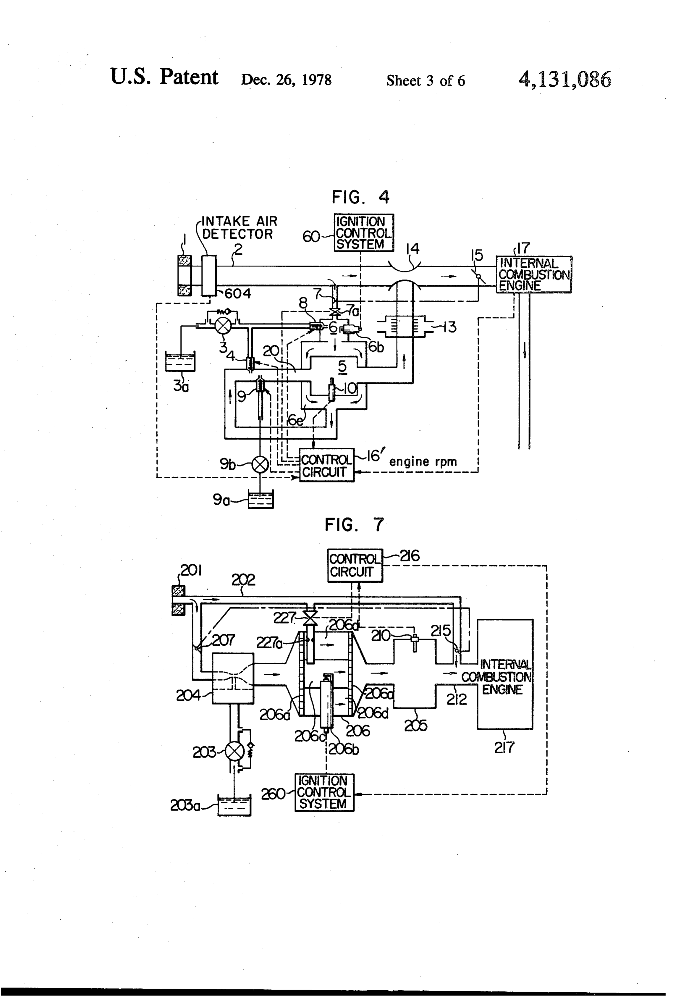
order to overcome these problems, according to the FIGS. 8 and 9 are schematic diagrams of a first and present invention, hydrocarbon fuel is mixed with the second variations thereof, combustion gases from the burning chamber down Similar reference numerals are used to designate simi stream thereof so that the hydrocarbon fuel may be lar parts throughout the figures.
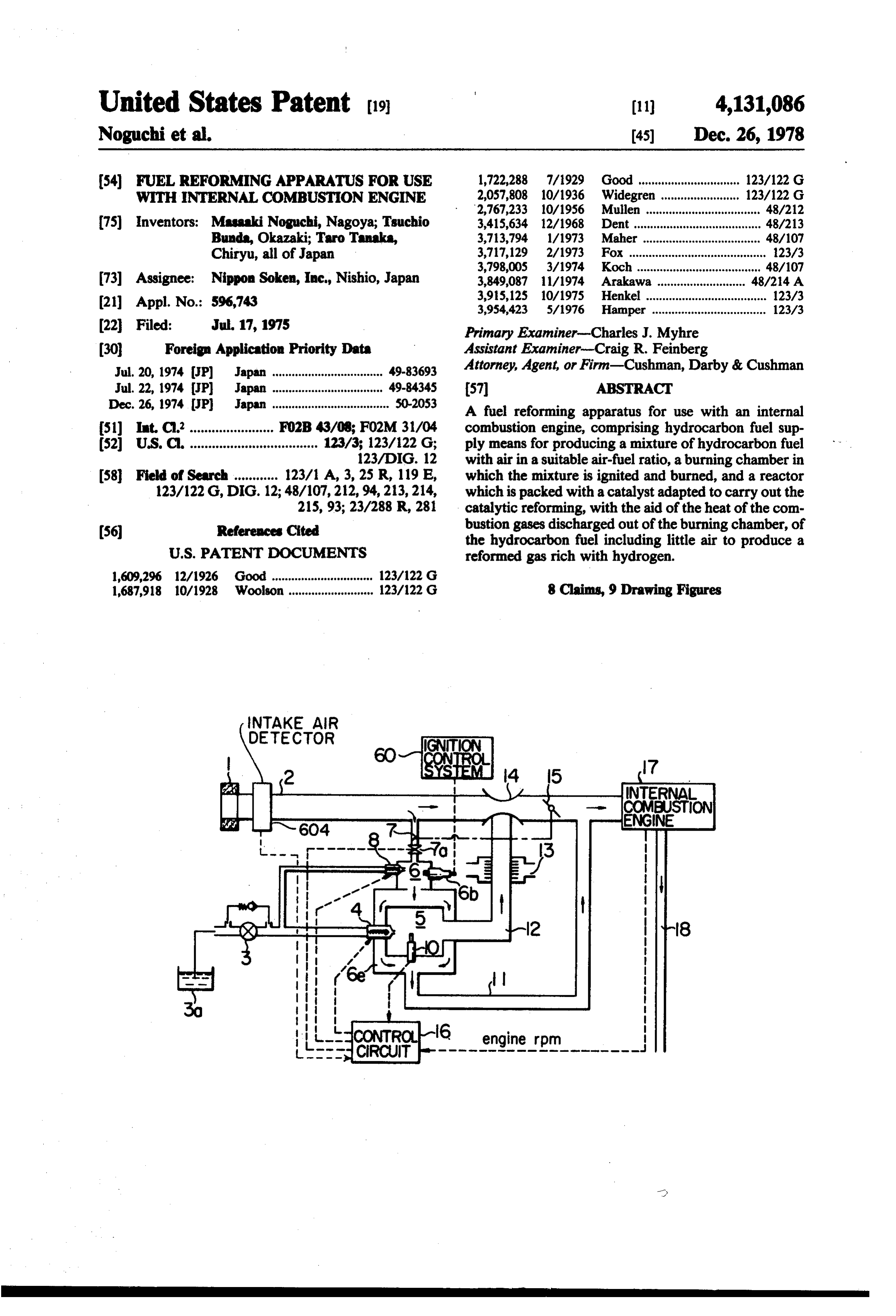
prevented from being directly exposed to the combus DESCRIPTION OF THE PREFERRED tion flames and may be uniformly mixed with the com EMBODIMENTS bustion gases before it is charged into the catalytic reac tor. First Embodiment, FIGS. 1 through 4 According to the present invention, the fuel reform ing process carried in the catalytic reactor causes essen 10 Referring to FIG. 1 illustrating a schematic diagram tially an endothermic reaction with little air or with of the first embodiment of a present invention, reference little oxygen being introduced into the catalytic reactor numeral 1 denotes an air filter for cleaning air to be so that thermal runaway may be prevented. Therefore, charged into an internal combustion engine; 2, an air it is essential that a combustion mixture with a suitable intake;3, a fuel pump for pumping and feeding a hydro air-fuel ratio must be ignited and burned in the burning 15 carbon in a fuel tank3a under a predetermined pressure; chamber, and that hydrocarbon fuel must be charged 4, a fuel injection valve which is adapted to control a into the catalytic reactor in such a way that little oxy fuel injection under the control of a control circuit 16, gen or air may be introduced into the catalytic reactor. which will be described in detail hereinafter, in response It is preferable that the temperature of the endothermic to the operating conditions of the engine; that is, an reaction be maintained in a range between 500 and 800' 20 opening degree of a throttle valve, a rotational speed of C. In order to stabilize the reaction within the catalytic the engine, an intake air quantity, and so on; 5, a cata reactor, to relax the reaction conditions and to improve lytic reactor packed with a catalyst for effecting an the conversion efficiency, it is preferable to use a cata efficient and quick catalytic reformation of the fuel into lyst such as nickel, cobalt, chromium, platinum, rho a reformed gas containing a large quantity of hydrogen dium or the mixture thereof. Whatever the type of the 25 which may be easily ignited and burnt, the catalyst catalyst used, it is essential that the catalyst should con being nickel, chromium, rhodium, platinum, cobalt, and vert the hydrocarbon fuel into a reformed gas rich with mixtures thereof; 6, a burning chamber for supplying hydrogen. heat to a reactor 5 so that a catalyst reaction tempera As described above, according to the present inven ture therein may be maintained, a part of the hydrocar tion, a reformed gas rich with hydrogen may be ob 30 bon fuel and a part of the intake air being mixed in a tained, and the combustion of hydrogen is about 8 times suitable ratio and being burned without producing any as fast as that of conventional gasoline fuel so that the soot, the optimum air-fuel ratio being about 7 to 15 combustion efficiency in the internal combustion en when the hydrocarbon fuel is gasoline; that is, 0.5 to 1.0 gines may be much improved. More particularly, a lean in terms of the excess air ratio A, the above range being combustion mixture, which has been hitherto impossi 35 also applied to other hydrocarbon fuels, 6b, an ignition ble to ignite and burn in an internal combustion engine plug electrically connected to a conventional ignition with a carburetor, can be positively ignited and burned control system 60 including an interruptor, a coil and so so that toxic gas emission may be minimized and fuel on; 7, a butterfly valve interlocked with a throttle valve consumption may be considerably improved. As com 15 for controlling the quantity of the air to be charged pared with the fuel which is atomized and vaporized by into the burning chamber 6; 7a, a stop valve for inter conventional carburetors, the reformed gas may be rupting or reducing the charge of the air into the burn more evenly distributed among the cylinders of an en ing chamber gine because the reformed gas is completely in the form reactor 5 rises6abnormally when the temperature of the catalytic high; 8, a fuel injection valve of a gas. Therefore, toxic gas emission may be further which injects the hydrocarbon fuel into the burning minimized. Although conventional high-octane fuel 45 chamber 6 under the control of the control circuit 16; contains aromatic hydrocarbons and lead compounds 6e, a heat exchange chamber with which the catalytic which are harmful to persons, the reformed gas does not reactor 5 is heated by the heat of the combustion gases require any aromatic hydrocarbon and lead com discharged out of the burning chamber 6; 10, a tempera pounds, because the reformed gas itself changes into ture sensor for detecting the temperature of the catalyst high-octane fuel. Therefore, any hydro-carbon such as 50 within the catalytic reactor 5 so as to transmit the signal naphtha may be advantageously used. This means that to the control circuit 16 when the temperature of the the fuel may be selected from a wide range of various catalyst rises abnormally high in order to prevent an hydrocarbons.
abnormal temperature rise of the catalyst, thereby im
BRIEF DESCRIPTION OF THE DRAWING 55 proving the service life thereof; 11, a gas passage com FIG. 1 is a schematic diagram of a first embodiment municated with the air intake 2 for discharging the combustion gases from the burning chamber 6; 12, a of a fuel reforming apparatus in accordance with the reformed gas passage for introducing the reformed gas present invention;
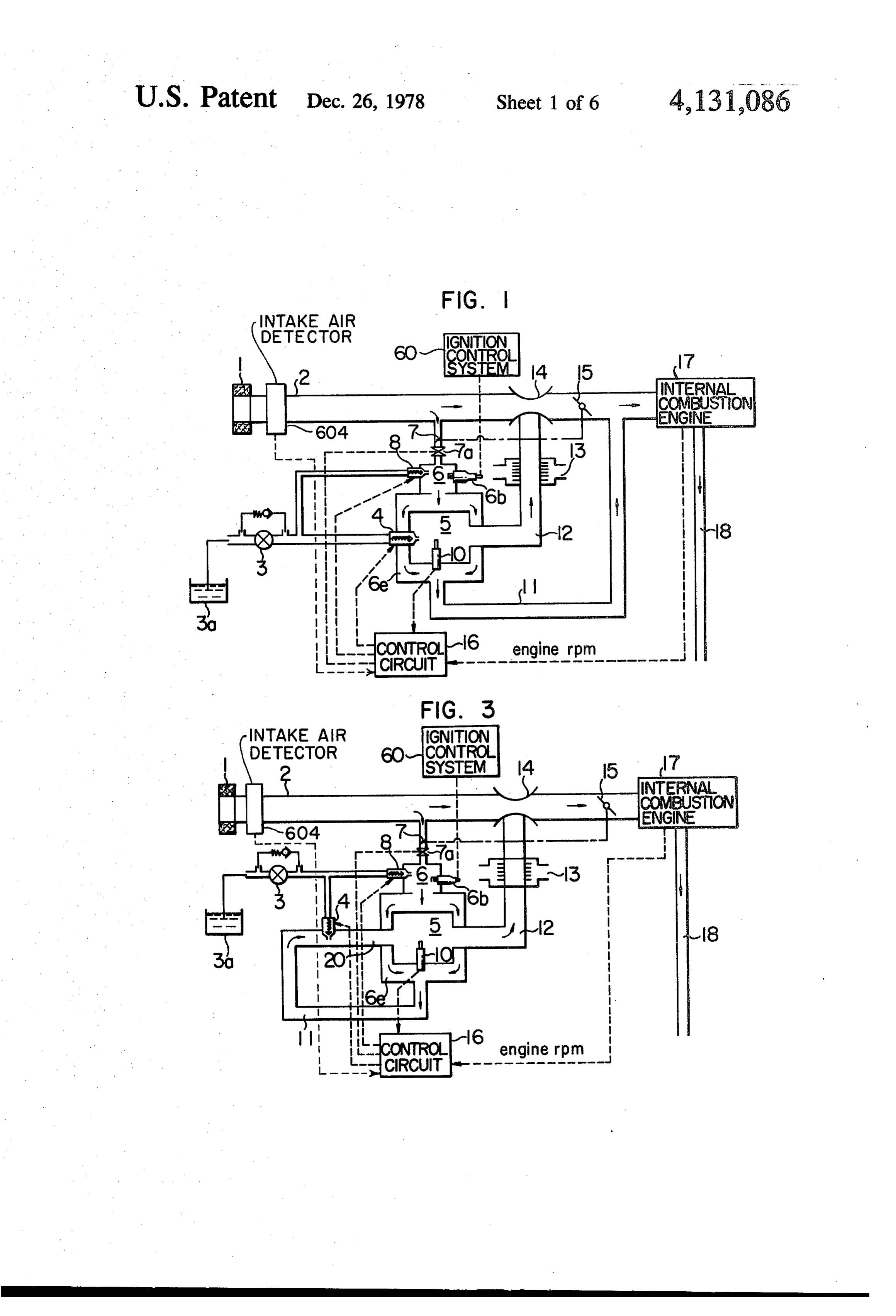
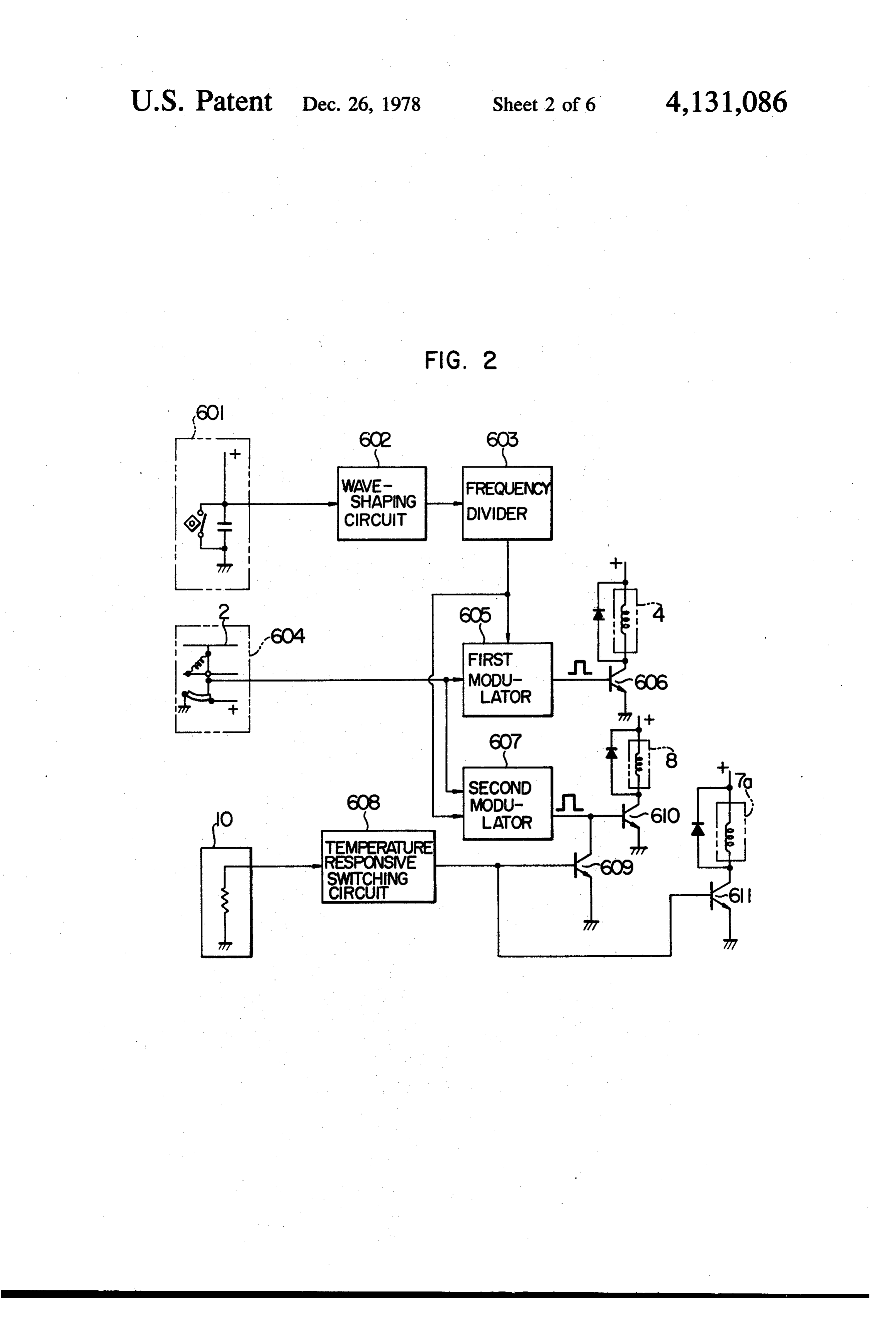
FIG. 2 is a block diagram of a control circuit (16) produced in the catalytic reactor 5 into the air intake 2; thereof; 13, a heat exchanger interposed in the reformed gas FIGS. 3 and 4 are schematic diagrams of a first and passage 12 for cooling reformed gas of a relatively high second variations of the first embodiment, respectively; temperature, air or cooling water of the engine being FIG. 5 is a schematic diagram of a second embodi used as the heat exchange medium; 14, a mixer inter ment of the present invention; posed within the air intake 2 for mixing the intake air FIG. 6 is a schematic diagram of one variation 65 with the reformed gas discharged out of the reformed thereof; gas pipe 12; 17, an internal combustion engine which FIG. 7 is a schemcatic diagram of a third embodiment may be of the stratified combustion or rotary type; and of the present invention; and 18, an exhaust pipe.
Page 10
FIG. 2 is a block diagram of the control circuit 16, fuel injection nozzle 8 is kept closed while the stop wherein reference numeral 601 denotes a reference valve 7a is also closed. This means that the supply of signal generator for generating a reference signal in both the fuel and air to the burning chamber 6 is inter synchronism with the rotation of the engine 17; 602, a rupted. Thus, the catalyst within the catalytic reactor 5 waveshaping circuit for shaping the reference signal may be prevented from being heated abnormally to from the reference signal generator 601; 603, a fre high temperatures, whereby the deterioration of the quency divider for dividing the frequency of the output catalyst may be prevented. The reformed gas produced reference signal from the waveshaping circuit 602; 604, in the reactor 5 is at relatively high temperatures, but an intake air detector for detecting the quantity of the may be cooled by the heat exchanger 13 in the reformed intake air to the engine 17; 605, a first modulator for 10 gas pipe 12 only to such an extent that condensation of calculating the injection timing and the injection time the reformed gas does not occur. The cooled reformed for the hydrocarbon fuel in response to the output sig gas is mixed in the mixer 14 in the air intake 2 with the nals from the frequency divider 603 and the intake air intake air, and the combustion mixture is charged into detector 604; 606, a power transistor used for control the cylinder in the engine 17. Because of the existence of ling the fuel injection valve 4 in response to the control 15 hydrogen within the reformed gas, the combustion of signal from the first modulator 605; 607, a second modu the lean mixture is possible. lator for calculating the fuel injection timing and injec tion time of the fuel injection valve 8 of the combustion tion gases from the exchange
Within the heat burning chamber 6e, the combus chamber 6 sufficiently heat chamber 6 in response to the output signals from the the catalytic reactor 5 and then are charged frequency divider 603 and the intake air detector 604; 20 intake 2 at downstream of the throttle valveinto 15. the air 608, a temperature responsive switching circuit which, in response to the output signal from the temperature First Variation of First Embodiment, FIG. 3 sensor 10, generates a high- or H-level signal when the In the first embodiment described so far with refer detected temperature is in excess of a predetermined ence to FIGS. 1 and 2, the combustion gases from the level, or a low- or L-level signal when the detected 25 temperature is lower than a predetermined level; 609, a burning chamber 6 have been described as being intro transistor for interrupting the transmission of the output variation discharged duced or of the first into the air intake 2, but in the first embodiment shown in FIG. 3, the control signal from the second modulator 607 in re combustion gases discharged sponse to the high- or H-level signal from the tempera chamber 6e are charged into out of the heat exchange ture responsive switching circuit 608; 610, a power order to improve the catalytic reformationreactor
of the
transistor used for controlling the fuel injection valve 8 drocarbon fuel in the catalytic reactor 5. For this pur in response to the output control signal from the second pose the combustion gas pipe 11 is opened into the 607; and 611, a transistor which is conducted in re catalytic reactor 5, and the fuel injection valve 4 is sponse to the high level signal from the temperature opened into the combustion gas pipe 11. responsive switching circuit 608, thereby closing the 35 In the instant embodiment, the catalytic reformation stop valve 7a, proceeds in the catalytic reactor as follows: Next the mode of operation of the fuel reforming apparatus with the above construction will be de scribed. The hydrocarbon fuel, which is fed under a predetermined pressure by the fuel pump 3 from the CmHn+ mH.oet, H, + mCO (1) fuel tank 3a to the fuel injection valve 4, is injected in a CmHn+ moo : H2 + 2mCO controlled quantity into the catalytic reactor 5 by the fuel injection valve 4 which is controlled in response to the control signal from the control circuit 16. The air where Q = heat.
introduced into the burning chamber 6 is controlled in 45 For instance, in the case of a hydrocarbon fuel having quantity by the butterfly valve 7 interlocked with the an average molecular formula throttle valve 15 so that the air in a predetermined ratio with respect to the intake air into the engine 17 may be CH fed into the burning chamber 6. The hydrocarbon fuel charged into the burning chamber 6 is also controlled 50 the following reactions in the burning chamber 6 and by the fuel injection valve 8 which in turn is controlled the catalytic reactor 5 are most advantageous for re by the control circuit 16. Thus the air-fuel mixture in a forming one mol. of hydrocarbon fuel CH11: suitable ratio is ignited by the ignition plug 6b and burned in the burning chamber without producing any 0.36CH1 + 3.5 (O2 + 3.76N2) = 2.51CO + soot, and the catalyst in the reactor 5 is heated by the 55 1.97HO + 13.16N, heat of the combustion gases discharged from the burn ing chamber 6, whereby the temperature of the catalyst in the burning chamber 6, and may be maintained within a suitable reaction tempera 0.64C7H1 + 2.51CO2 + 1.97HO + 13.16N = ture range. Thus, the catalytic reformation of the hy 7CO + 5.5H2 + 13.16N2 drocarbon fuel proceeds in the catalytic reactor 5 so that reformed gas including a large quantity of hydro in the catalytic reactor 5.
gen may be obtained. Since the catalytic reformation is From the above reaction formulae, the ratio of the essentially an endothermic reaction, thermal runaway fuels may be prevented. Even when an abnormal tempera lytic charged reactor 5 into the burning chamber 6 and the cata is about 1:2. Up to a maximum ratio of ture rise should occur in the catalytic reactor 5, the 65 1:1, the combustion efficiency may be improved by output signal from the temperature responsive switch charging the reformed gas, but when the ratio exceeds ing circuit 608 changes to the H-level in response to the 1:1, the fuel consumption as well as the contents of H2O output signal from the temperature sensor 10 so that the
Page 11
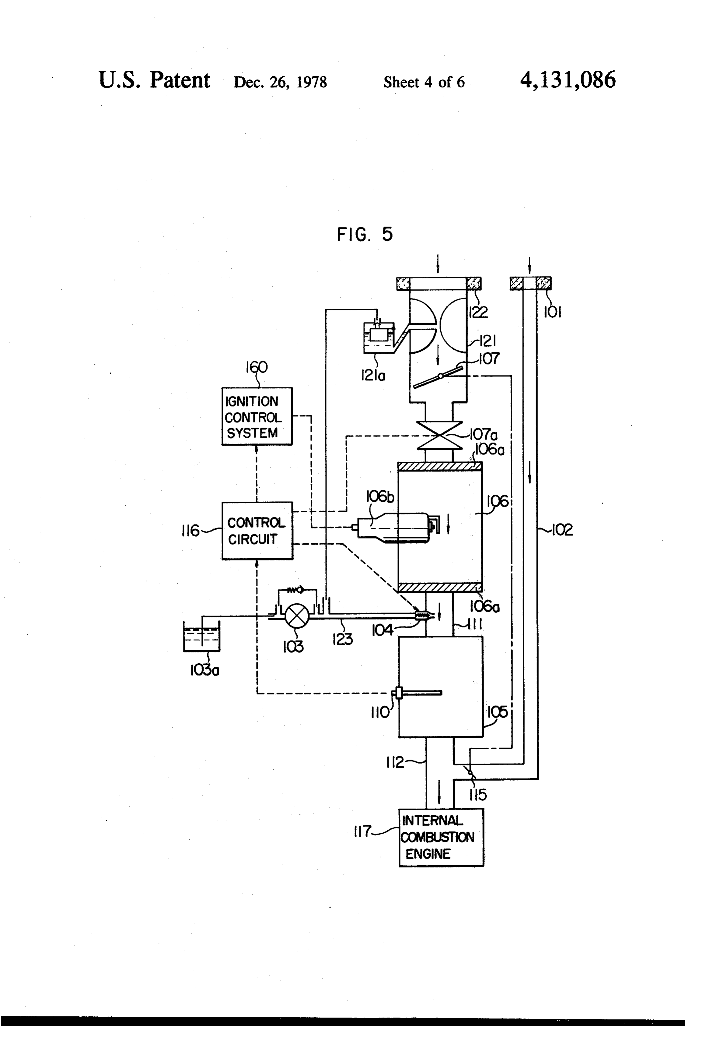
and CO2 in the reformed gas are increased disadvanta quantity of the combustion mixture may be introduced geously. Both the fuel injection valve 4 and 8 are so into the burning chamber 106; 121, a carburetor with a adjusted as to meet the above conditions. The advan float chamber 121a, 122, an air filter attached to the tage of the first variation over the first embodiment inlet of the carburetor 121; 110, a temperature sensor for resides in the fact that the production of carbon in the detecting the temperature within the reactor 105 so as catalytic reformation may be considerably suppressed, to obtain the temperature of the catalyst therein as in whereby the service life of the catalyst in the catalytic the case of the first embodiment, 111, a combustion gas reactor 5 may be remarkably improved. passage or pipe for discharging the combustion gases The control circuit 16 of the first variation is substan produced in the burning chamber 106 into the catalytic tially similar in construction to that of the first embodi reactor 105, the fuel injection valve 104 adapted to be
ment shown in FIG. 2, but it will be understood that the opened into this combustion gas pipe 111; 112, a re control circuit 16 operates a stop valve 7a in response to formed the output signal from the temperature sensor 10, when throttle gas pipe joined to the air intake 102; 115, the valve of an engine 117; and 116, a control cir the temperature within the catalytic reactor 5 exceeds a predetermined value, so that the stop valve reduces the 15 cuit substantially similar in construction and operation flow rate of the air flowing into the burning chamber, to the control circuit 16 shown in FIG. 2 for controlling thereby the catalyst is prevented from reaching an ab the fuel injection valve 104 and a stop valve 10ia in normal temperature. response to the operating conditions of the engine i 17. Next the mode of operation of the second embodi
Second Variation of First Embodiment, FIG. 4 20 ment with the above construction will be described. Air The second variation shown in FIG. 4 is substantially is taken into the air intake 102 through the air filter 30, similar in construction to the first variation shown in and the combustion mixture with a suitable ratio pro FIG. 3 except that the water pumped up by a water duced in the carburetor 121 is charged into the burning pump 9b from a water storage tank 9a is injected chamber 106 where the combustion mixture is ignited through a water injection nozzle 9 into the catalytic 25 by the ignition plug 106b and burned. The combustion reactor 5. The water injection nozzle 9 is controlled in products produced in the burning chamber 106 as well response to the control signal from the control circuit as the hydrocarbon fuel from the fuel tank iC3a are 16. The second variation also has a distinct advantage charged into the reactor i05. The quantity of the hydro over the first embodiment shown in FiC. 1 in that the carbon fuel to be introduced into the reactor i05 is production of carbon in the catalytic reforming may be 30 controlled by the fuel injection valve 104 which in turn considersably suppressed. is controlled by the control circuit 116 in response to In the first embodiment and its first and second varia tions, the reformed gas has been described as being the signal representative of the intake air quantity. The major portion of the burning products from the con charged into the cylinders of the engine, but in the case bustion of the stratified combustion engine with an engine auxil 35 ide, and chamber oxygen is 106 consists of water and carbon diox almost excluded so that the hydrocar iary combustion chamber or trap chamber, only the bon fuel may be reformed by the catalytic reformation reformed gas or the relatively rich mixture of the re formed gas with air may be charged into the trap cham as indicated by the reaction formula (1) (See First Wari ber while the relatively lean mixture of the hydrocarbon ation). The catalytic reformation proceeds more favou fuel with air may be charged into the main engine com rably at the temperature range between 500 and 800' bustion chamber so that the reduction in the toxic con C. so that the quantity of the combustion mixture is pounds in the exhaust gases may be attained; sufficiently controlled by the butterfly valve 107 interlocked with strong power may be obtained; and the fuel consump the throttle valve 15, thereby controlling the reacting tion rate may be considerably improved. temperature within the above range. As in the case of 45 the first embodiment, when the temperature in the cata
Second Embodiment, FIG. 5 lytic reactor 105 exceeds a predetermined value, the The second embodiment shown in FIG. 5 is different control circuit 116 operates the stop valve 107a in re from the first embodiment shown in FIG. in that a sponse to the output signal from the temperature sensor carburetor 121 is provided in order to charge the com 110 so that the stop valve 107a reduces the flow rate of bustion mixture in an optimum ratio. In FIG. 5, refer 50 the combustion mixture flowing into the burning chain ence numeral 101 denotes an air filter; 02, an air intake; ber to a minimum value. The hydrogen rich reformed 103, a fuel pump; 103a, a hydrocarbon fuel storage tank; gas is charged into the engine 17, whereby the combus 104, a fuel injection valve substantially similar in con tion efficiency may be remarkably improved as is the struction and operation to the fuel injection valve case of the first embodiment.
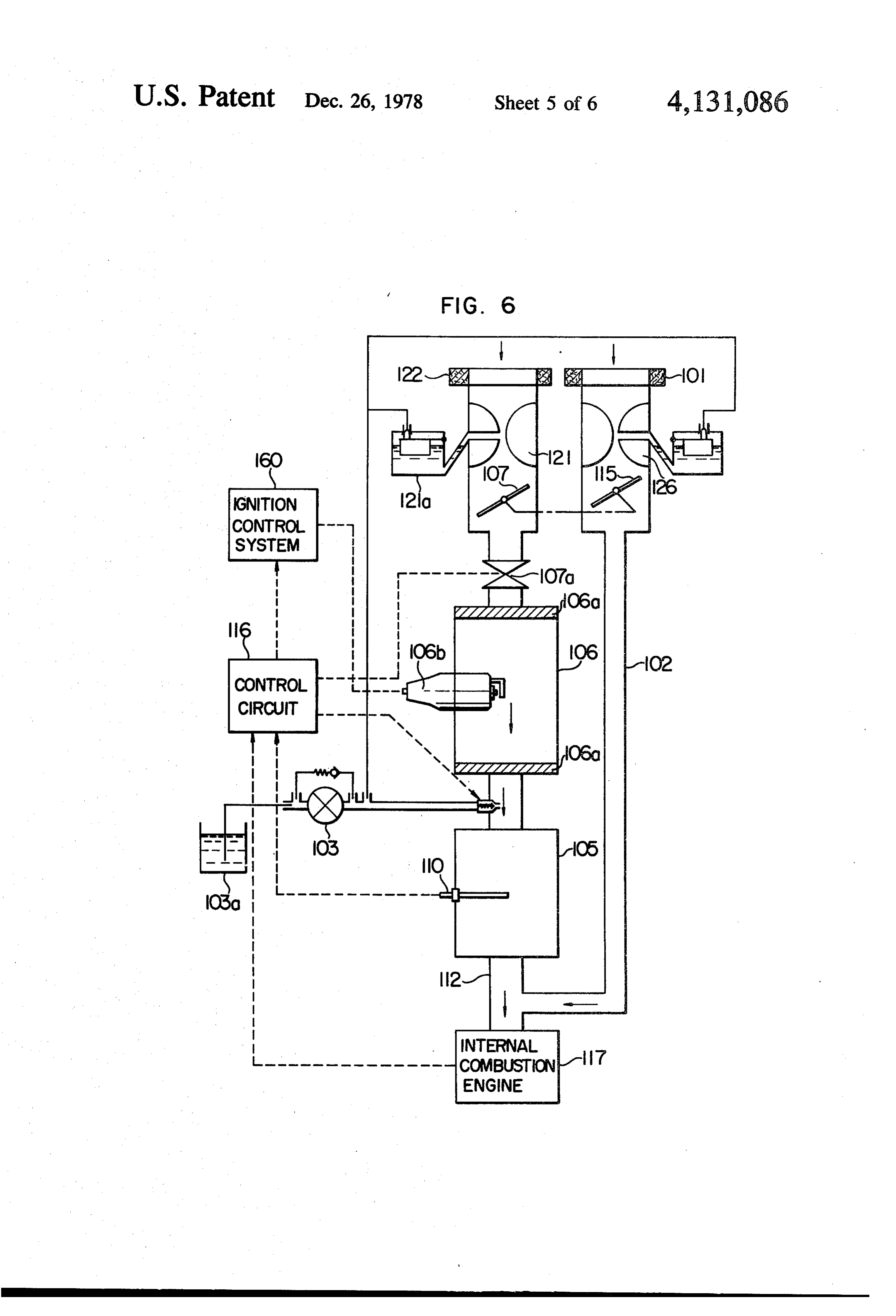
shown in FIG. 1; 105, a catalytic reactor packed with 55 the catalyst for catalytic reformation of hydrocarbon Variation of the Second Embodiment, FIG. 6 fuel; 106, a burning chamber with an ignition plug it6b In the second embodiment described so far with ref. electrically connected to an ignition control system 160 erence to FIG.S, only the reformed gas is charged into and two flame arresters 106a disposed at the inlet and the engine 117, but in the varation shown in FIG. 6 of outlet ends respectively; 107, a butterfly valve inter the second embodiment, both a relatively lean mixture locked with a throttle valve 15 for controlling the combustion mixture to be charged into the burning of the hydrocarbon fuel with air and reformed gas are chamber 106; 107a a stop valve disposed at the down charged into the engine 117. For this purpose, a carbu stream of the butterfly valve 107 and adapted to be retor 126 is inserted into the air intake 102. This varia actuated, when the temperature within the catalytic 65 tion has an advantage over the second embodiment in reactor 105 exceeds a predetermined value, in response that the engine output may be considerably improved as to a control signal from the control circuit 16 to be compared with the second embodiment in which only described in detail hereinafter so that only a minimum the reformed gas is charged into the engine.
Page 12
9 O
Third Embodiment, FIG. 7 tion plug 206b and burned. The excessively rich mixture charged into the outer chamber 206d is heated by the
In the first embodiment shown in FIG. 1 both the heat generated by the combustion within the inner duct catalytic reactor 5 and the burning chamber 6 are pro or the inner combustion chamber 206c as the mixture vided with the fuel injection valves 4 and 8, respec flows through the outer chamber 206d, and is then tively, but in the third embodiment shown in FIG. 7, charged into the catalytic reactor 205. In the catalytic both the fuel injection valves 4 and 8 are eliminated and reactor 205, into which are charged the heated exces instead a carburetor 204 is provided in order to simplify sively rich mixture and the combustion products from the construction of the fuel or hydrocarbon fuel supply the burning chamber 206, catalytic reformation is ef system. In FIG. 7, reference numeral 201 denotes an air O fected so that a reformed gas rich with hydrogen may filter; 202, an air intake; 203, a fuel pump; 203a, a fuel be produced. As in the case of the first and second tank; 204, a carburetor for mixing the air with the hy embodiments, the reformed gas is charged into the en drocarbon fuel to produce a rich mixture having an gine 217 for combustion.
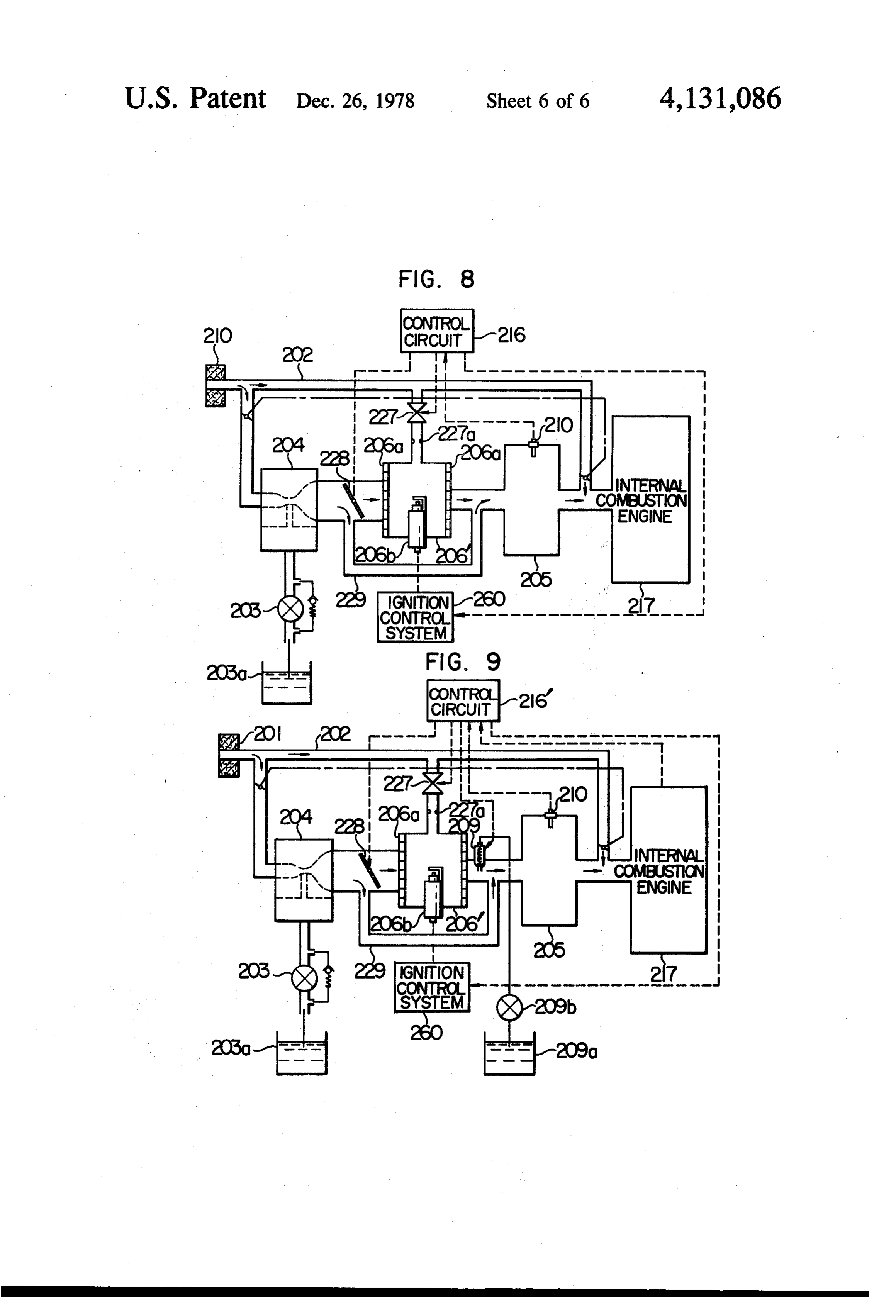
air-fuel ratio less than unity; 207, a butterfly valve inter When the temperature within the catalytic reactor locked with a throttle valve 215; 206, a burning cham 15 205 exceeds a predetermined temperature, in response ber consisting of an inner duct or an inner combustion to the output signal from the temperature sensor 210, chamber 206c and an outer chamber 206d formed con the control circuit 216 closes the stop valve 227, thereby centric with the inner combustion chamber 206c, the interrupting the supply of the air into the inner duct or relatively rich mixture, from the carburetor 204, being the inner combustion chamber 206c. thus, the combus mixed with air, ignited by an ignition plug 206b and 20 tion within the inner duct or the inner combustion burned within the inner duct or the inner combustion chamber 206c is stopped. It should be noted that even chamber 206c, whereby the combustion products when combustion is stopped, endothermic catalytic (water and carbon dioxide) and heat required for cata reforming proceeds within the catalytic reactor 205. lytic reformation may be obtained; 206a, flame arrestors disposed at the inlet and outlet of the burning chamber 25 First Variation of the Third Embodiment, FIG. 8 206; 227, a stop valve inserted in an air supply pipe to In the third embodiment described so far in conjunc the inner combustion chamber 206c. 227a, an orifice or tion with FIG. 7, the excessively rich mixture produced restrictor inserted in the air supply pipe so that the in the carburetor 204 is divided to flow into the inner quantity of the air to be charged into the inner duct or and outer chambers 206c and 206d in a ratio depending the inner combustion chamber 206c may be controlled upon the ratio between the inlet opening areas of the in response to the negative pressure in the inner com inner and outer chambers 206c and 206d, but in the first bustion chamber 206c. 205, a reactor packed with a variation shown in FIG. 8, a part of the excessively rich catalyst so that the catalytic reformation of the rich mixture flows through a by-pass pipe 229 of a burning mixture with almost no air supplied from the carburetor chamber 206, and then is mixed with the combustion 204 may be effected by the heat of the combustion prod 35 gases discharged from the burning chamber 206 before ucts produced in the burning chamber 206 and intro it is charged into the catalytic reactor 205. In order to duced into the catalytic reactor 205; 210, a temperature control the ratio between the excessively rich gas sensor for detecting the temperature within the reactor charged into the burning chamber 206 and the exces 205; 216, a control circuit for controlling a stop valve sively rich mixture flowing through the by-pass line 227 and an ignition control system 260 in response to the 229, a switching valve 228, which is controlled in re output signal from the temperature sensor 210, the sponse to the output control signal from the control mode of operation of the control circuit 216 being sub circuit 216, is provided. The switching valve 228 may stantially similar to that of the first embodiment; the be of the conventional type consisting of a solenoid ignition control system 260 being also similar in con operated valve and a butterfly valve. struction and mode of operation to that of the first em 45 When the temperature in the catalytic reactor 205 bodiment; and 212, a reformed gas pipe leading to an rises in excess of a predetermined level, the switching engine 217 and joined to the air intake 202 downstream valve 228 is so actuated that almost all of the excessively of the throttle valve 215 inserted therein. rich mixture produced in the carburetor 204 is made to Next the mode of operation of the third embodiment flow through the by-pass line 229 so as to be directly with the above construction will be described. In re 50 charged into the catalytic reactor 205. At the same time, sponse to the opening degree of the butterfly valve 207 the stop valve 227 is so actuated as to reduce the flow which is interlocked with the throttle valve 215, the rate of the air flowing into the burning chamber. quantity of the intake air to be charged into the carbure Second Variation of the Third Embodiment, FIG. 9 tor 204 is controlled. In response to the quantity of the air charged into the carburetor 204, the quantity of the 55 The second variation of the third embodiment shown hydrocarbon fuel to be charged into the carburetor 204 in FIG. 9 is substantially similar in construction to the is also controlled so that the excessively rich combus first variation shown in FIG. 8 except that the water tion mixture with an air-fuel ratio of less than unity may from a water storage tank. 209a is injected into the com be produced and charged into the burning chamber 206. bustion gases discharged out of the burning chamber The combustion mixture charged into the inner and 206 by a water pump 209b and a water injection nozzle outer chambers 206c and 206d is divided in a ratio de 209, which is controlled in response to the output con pending upon the ratio between the inlet opening areas trol signal from the control circuit 216 as in the case of of the inner and outer chambers 206c and 206d. The the second variation shown in FIG. 4 of the first em excessively rich combustion mixture charged into the bodiment. Since water is injected, even when the quan inner duct or the inner combustion chamber 206c is 65 tity of combustion gases is less, the production of car further mixed with air charged therein through the air bon within the catalytic reactor 205 may be considera supply pipe to the relatively lean combustion mixture bly reduced as compared with the first variation shown with a suitable air-fuel ratio, and is ignited by the igni in FIG. 8. Furthermore, the chemical energy loss may
Page 13
be minized, and the content of hydrogen in the re 2. A fuel reforming apparatus as set forth in claim 1, formed gas may be considerably increased. further comprising,
What we claim is: a spark plug disposed in said burning chamber for 1. In an internal combustion engine including an en igniting said charge of air and a fuel. gine combustion chamber, an intake pipe for supplying 5 3. A fuel reforming apparatus as set forth in claim 1, at least air to said engine combustion chamber, and a further comprising:
throttle valve pivotally disposed in said intake pipe for temperature detecting means for detecting the tem controlling the amount of air passing therethrough, perature of said catalytic reactor and actuating said a fuel reforming apparatus for supplying a reformed charging means to stop the charge of air and fuel gas including hydrogen and carbon monoxide to 10 when the detected temperature exceeds a predeter said engine combustion chamber of said internal mined value.
combustion engine comprising: 4. A fuel reforming apparatus as set forth in claim 1, (i) a burning chamber for substantially burning a further comprising:
charge of air and a hydrocarbon fuel therein, to temperature detecting means for detecting the tem thereby produce heat and combustion gas; 15 perature of said catalytic reactor and actuating said (ii) means coupled to said burning chamber for charging means to stop the charge of air when the charging in said burning chamber said charge of temperature of said catalytic reactor exceeds a air and a fuel and controlling the amount of said predetermined value.
charge of air and a fuel in response to the amount 5. A fuel reforming apparatus as set forth in claim 1, of air passing through said intake pipe; 20 further comprising:
(iii) a catalytic reactor having therein a catalyst for water supply means for supplying water to said cata reforming hydrocarbon fuel into a reformed gas lytic reactor to facilitate reforming reaction in said including hydrogen and carbon monoxide, said catalytic reactor.
catalytic reactor being communicated with said 6. A fuel reforming apparatus as set forth in claim 1 burning chamber so that said combustion gas 25 further comprising a heat exchanger disposed in said from said burning chamber is introduced into communicating means and so arranged as to cool said said catalytic reactor; reformed gas discharged out of said catalytic reactor. (iv) means for supplying at least a hydrocarbon fuel 7. A fuel reforming apparatus as set forth in claim 1 to said catalytic reactor to reform said hydrocar wherein the quantity of said hydrocarbon fuel charged bon fuel into the reformed gas with the aid of 30 into said burning chamber is so controlled as to be less said heat, combustion gas and catalyst, through than the quantity of said hydrocarbon fuel charged into an endothermic reaction in said catalytic reactor; said catalytic reactor.
and 8. A fuel reforming apparatus as set forth in claim 7 (v) means communicating said catalytic reactor wherein the ratio between the hydrocarbon fuel with said engine combustion chamber of said 35 charged into said burning chamber and the hydrocar internal combustion engine for introducing said bon fuel charged into said. catalytic
reactor is about 1:2.
reformed gas thereto.
Provenance
- Collection
- Cited prior art
- Original PDF
- patentimages.storage.googleapis.com →
- Filed
- 1975-07-17
- Pages
- 13
- Method
- pdftotext (the PDF's own text layer) + pdftoppm 300dpi page scans
- Source
- Google Patents bibliographic record
- Granted
- 1978-12-26
- Inventors
- Masaaki Noguchi; Tsuchio Bunda; Taro Tanaka; Nippon Soken Inc
- Transcribed from
- patentimages.storage.googleapis.com →