patent · US4573435
Apparatus and method for generating hydrogen gas for use as a fuel additive in diesel engines
4 March 1986
Page 1 — bibliographic record
United States Patent (19) 11) Patent Number: 4,573,435 Shelton 45) Date of Patent: Mar. 4, 1986 (54) APPARATUS AND METHOD FOR Primary Examiner-Ira S. Lazarus GENERATING HYDROGEN GAS FOR USE Attorney, Agent, or Firm-Charles R. Rhodes; Judith E. ASA FUEL ADDITIVE IN DESEL ENGINES Garmon -
76) Inventor: Glenn F. Shelton, Rte. 1, Box 333,
Lawsonville, N.C. 27022 (21) Appl. No.: 749,733 Water is sprayed onto the surface of a bank of conduits or tubes extending through a heat exchange compart 22 Filed: Jun. 28, 1985 ment, which conduits carry the hot exhaust gases from a diesel engine at a temperature of approximately
Related U.S. Application Data 950-1100" F. The water is sprayed at such a rate that a 63) Continuation-in-part of Ser. No. 710,718, Mar. 12, substantial portion of the water is reformed into a mix 1985. ture of hydrogen and oxygen gas and steam. The hydro (51) Int. Cl. .............................................. FO2B 43/10 gen is then mixed with air to form hydrogen enriched (52) U.S. C. ............................... 123/3; 123/DIG. 12; air which is introduced into the combustion chamber. 123/1 A; 123/25 P When the hydrogen enriched air is compressed, the 58) Field of Search .................. 123/DIG. 12, 1 A, 3, diesel fuel is introduced with a resulting improvement 123/25 B, 25C, 25 D, 25 P in fuel efficiency and maximized combustion of the fuel.
The water is delivered to the hydrogen generator re sponsive to the activation of the accelerator pedal at a
4,003,343 1/1977 Lee ............................ 123/DIG. 2 diesel fuel is substantially in the range of 5% to 10%. 4,009,006 2/1977 Hreha...................................... 123/3 Air from the engine turbosupercharger is delivered to 4,030,453 6/1977 Sugimoto ..... 123/25 P the hydrogen generator to pick up and carry the hydro 4,036, 181 7/1977 Matovich ................................ 123/3 gen gas back to the air intake of the engine. Both the 4,037,568 7/1977 Schreiber ................................ 123/3 diesel fuel and water may be preheated to maximize 4,114,566 9/1978 Harpman et al. ....................... 123/3 results.
4,380,970 4/1983 Davis .......................... 123/DIG. 12 15 Claims, 4 Drawing Figures
2O ACCELERATOR
SWITCH
AIR
INTAKE
MANEFOLD
EXHAUST
FROM EXHAUST
ENGINE 64 SYSTEM
Page 2
Drawing sheet — no readable text.
Page 3
Drawing sheet — no readable text.
Page 4
APPARATUS AND METHOD FOR GENERATING
a thermal reactor, with hydrogen gas produced along
HYDROGEN GAS FOR USE ASA FUEL ADDITIVE
with varying amounts of hydrocarbon by-products.
IN DESEL ENGINES While prototypes have been developed, extensive size reduction and improvement will be necessary before
REFERENCE TO RELATED APPLICATIONS commercialization is realized. Further, such approaches are inherently disadvantageous in that a portion of the
The present invention is a continuation-in-part of petroleum fuel, which is attempted to being saved, is application Ser. No. 710,718 filed Mar. 12, 1985 in the utilized in the reforming process and therefore lost as name of Glenn F. Shelton. 10 the primary fuel.
BACKGROUND OF THE PRESENT INVENTION Another approach to the on-board generation of hy drogen
It has been recognized for many years that the use of transformed is the steam-over-iron process, in which water is hydrogen gas as a primary fuel, supplemental fuel, or or filings. The into steam, and then passed over iron flakes fuel additive, either alone in addition to petroleum base gas from the steam iron filings tend to remove the oxygen fuels offers distinct advantages for the operation of hydrogen gas for usage by an oxidation process, leaving the internal combustion engines, particular in light of in Examples of this approachasare a fuel or fuel supplement. described in the patents creased fuel costs, limited supplies, and environmental to Harrel, U.S. Pat. No. 1,966,345 and Kelly, U.S. Pat. concerns. The hydrogen gas not only provides fuel efficiencies and economies, but when used with petro that No. 4,256,060. It is recognized in both of these patents elum base fuels also inherently causes them to burn 20 filingsperiodic cleaning or changing of the iron flakes or is necessary in order to keep this technique oper more completely, thus minimizing and at times con ative.
pletely eliminating the contaminating pollutants in the gases exhausted to the atmosphere. In general, prior art disclosures indicate that the en The main effort towards the development of practical gine exhaust heat alone is either insufficient, cannot be usage of hydrogen as a fuel for internal combustion 25 kept hot enough, or enough heat therefrom cannot be engines has been by way of the storage of hydrogen gas transferred to the water to liberate hydrogen therefrom. on board the vehicle as the primary fuel source. The Of all prior art references known to applicant concern most prominent method used for the storage of the gas ing the on-board generation of hydrogen, only two has been the utilization of various types of metal hy have been located with are directed to the generation of drides, which act as hydrogen gas sponges to absorb 30 hydrogen from water utilizing primarily a direct heat and release the gas as required. exchange process. These references are U.S. Pat. Nos. Several large business entities such as Brookhaven 4,030,453 to Sugimoto, and 4,380,970 to Davis. In the Labs, Billings Corporation, and Mercedes Benz have Sugimoto disclosure, the water undergoes a three step adopted such on-board hydrogen storage techniques, heat exchange process, with the final step of the heat however, while such techniques are attractive for many 35 exchange taking place in the engine block itself. Thus, a internal combustion engine applications there remains complete redesign of the engine block is necessary and the problem of converting engines to those primarily from a commercial standpoint is not likely to receive operated by hydrogen fuel and the problems of distrib immediate widespread acceptance. The Davis patent uting hydrogen to the consuming public. For these also reasons, it is felt that such an approach is years away 40 thereutilizes
a quite complicated technique in which provided a disassociation chamber in the form from implementation on a commercial scale.
Further, approaches which involve the on-board of a transition tube carrying a copper spiral ribbon adja cent the engine manifold through which the water (or storage of hydrogen are not initially attractive to a large steam passes) in order that it be heated sufficiently to portion of the users of internal combustion engines, disassociate to its constituent gases hydrogen and oxy because hydrogen is considered dangerous to store and 45 gen. This also is a relatively expensive undertaking handle.
Considerable further efforts have been expended involving considerable changes to the engine itself and toward utilizing hydrogen as a supplemental fuel which cannot be easily implemented.
may be generated on board in small amounts and used In order to realize early and wide range acceptance, immediately, so that the storage problem does not exist. 50 it is believed that a system utilizing hydrogen as a sup One such approach deals with heat recovery from the plemental fuel or fuel additive must be relatively inex engine exhaust manifolds to drive various types of pensive; be capable of retrofitting existing engines; be closed cycle engine loops, which in turn are used to compatible with internal combustion engines without provide a low voltage DC power source required for substantial alteration of the engine or engine block; be electrolysis cells which will generate hydrogen from a 55 capable of on-board generation of hydrogen, and the water source. The major problem with the electrolysis hydrogen must be generated by means of a heat ex approach is that a very large electrical wattage is re change technique.
quired to reform the water into its constituent elements, SUMMARY OF THE PRESENT INVENTION and the amounts of such energy which can be generated from the exhaust manifold heat has, for the most part, 60 The present invention relates in general to the im proven insufficient to provide an ample flow of hydro provement of fuel consumption in at least a diesel type gen. Therefore, these approaches generally require internal combustion engine (and is believed to be adapt additional sources of electrical energy in order to be able for gasoline fuel engines). Particularly the present operative, and such additional sources of energy (such invention relates to a method and apparatus for generat as additional batteries) are extremely expensive. 65 ing hydrogen from water for use as a fuel additive by a Another on-board hydrogen generation technique is unique technique in which the water is passed in heat the reforming of gasoline in which a small flow volume exchange relationship to the hot exhaust gases of the of gasoline is broken down into its basic components in diesel engine at a point remote from the engine.
Page 5
In accordance with the present invention there is and at such a rate that the hydrogen may be utilized as provided a technique (both method and apparatus) for a fuel additive to substantially increase the rate of fuel improving the fuel economy and emission quality of a consumption and maximize the combustion of the fuel. diesel engine wherein water is delivered from a pressur Other objects and a fuller understanding will become ized water source to the water inlet of the heat ex apparent from reading the following detailed descrip changer (hydrogen generator) at a controlled rate de tion of a preferred embodiment along with the accom termined by the delivery of diesel fuel to the diesel panying drawings in which:
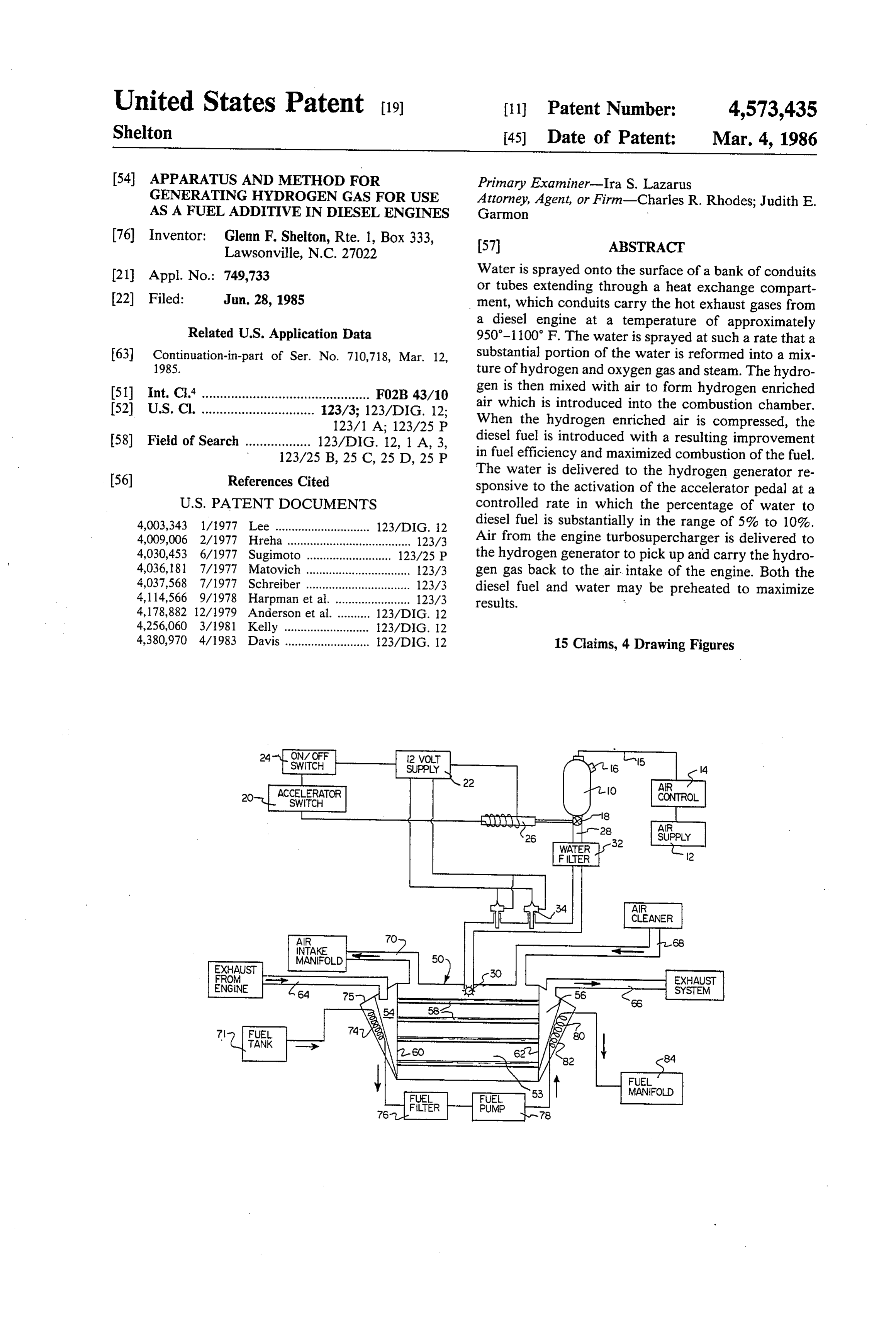
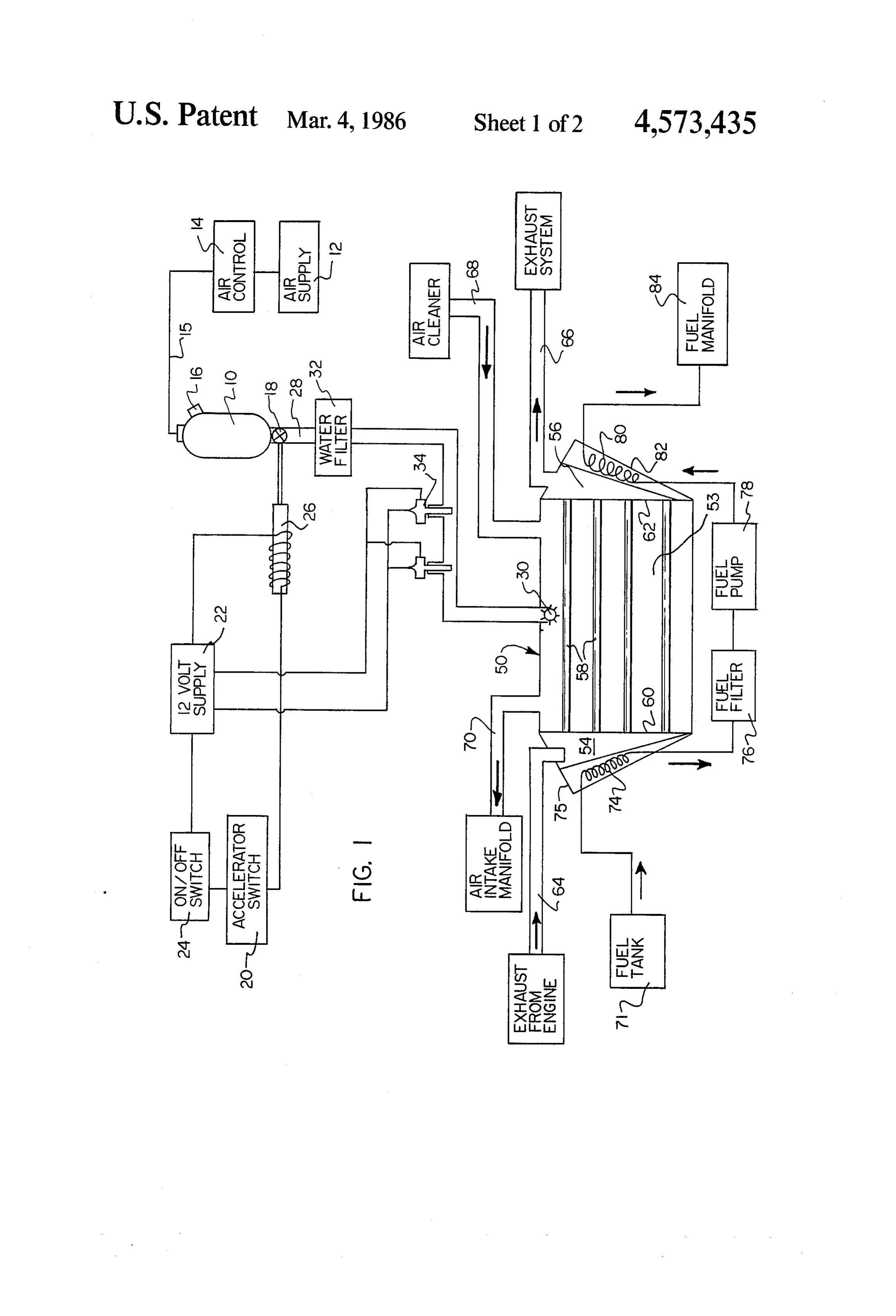
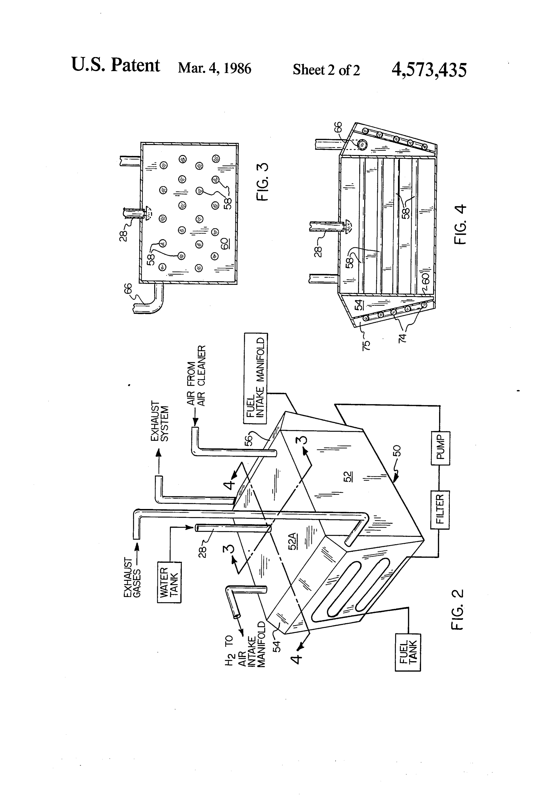
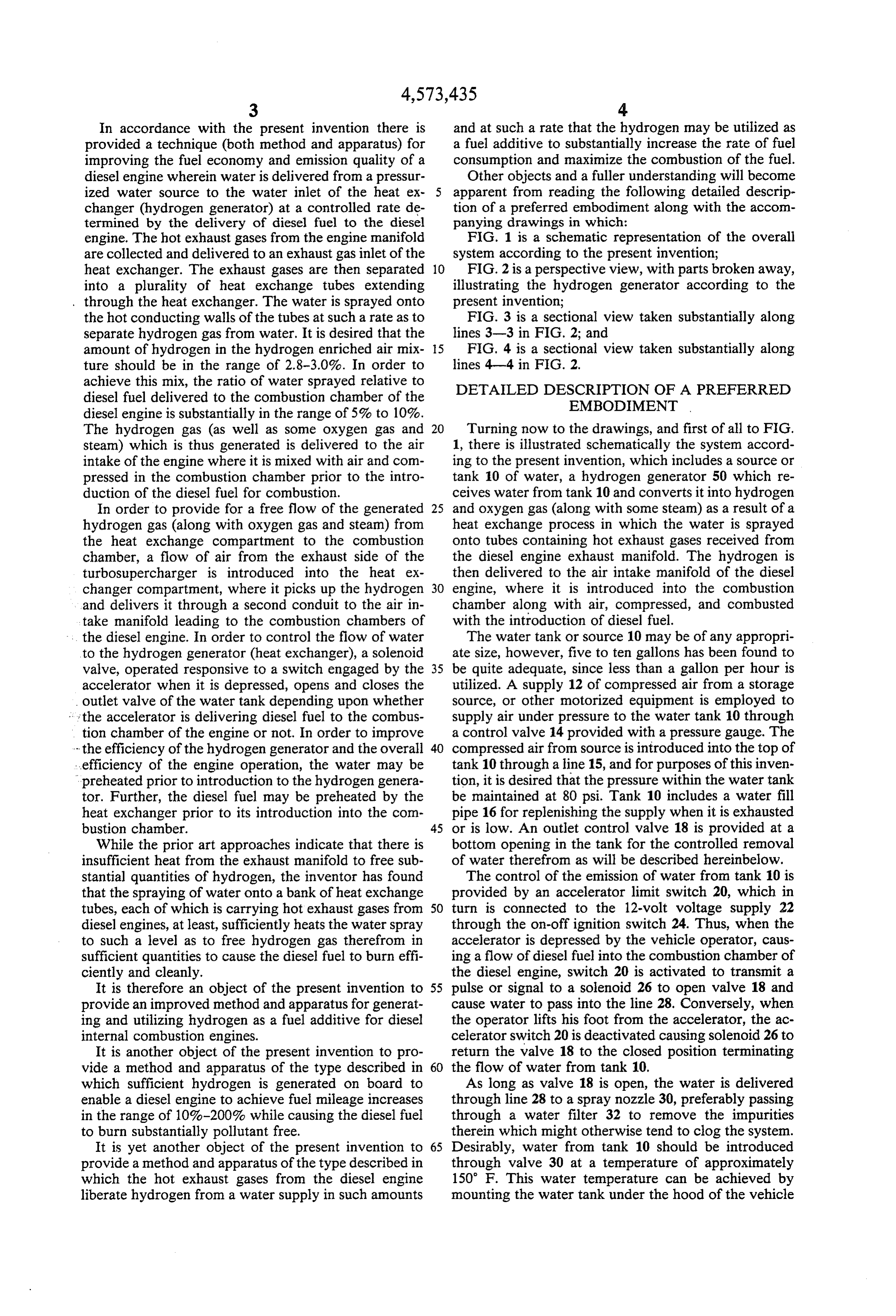
engine. The hot exhaust gases from the engine manifold FIG. 1 is a schematic representation of the overall are collected and delivered to an exhaust gas inlet of the system according to the present invention; heat exchanger. The exhaust gases are then separated 10 FIG. 2 is a perspective view, with parts broken away, into a plurality of heat exchange tubes extending illustrating the hydrogen generator according to the , through the heat exchanger. The water is sprayed onto present invention;
the hot conducting walls of the tubes at such a rate as to FIG. 3 is a sectional view taken substantially along separate hydrogen gas from water. It is desired that the lines 3-3 in FIG. 2; and amount of hydrogen in the hydrogen enriched air mix 15 FIG. 4 is a sectional view taken substantially along ture should be in the range of 2.8-3.0%. In order to lines 4-4 in FIG. 2.
achieve this mix, the ratio of water sprayed relative to DETAILED DESCRIPTION OF A PREFERRED diesel fuel delivered to the combustion chamber of the diesel engine is substantially in the range of 5% to 10%. EMBODIMENT . The hydrogen gas (as well as some oxygen gas and 20 Turning now to the drawings, and first of all to FIG. steam) which is thus generated is delivered to the air 1, there is illustrated schematically the system accord intake of the engine where it is mixed with air and com ing to the present invention, which includes a source or pressed in the combustion chamber prior to the intro tank 10 of water, a hydrogen generator 50 which re duction of the diesel fuel for combustion. ceives water from tank 10 and converts it into hydrogen In order to provide for a free flow of the generated 25 and oxygen gas (along with some steam) as a result of a hydrogen gas (along with oxygen gas and steam) from heat exchange process in which the water is sprayed the heat exchange compartment to the combustion onto tubes containing hot exhaust gases received from chamber, a flow of air from the exhaust side of the the diesel engine exhaust manifold. The hydrogen is turbosupercharger is introduced into the heat ex then delivered to the air intake manifold of the diesel changer compartment, where it picks up the hydrogen 30 engine, where it is introduced into the combustion and delivers it through a second conduit to the air in chamber along with air, compressed, and combusted take manifold leading to the combustion chambers of with the introduction of diesel fuel.
... the diesel engine. In order to control the flow of water The water tank or source 10 may be of any appropri to the hydrogen generator (heat exchanger), a solenoid ate size, however, five to ten gallons has been found to valve, operated responsive to a switch engaged by the 35 be quite adequate, since less than a gallon per hour is accelerator when it is depressed, opens and closes the utilized. A supply 12 of compressed air from a storage outlet valve of the water tank depending upon whether source, or other motorized equipment is employed to : the accelerator is delivering diesel fuel to the combus supply air under pressure to the water tank 10 through tion chamber of the engine or not. In order to improve a control valve 14 provided with a pressure gauge. The - the efficiency of the hydrogen generator and the overall 40 compressed air from source is introduced into the top of efficiency of the engine operation, the water may be tank 10 through a line 15, and for purposes of this inven preheated prior to introduction to the hydrogen genera tion, it is desired that the pressure within the water tank tor. Further, the diesel fuel may be preheated by the be maintained at 80 psi. Tank 10 includes a water fill heat exchanger prior to its introduction into the com pipe 16 for replenishing the supply when it is exhausted bustion chamber. 45 or is low. An outlet control valve 18 is provided at a While the prior art approaches indicate that there is bottom opening in the tank for the controlled removal insufficient heat from the exhaust manifold to free sub of water therefrom as will be described hereinbelow. stantial quantities of hydrogen, the inventor has found The control of the emission of water from tank 10 is that the spraying of water onto a bank of heat exchange provided by an accelerator limit switch 20, which in tubes, each of which is carrying hot exhaust gases from 50 turn is connected to the 12-volt voltage supply 22 diesel engines, at least, sufficiently heats the water spray through the on-off ignition switch 24. Thus, when the to such a level as to free hydrogen gas therefrom in accelerator is depressed by the vehicle operator, caus sufficient quantities to cause the diesel fuel to burn effi ing a flow of diesel fuel into the combustion chamber of ciently and cleanly. the diesel engine, switch 20 is activated to transmit a It is therefore an object of the present invention to 55 pulse or signal to a solenoid 26 to open valve 18 and provide an improved method and apparatus for generat cause water to pass into the line 28. Conversely, when ing and utilizing hydrogen as a fuel additive for diesel the operator lifts his foot from the accelerator, the ac internal combustion engines. celerator switch 20 is deactivated causing solenoid 26 to It is another object of the present invention to pro return the valve 18 to the closed position terminating vide a method and apparatus of the type described in 60 the flow of water from tank 10.
which sufficient hydrogen is generated on board to As long as valve 18 is open, the water is delivered enable a diesel engine to achieve fuel mileage increases through line 28 to a spray nozzle 30, preferably passing in the range of 10%-200% while causing the diesel fuel through a water filter 32 to remove the impurities to burn substantially pollutant free. therein which might otherwise tend to clog the system. It is yet another object of the present invention to 65 Desirably, water from tank 10 should be introduced provide a method and apparatus of the type described in through valve 30 at a temperature of approximately which the hot exhaust gases from the diesel engine 150 F. This water temperature can be achieved by liberate hydrogen from a water supply in such amounts mounting the water tank under the hood of the vehicle
Page 6
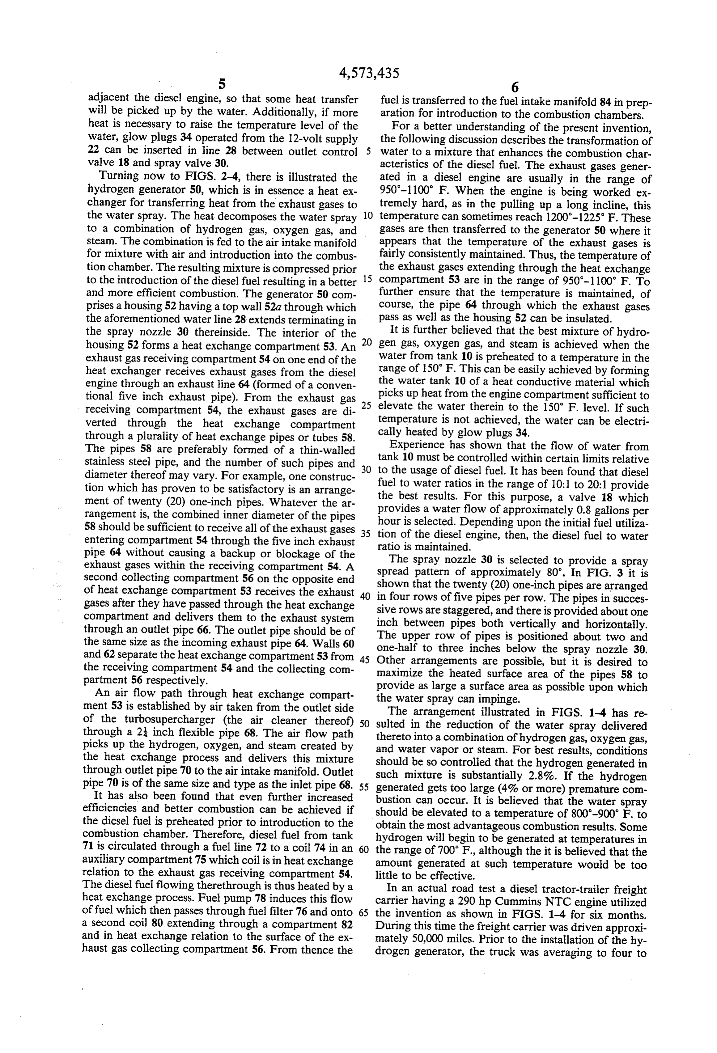
adjacent the diesel engine, so that some heat transfer fuel is transferred to the fuel intake manifold 84 in prep will be picked up by the water. Additionally, if more aration for introduction to the combustion chambers. heat is necessary to raise the temperature level of the For a better understanding of the present invention, water, glow plugs 34 operated from the 12-volt supply the following discussion describes the transformation of 22 can be inserted in line 28 between outlet control water to a mixture that enhances the combustion char valve 18 and spray valve 30. acteristics of the diesel fuel. The exhaust gases gener Turning now to FIGS. 2-4, there is illustrated the ated in a diesel engine are usually in the range of hydrogen generator 50, which is in essence a heat ex 950-1100" F. When the engine is being worked ex changer for transferring heat from the exhaust gases to tremely hard, as in the pulling up a long incline, this the water spray. The heat decomposes the water spray 10 temperature can sometimes reach 1200-1225' F. These to a combination of hydrogen gas, oxygen gas, and gases are then transferred to the generator 50 where it steam. The combination is fed to the air intake manifold appears that the temperature of the exhaust gases is for mixture with air and introduction into the combus fairly consistently maintained. Thus, the temperature of tion chamber. The resulting mixture is compressed prior the exhaust gases extending through the heat exchange to the introduction of the diesel fuel resulting in a better 15 compartment 53 are in the range of 950-1100 F. To and more efficient combustion. The generator 50 com further ensure that the temperature is maintained, of prises a housing 52 having a top wall 52a through which course, the pipe 64 through which the exhaust gases the aforementioned water line 28 extends terminating in pass as well as the housing 52 can be insulated. the spray nozzle 30 thereinside. The interior of the 20 It is further believed that the best mixture of hydro housing 52 forms a heat exchange compartment 53. An gen gas, oxygen gas, and steam is achieved when the exhaust gas receiving compartment 54 on one end of the water from tank 10 is preheated to a temperature in the heat exchanger receives exhaust gases from the diesel range of 150 F. This can be easily achieved by forming engine through an exhaust line 64 (formed of a conven the water tank 10 of a heat conductive material which tional five inch exhaust pipe). From the exhaust gas picks up heat from the engine compartment sufficient to receiving compartment 54, the exhaust gases are di 25 elevate the water therein to the 150 F. level. If such verted through the heat exchange compartment temperature is not achieved, the water can be electri through a plurality of heat exchange pipes or tubes 58. cally heated by glow plugs 34.
The pipes 58 are preferably formed of a thin-walled tank Experience has shown that the flow of water from stainless steel pipe, and the number of such pipes and 30 to the10usage must be controlled within certain limits relative of diesel fuel. It has been found that diesel diameter thereof may vary. For example, one construc tion which has proven to be satisfactory is an arrange fuel to water ratios in the range of 10:1 to 20:1 provide ment of twenty (20) one-inch pipes. Whatever the ar the best results. For this purpose, a valve 18 which provides a water flow of approximately 0.8 gallons per rangement is, the combined inner diameter of the pipes hour is selected.
58 should be sufficient to receive all of the exhaust gases 35 tion of the dieselDepending upon the initial fuel utiliza entering compartment 54 through the five inch exhaust ratio is maintained.engine, then, the diesel fuel to water pipe 64 without causing a backup or blockage of the The spray nozzle 30 is selected to provide a spray exhaust gases within the receiving compartment 54. A spread pattern of approximately 80'. In FIG. 3 it is second collecting compartment 56 on the opposite end shown that the twenty (20) one-inch pipes are arranged of heat exchange compartment 53 receives the exhaust in gases after they have passed through the heat exchange sive rows areof four rows five pipes per row. The pipes in succes compartment and delivers them to the exhaust system inch betweenstaggered, pipes and there is provided about one both vertically and horizontally.
through an outlet pipe 66. The outlet pipe should be of the same size as the incoming exhaust pipe 64. Walls 60 The upper row of pipes is positioned about two and and 62 separate the heat exchange compartment 53 from 45 one-halfarrangements to three inches below the spray nozzle 30.
the receiving compartment 54 and the collecting com Other are possible, but it is desired to maximize the heated surface area of the pipes 58 to partment 56 respectively. provide as large a surface area as possible upon which An air flow path through heat exchange compart the water spray can impinge.
ment 53 is established by air taken from the outlet side of the turbosupercharger (the air cleaner thereof) 50 sulted inarrangement
through a 2 inch flexible pipe 68. The air flow path thereto into a combinationofofthe the reduction water spray delivered hydrogen gas, oxygen gas, picks up the hydrogen, oxygen, and steam created by and water vapor or steam. For the heat exchange process and delivers this mixture should be so controlled that the best results, conditions hydrogen generated in through outlet pipe 70 to the air intake manifold. Outlet such mixture is substantially 2.8%. If the hydrogen pipe 70 is of the same size and type as the inlet pipe 68. 55 generated gets too large (4% or more) premature com It has also been found that even further increased bustion can occur. It is believed that the water spray efficiencies and better combustion can be achieved if should be elevated to a temperature of 800-900 F. to the diesel fuel is preheated prior to introduction to the obtain the most advantageous combustion results. Some combustion chamber. Therefore, diesel fuel from tank hydrogen will begin to be generated at temperatures in 71 is circulated through a fuel line 72 to a coil 74 in an the range of 700 F., although the it is believed that the auxiliary compartment 75 which coil is in heat exchange amount generated at such temperature would be too relation to the exhaust gas receiving compartment 54. little to be effective.
The diesel fuel flowing therethrough is thus heated by a In an actual road test a diesel tractor-trailer freight heat exchange process. Fuel pump 78 induces this flow carrier having a 290 hp Cummins NTC engine utilized of fuel which then passes through fuel filter 76 and onto 65 the invention as shown in FIGS. 1-4 for six months. a second coil 80 extending through a compartment 82 During this time the freight carrier was driven approxi and in heat exchange relation to the surface of the ex mately 50,000 miles. Prior to the installation of the hy haust gas collecting compartment 56. From thence the drogen generator, the truck was averaging to four to
Page 7
four and one-half miles per gallon. Subsequent to the 7. The method according to claim 1 wherein said installation and during the test, between seven and water is preheated prior to the introduction to said heat seven and one-half miles per gallon were realized. The exchanger.
motor was torn down and checked for any possible 8. Apparatus for generating and delivering a mixture damage or defect due to the use of the invention, how of hydrogen gas, oxygen gas, and steam for mixture ever, none were found. During the test, no visible pollu with diesel fuel in the combustion chamber of a diesel tion from the exhaust stack was noted under any road engine comprising:
conditions, even while changing gears, once the engine (a) a pressurized source of water; was warmed up. Thus, the heated air with a higher O (b) a heat exchanger having means associated there hydrogen and oxygen content provides better combus with for receiving water from said water source tion, burns off more of the pollutants before emission, and exhaust gases from said diesel engine in non and improves fuel efficiency. contacting, heat exchange relation to each other; While a preferred embodiment of the present inven (c) means for controlling the flow of water to said tion has been described in detail hereinabove, it is appar 15 heat exchanger responsive to the delivery rate of diesel fuel to the combustion chamber of said diesel ent that various changes and modifications might be engine;
made without departing from the scope of the invention (d) said heat exchanger comprising: set forth in the claims below.
What is claimed is: (i) an exhaust gas receiving manifold for receiving 1. Method for improving the fuel economy and emis 20 said exhaust gases from the combustion cham sion quality of a diesel engine comprising the steps of: bers of said diesel engine and a heat exchange compartment separated therefrom by a wall;
(a) delivering water from a pressurized water source (ii) a bank of heat exchange tubes formed of a heat to the water inlet of a heat exchanger at a con conducting material extending through said heat trolled rate determined responsive to the delivery exchange compartment, said tubes being ar of diesel fuel to said diesel engine; 25 ranged in a bank including a plurality of rows (b) collecting the hot exhaust gases from said diesel and columns with spaces therebetween; engine and delivering them to the exhaust gas inlet (iii) a spray nozzle mounted on the top wall of said of said heat exchanger; heat exchange compartment above said bank of (c) separating said exhaust gases into a plurality of heat exchange tubes and connected to said pres tubes or pipes extending through said heat ex 30 surized source of water;
changer and having heat conducting walls; (e) means connecting the interior of said heat ex (d) spraying water through said water inlet onto the change compartment with said combustion cham surface of the heat conducting walls at such a rate ber for circulating air through said heat exchange as to reform the atomized water droplets into hy compartment and on to said combustion chamber drogen gas, oxygen gas, and water vapor; 35 whereby hydrogen gas, oxygen gas, and steam are (e) the ratio of water delivered to the heat exchanger delivered thereto.
relative to diesel fuel delivered to the combustion 9. The apparatus according to claim 8 wherein the chamber of said diesel engine being substantially in means for controlling the flow of water to said heat the range of 1:10 to 1:20; exchanger comprises a control valve in the bottom of (f) delivering said hydrogen gas, oxygen gas, and 40 said water tank mechanically connected to and oper water vapor to the air intake of said diesel engine ated by a solenoid, a limit switch associated with the where it is mixed with air, introduced into the accelerator of said diesel engine and activated thereby combustion chamber, and compressed prior to the to transmit an electrical signal to said solenoid for the introduction of said diesel fuel for combustion. operation of said control valve.
2. The method according to claim 1 wherein the 45 10. The apparatus according to claim 8 and further process is controlled to such an extent that the amount including a fuel line extending between the diesel fuel of hydrogen gas in said mixture of said hydrogen gas, tank for said diesel engine and the fuel intake manifold oxygen gas, and water vapor is in the range of substan thereof exchanger and a means for transferring heat from said heat to said fuel line.
tially 2.8% to 3.0%. 50 11. The apparatus according to claim 8 wherein said 3. The method according to claim 2 wherein the control valve is of such size and so constructed as to temperature of said water spray is elevated to the range deliver substantially 0.8 gallons per hour and said spray
valve is so constructed 4. The method according to claim 1 wherein said angle of divergence of 80. as to generate a spray having an diesel fuel is preheated by passing it in heat exchange 55 12. The apparatus according to claim 8 wherein said relation to said heat exchanger prior to delivery to the diesel engine includes an air intake manifold and said fuel manifold of said diesel engine. heat exchange compartment is connected to said air 5. The method according to claim 1 wherein said intake manifold of said diesel engine by a flexible con mixture of hydrogen gas, oxygen gas, and water vapor duit through which said mixture of hydrogen gas, oxy is delivered from said heat exchanger to the air intake 60 gen gas, and steam are delivered thereto; said diesel manifold by establishing an air flow path from the outlet engine further including a turbosupercharger and said side of the engine turbosupercharger to the heat ex heat exchange compartment being further connected to changer where the hydrogen, oxygen, and water vapor the outlet side of said turbosupercharger for receiving a mixture is picked up and delivered back to the air intake flow of air thereinto, which air picks up said mixture of manifold. 65 hydrogen gas, oxygen gas, and steam and delivers it to 6. The method according to claim 1 wherein said said air intake manifold, water is filtered prior to introduction to said heat ex 13. The apparatus according to claim 8 and further changer. including an exhaust conduit connecting the exhaust
Page 8
manifold of said diesel engine to an exhaust gas receiv ing compartment of said heat exchanger. comprising means for filtering said water from said 14. The apparatus according to claim 8 and further water source prior to delivery to said heat exchange including means for preheating said water prior to de compartment.
livery of said heat exchange compartment. 5 15. The apparatus according to claim 8 and further
Provenance
- Collection
- Cited prior art
- Original PDF
- patentimages.storage.googleapis.com →
- Filed
- 1985-06-28
- Pages
- 8
- Method
- pdftotext (the PDF's own text layer) + pdftoppm 300dpi page scans
- Source
- Google Patents bibliographic record
- Granted
- 1986-03-04
- Inventors
- Glenn F. Shelton
- Transcribed from
- patentimages.storage.googleapis.com →