patent · US4131095
Internal combustion engine operated on a reformed gas
26 December 1978
Page 1 — bibliographic record
United States Patent (19) 11) 4,131,095 Ouchi 45) Dec. 26, 1978 54 INTERNAL COMBUSTION ENGINE 3,779,013 12/1973 Faber et al. ..................... 123/19 A OPERATED ON A REFORMED GAS 3,805,752 4/1974 123/59 EC 3,958,540 5/1976 ... 123/59 EC 75 Inventor: Keido Ouchi, Ayase, Japan 4,041,910 8/1977 ... 123/19 A 73 Assignee: Nissan Motor Company, Ltd., Japan FOREIGN PATENT DOCUMENTS (21) Appl. No.: 778,425 2623677 9/1976 Fed. Rep. of Germany. 22 Filed: Mar. 17, 1977 Primary Examiner-Charles J. Myhre 30 Foreign Application Priority Data Assistant Examiner-Jeffrey L. Yates Mar. 19, 1976 JP Japan .................................. 51-30579 57 ABSTRACT 51) Int. Cl’............................................. FO2M 25/06 When a lower engine power output is required, one of 52 U.S.C. ................................... 123/59 EC 123/3; the combustion chambers acts as a reformer operable to 123/119 A; 123/119 LR; 123/75 C; 123/90.18 convert a mixture of an ordinary fuel and air into a 58) Field of Search ........... 123/59 EC, 3, 1 A, 90.18, reformed gas which is introduced into the other com 123/119A, 119 LR, 75 C; 261/44 C bustion chambers for the power generating combustion
thereof. On the contrary, when a higher engine power output is required, all the combustion chambers are
2,113,602 4/1938 Pratt ...... 123/59 EC metric air-fuel mixture.
3,776,207 12/1973. Simko ........ ... 123/19 A 10 Clains, 5 Drawing Figures
ACCELERATOR
Page 2
Drawing sheet — no readable text.
Page 3
Drawing sheet — no readable text.
Page 4
Drawing sheet — no readable text.
Page 5
ing a second product produced in the first combustion
NTERNAL COMBUSTON ENGINE OPERATED chamber into the exhaust manifold when actuated; and ON A REFORMED GAs control means for initiating the actuations of the first mixture supply means and the first exhaust means and
The present invention relates in general to an internal also discontinuing the actuations of the second and third combustion engine system and more particularly to an mixture supply means and the second exhaust means internal combustion engine system of a kind which can when a lower engine power output is required, and for be operated on a reformed gas produced through chem initiating the actuations of the second and third mixture ical reformation of an ordinary fuel typified by gasoline. supply means and the second exhaust means and also It is well known in the art that one of the best ways to O discontinuing the actuations of the first mixture supply solve the problem of the atmospheric pollution by ex means and the first exhaust means when a high engine haust gases of internal combustion engines is to operate output power is required.
the engines with a gaseous fuel or reformed gas which Other objects and advantages of the present invention contains as combustible components, hydrogen (H2) will become more apparent from the following detailed and/or carbon monoxide (CO) and is obtained through, 15 description when taken in conjunction with the accom for example partial oxidation of, or water gas reaction panying drawings, in which:
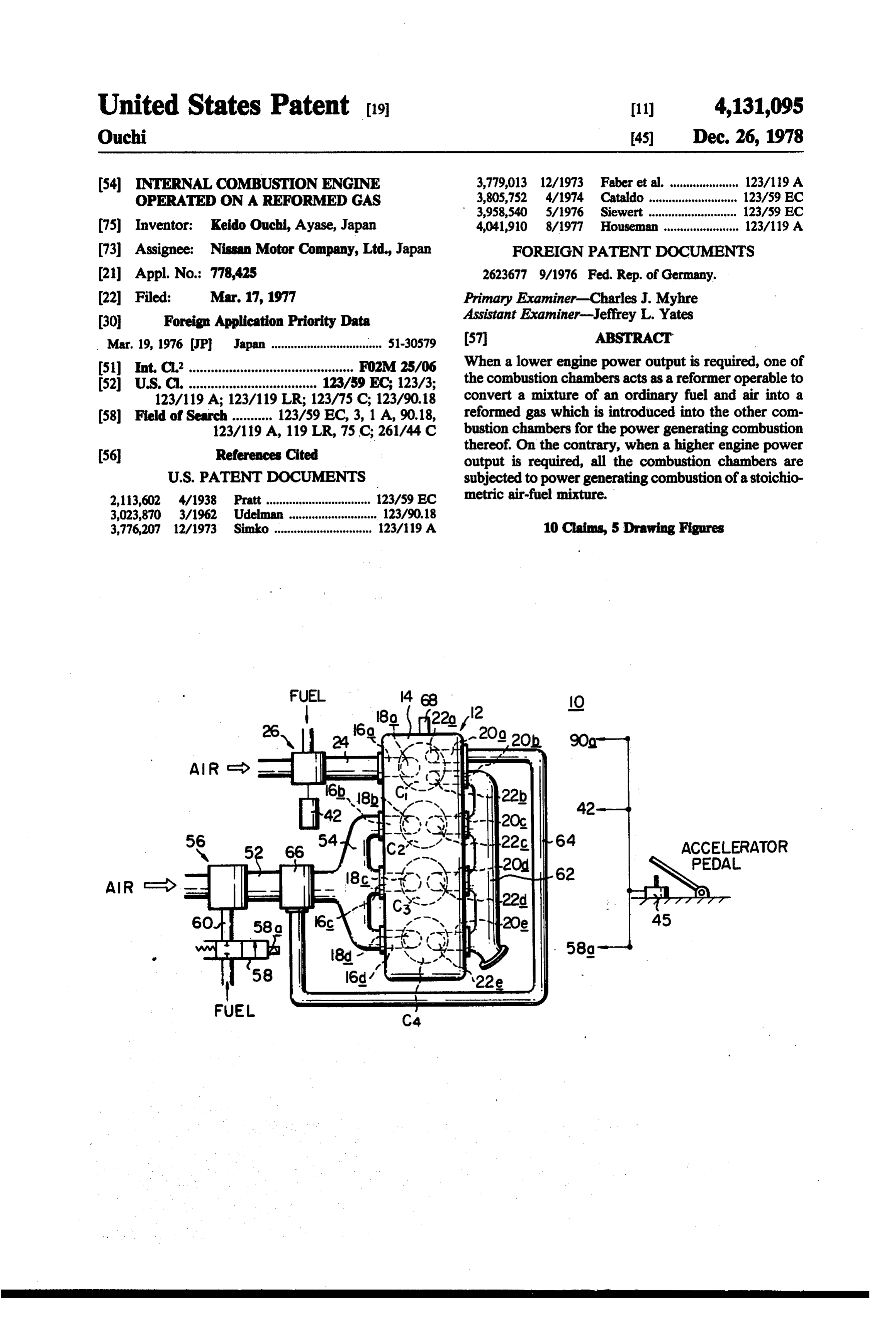
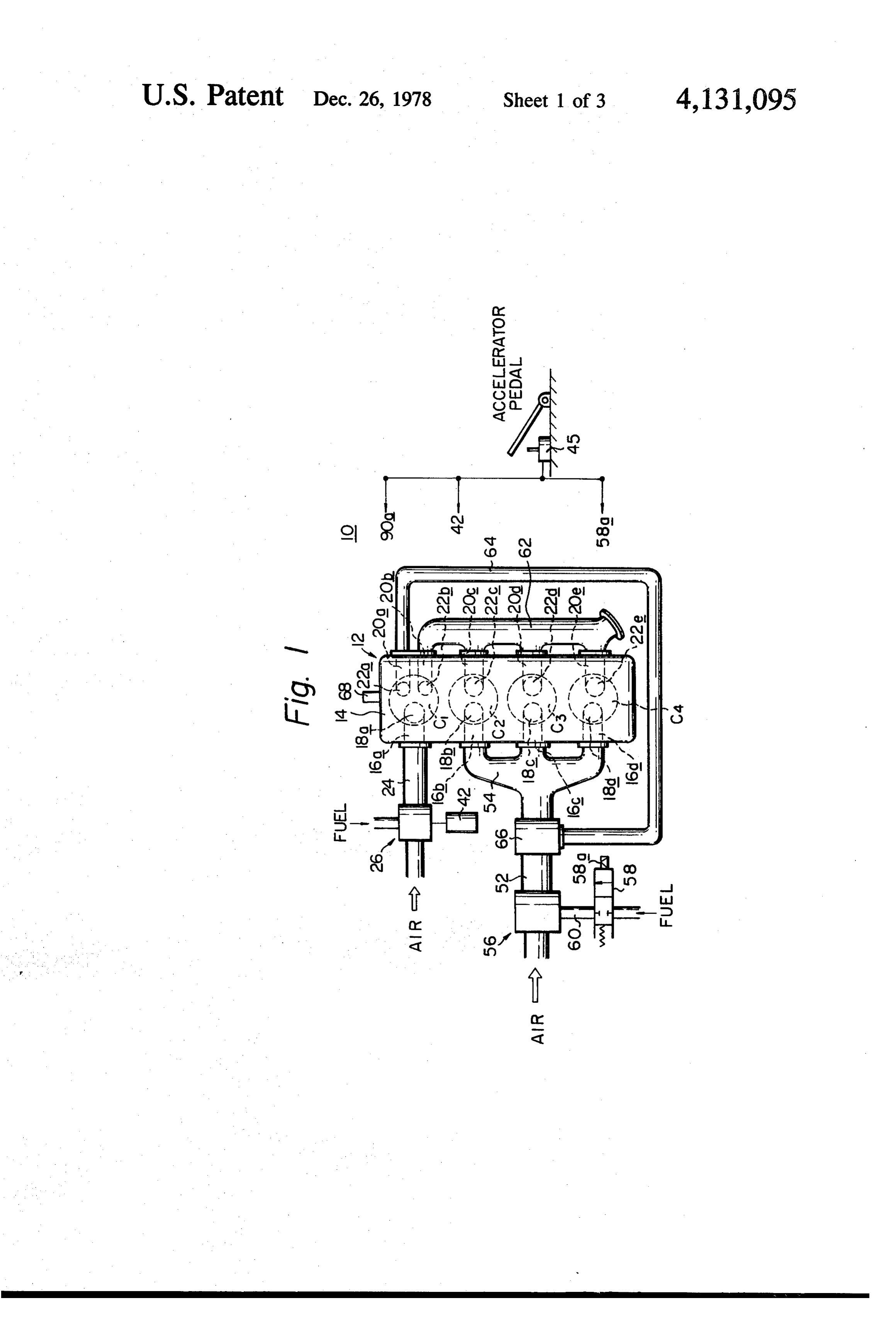
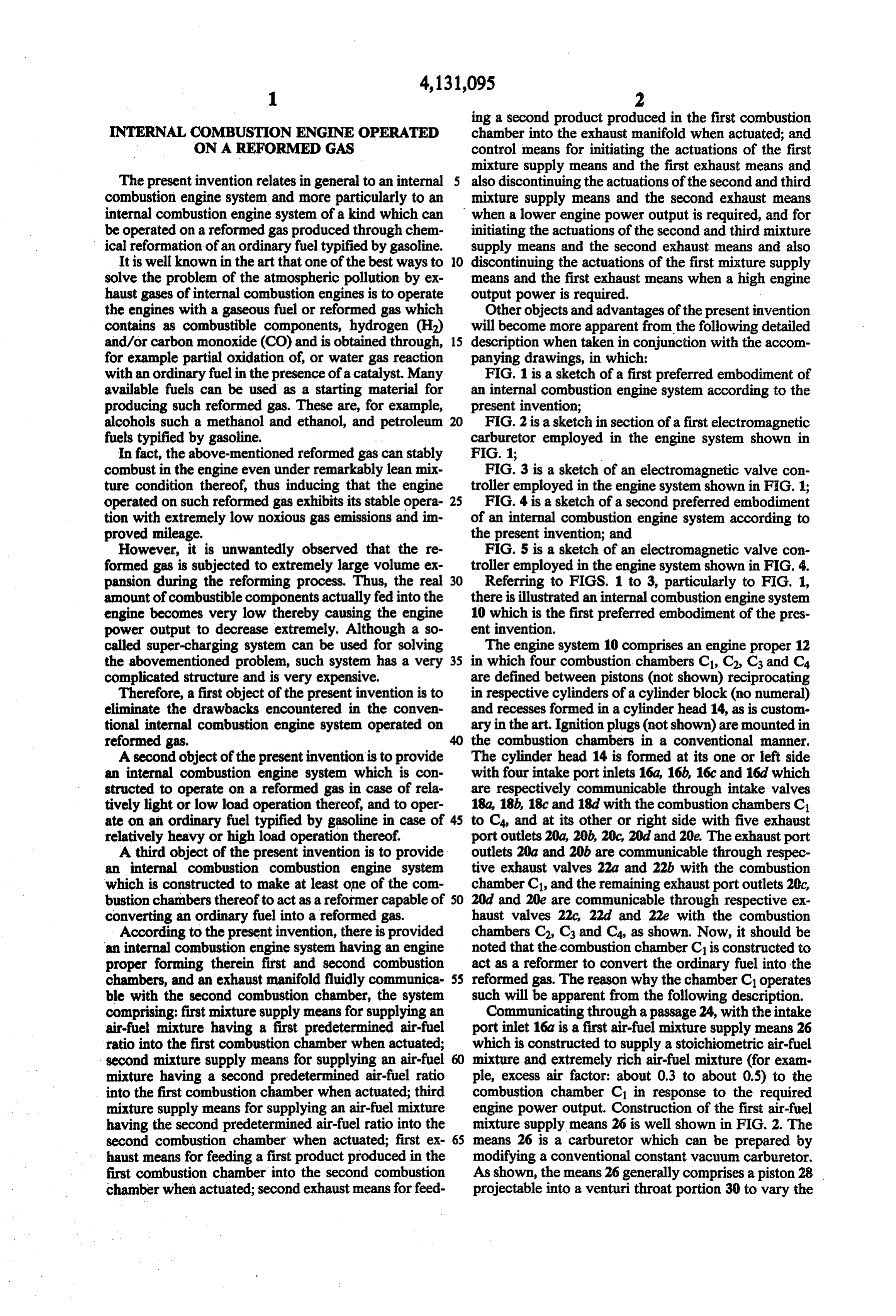
with an ordinary fuel in the presence of a catalyst. Many FIG. 1 is a sketch of a first preferred embodiment of available fuels can be used as a starting material for an internal combustion engine system according to the producing such reformed gas. These are, for example, present invention;
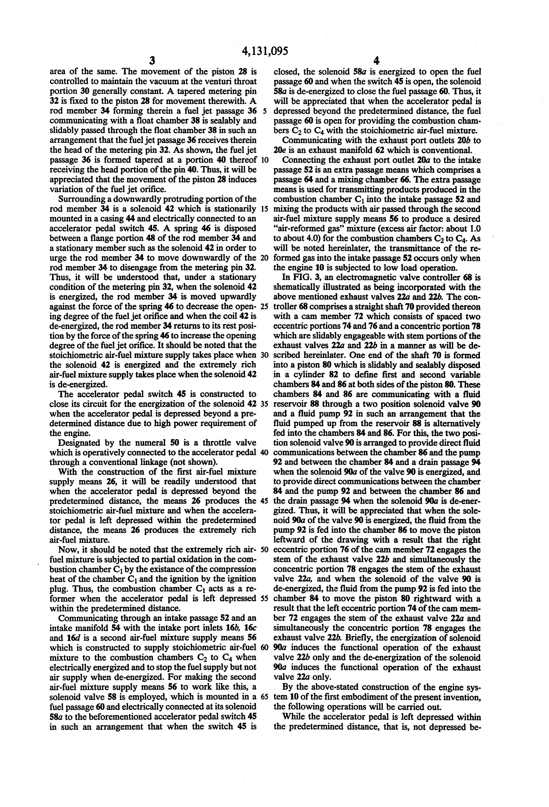
alcohols such a methanol and ethanol, and petroleum 20 FIG. 2 is a sketch in section of a first electromagnetic fuels typified by gasoline. carburetor employed in the engine system shown in In fact, the above-mentioned reformed gas can stably FIG. 1;
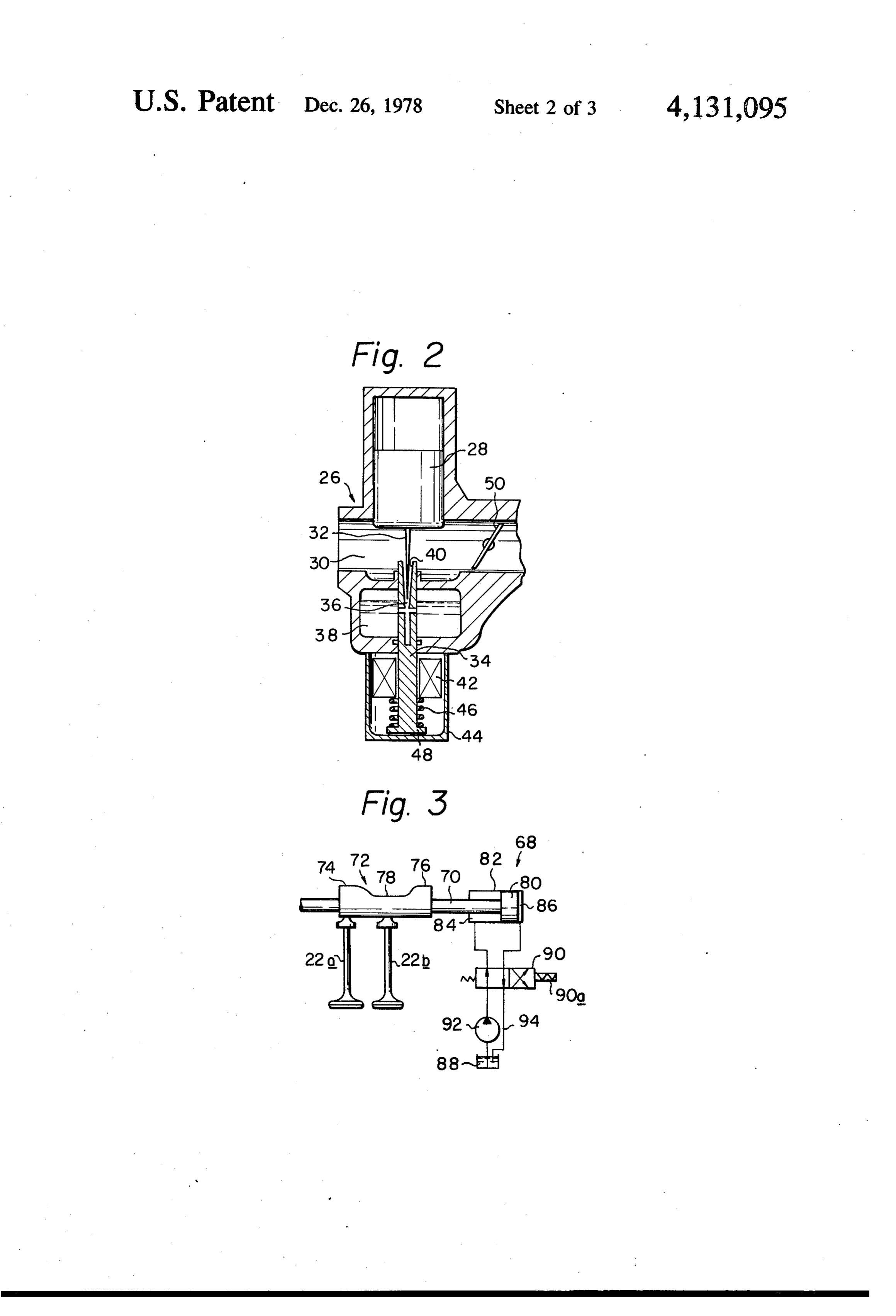
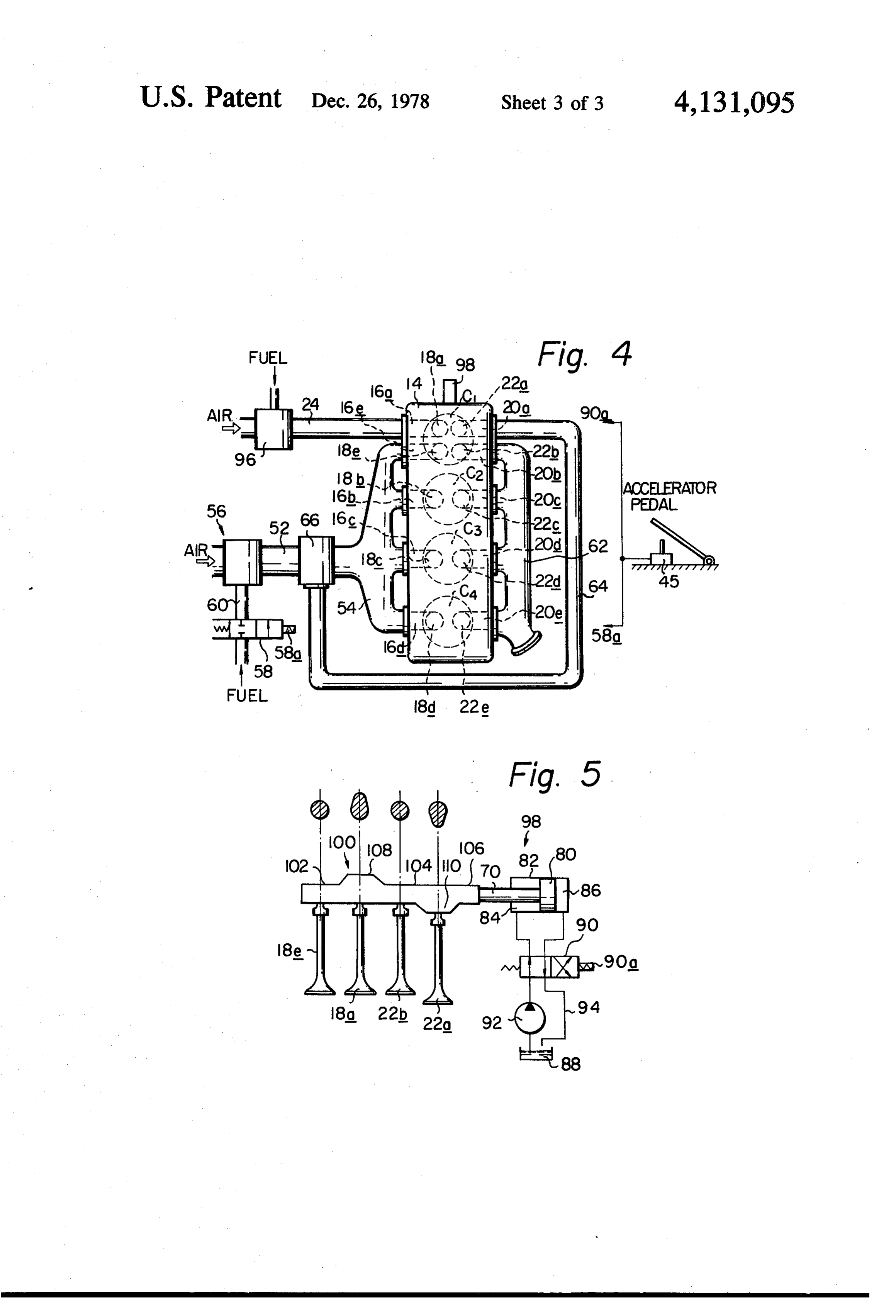
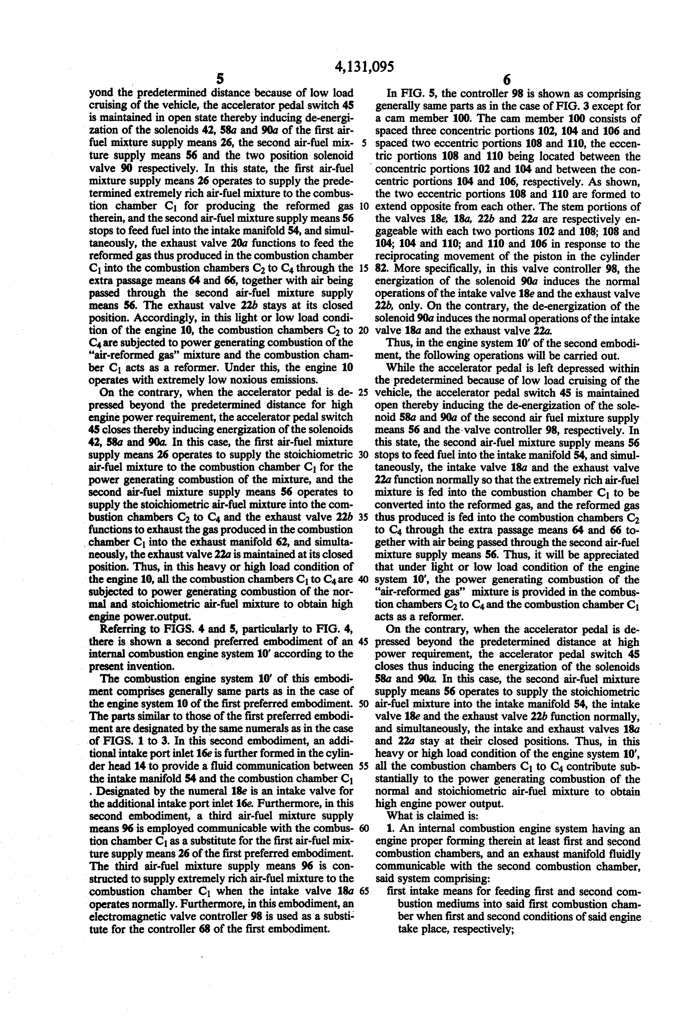
combust in the engine even under remarkably lean mix FIG. 3 is a sketch of an electromagnetic valve con ture condition thereof, thus inducing that the engine troller employed in the engine system shown in FIG. 1; operated on such reformed gas exhibits its stable opera 25 FIG. 4 is a sketch of a second preferred embodiment tion with extremely low noxious gas emissions and im of an internal combustion engine system according to proved mileage. the present invention; and However, it is unwantedly observed that the re FIG. 5 is a sketch of an electromagnetic valve con formed gas is subjected to extremely large volume ex troller employed in the engine system shown in FIG, 4. pansion during the reforming process. Thus, the real 30 Referring to FIGS. 1 to 3, particularly to FIG. 1, amount of combustible components actually fed into the there is illustrated an internal combustion engine system engine becomes very low thereby causing the engine 10 which is the first preferred embodiment of the pres power output to decrease extremely. Although a so ent invention.
called super-charging system can be used for solving The engine system 10 comprises an engine proper 12 the abovementioned problem, such system has a very 35 in which four combustion chambers C1, C2, C3 and C4 complicated structure and is very expensive. are defined between pistons (not shown) reciprocating Therefore, a first object of the present invention is to in respective cylinders of a cylinderblock (no numeral) eliminate the drawbacks encountered in the conven and recesses formed in a cylinder head 14, as is custom tional internal combustion engine system operated on ary in the art. Ignition plugs (not shown) are mounted in reformed gas. 40 the combustion chambers in a conventional manner. A second object of the present invention is to provide The cylinder head 14 is formed at its one or left side an internal combustion engine system which is con with four intake port inlets 16a, 16b, 16c and 16d. which structed to operate on a reformed gas in case of rela are respectively communicable through intake valves tively light or low load operation thereof, and to oper 18a, 18b, 18c and 18d with the combustion chambers C1 ate on an ordinary fuel typified by gasoline in case of 45 to C4, and at its other or right side with five exhaust relatively heavy or high load operation thereof. port outlets 20a, 20b, 20c, 20d and 20e. The exhaust port A third object of the present invention is to provide outlets 20a and 20b are communicable through respec an internal combustion combustion engine system tive exhaust valves 22a and 22b with the combustion which is constructed to make at least one of the com chamber C1, and the remaining exhaust port outlets 20c, bustion chambers thereof to act as a reformer capable of 50 20d and 20e are communicable through respective ex converting an ordinary fuel into a reformed gas. haust valves 22c, 22d and 22e with the combustion According to the present invention, there is provided chambers C2, C3 and C4, as shown. Now, it should be an internal combustion engine system having an engine noted that the combustion chamber C1 is constructed to proper forming therein first and second combustion act as a reformer to convert the ordinary fuel into the chambers, and an exhaust manifold fluidly communica 55 reformed gas. The reason why the chamber C1 operates ble with the second combustion chamber, the system such will be apparent from the following description. comprising: first mixture supply means for supplying an Communicating through a passage 24, with the intake air-fuel mixture having a first predetermined air-fuel port inlet 16a is a first air-fuel mixture supply means 26 ratio into the first combustion chamber when actuated; which is constructed to supply a stoichiometric air-fuel second mixture supply means for supplying an air-fuel mixture and extremely rich air-fuel mixture (for exam mixture having a second predetermined air-fuel ratio ple, excess air factor: about 0.3 to about 0.5) to the into the first combustion chamber when actuated; third combustion chamber C1 in response to the required mixture supply means for supplying an air-fuel mixture engine power output. Construction of the first air-fuel having the second predetermined air-fuel ratio into the mixture supply means 26 is well shown in FIG. 2. The second combustion chamber when actuated; first ex 65 means 26 is a carburetor which can be prepared by haust means for feeding a first product produced in the modifying a conventional constant vacuum carburetor. first combustion chamber into the second combustion As shown, the means 26 generally comprises a piston 28 chamber when actuated; second exhaust means for feed projectable into a venturi throat portion 30 to vary the
Page 6
area of the same. The movement of the piston 28 is closed, the solenoid 58a is energized to open the fuel controlled to maintain the vacuum at the venturi throat passage 60 and when the switch 45 is open, the solenoid portion 30 generally constant. A tapered metering pin 58a is de-energized to close the fuel passage 60. Thus, it 32 is fixed to the piston 28 for movement therewith. A will be appreciated that when the accelerator pedal is rod member 34 forming therein a fuel jet passage 36 5 depressed beyond the predetermined distance, the fuel communicating with a float chamber 38 is sealably and passage 60 is open for providing the combustion cham slidably passed through the float chamber 38 in such an bers C2 to C4 with the stoichiometric air-fuel mixture. arrangement that the fueljet passage 36 receives therein Communicating with the exhaust port outlets 20b to the head of the metering pin 32. As shown, the fuel jet 20e is an exhaust manifold 62 which is conventional. passage 36 is formed tapered at a portion 40 thereof 10 Connecting the exhaust port outlet 20a to the intake receiving the head portion of the pin 40. Thus, it will be passage 52 is an extra passage means which comprises a appreciated that the movement of the piston 28 induces passage 64 and a mixing chamber 66. The extra passage variation of the fuel jet orifice. means is used for transmitting products produced in the Surrounding a downwardly protruding portion of the combustion chamber C1 into the intake passage 52 and rod member 34 is a solenoid 42 which is stationarily 15 mixing the products with air passed through the second mounted in a casing 44 and electrically connected to an air-fuel mixture supply means 56 to produce a desired accelerator pedal switch 45. A spring 46 is disposed "air-reformed gas' mixture (excess air factor: about 1.0 between a flange portion 48 of the rod member 34 and to about 4.0) for the combustion chambers C2 to C. As a stationary member such as the solenoid 42 in order to will be noted hereinlater, the transmittance of the re urge the rod member 34 to move downwardly of the formed gas into the intake passage 52 occurs only when rod member 34 to disengage from the metering pin 32. the engine 10 is subjected to low load operation. Thus, it will be understood that, under a stationary In FIG. 3, an electromagnetic valve controller 68 is condition of the metering pin 32, when the solenoid 42 shematically illustrated as being incorporated with the is energized, the rod member 34 is moved upwardly above mentioned exhaust valves 22a and 22b. The con against the force of the spring 46 to decrease the open 25 troller 68 comprises a straightshaft 70 provided thereon ing degree of the fuel jet orifice and when the coil 42 is with a cam member 72 which consists of spaced two de-energized, the rod member 34 returns to its rest posi eccentric portions 74 and 76 and a concentric portion 78 tion by the force of the spring 46 to increase the opening which are slidably engageable with stem portions of the degree of the fuel jet orifice. It should be noted that the exhaust valves 22a and 22b in a manner as will be de stoichiometric air-fuel mixture supply takes place when 30 scribed hereinlater. One end of the shaft 70 is formed the solenoid 42 is energized and the extremely rich into a piston 80 which is slidably and sealably disposed air-fuel mixture supply takes place when the solenoid 42 in a cylinder 82 to define first and second variable is de-energized. chambers 84 and 86 at both sides of the piston 80. These The accelerator pedal switch 45 is constructed to chambers 84 and 86 are communicating with a fluid close its circuit for the energization of the solenoid 4235 reservoir 88 through a two position solenoid valve 90 when the accelerator pedal is depressed beyond a pre and a fluid pump 92 in such an arrangement that the determined distance due to high power requirement of fluid pumped up from the reservoir 88 is alternatively the engine. fed into the chambers 84 and 86. For this, the two posi Designated by the numeral 50 is a throttle valve tion solenoid valve 90 is arranged to provide direct fluid which is operatively connected to the accelerator pedal communications between the chamber 86 and the pump through a conventional linkage (not shown). 92 and between the chamber 84 and a drain passage 94 With the construction of the first air-fuel mixture when the solenoid 90a of the valve 90 is energized, and supply means 26, it will be readily understood that to provide direct communications between the chamber when the accelerator pedal is depressed beyond the 84 and the pump 92 and between the chamber 86 and predetermined distance, the means 26 produces the 45 the drain passage 94 when the solenoid 90a is de-ener stoichiometric air-fuel mixture and when the accelera gized. Thus, it will be appreciated that when the sole tor pedal is left depressed within the predetermined noid 90a of the valve 90 is energized, the fluid from the distance, the means 26 produces the extremely rich pump 92 is fed into the chamber 86 to move the piston air-fuel mixture. leftward of the drawing with a result that the right Now, it should be noted that the extremely rich air 50 eccentric portion 76 of the cam member 72 engages the fuel mixture is subjected to partial oxidation in the com stem of the exhaust valve 22b and simultaneously the bustion chamber C1 by the existance of the compression concentric portion 78 engages the stem of the exhaust heat of the chamber C1 and the ignition by the ignition valve 22a, and when the solenoid of the valve 90 is plug. Thus, the combustion chamber C1 acts as a re de-energized, the fluid from the pump 92 is fed into the former when the accelerator pedal is left depressed 55 chamber 84 to move the piston 80 rightward with a within the predetermined distance. result that the left eccentric portion 74 of the cam mem Communicating through an intake passage 52 and an ber 72 engages the stem of the exhaust valve 22a and intake manifold 54 with the intake port inlets 16b, 16c simultaneously the concentric portion 78 engages the and 16d. is a second air-fuel mixture supply means 56 exhaust valve 22b. Briefly, the energization of solenoid which is constructed to supply stoichiometric air-fuel 60 90a induces the functional operation of the exhaust mixture to the combustion chambers C2 to C4 when valve 22b only and the de-energization of the solenoid electrically energized and to stop the fuel supply but not 90a induces the functional operation of the exhaust air supply when de-energized. For making the second valve 22a only.
air-fuel mixture supply means 56 to work like this, a By the above-stated construction of the engine sys solenoid valve 58 is employed, which is mounted in a 65 tem 10 of the first embodiment of the present invention, fuel passage 60 and electrically connected at its solenoid the following operations will be carried out. 58a to the beforementioned accelerator pedal switch 45 While the accelerator pedal is left depressed within in such an arrangement that when the switch 45 is the predetermined distance, that is, not depressed be
Page 7
yond the predetermined distance because of low load In FIG. 5, the controller 98 is shown as comprising cruising of the vehicle, the accelerator pedal switch 45 generally same parts as in the case of FIG. 3 except for is maintained in open state thereby inducing de-energi a cam member 100. The cam member 100 consists of zation of the solenoids 42, 58a and 90a of the first air spaced three concentric portions 102, 104 and 106 and fuel mixture supply means 26, the second air-fuel mix- 5 spaced two eccentric portions 108 and 110, the eccen ture supply means 56 and the two position solenoid tric portions 108 and 110 being located between the valve 90 respectively. In this state, the first air-fuel concentric portions 102 and 104 and between the con mixture supply means 26 operates to supply the prede centric portions 104 and 106, respectively. As shown, termined extremely rich air-fuel mixture to the combus the two eccentric portions 108 and 110 are formed to tion chamber C1 for producing the reformed gas 10 extend opposite from each other. The stem portions of therein, and the second air-fuel mixture supply means 56 the valves 18e, 18a, 22b and 22a are respectively en stops to feed fuel into the intake manifold 54, and simul gageable with each two portions 102 and 108; 108 and taneously, the exhaust valve 20a functions to feed the 104; 104 and 110; and 110 and 106 in response to the reformed gas thus produced in the combustion chamber reciprocating movement of the piston in the cylinder Clinto the combustion chambers C2 to C4 through the 15 82. More specifically, in this valve controller 98, the extra passage means 64 and 66, together with air being energization of the solenoid 90a induces the normal passed through the second air-fuel mixture supply operations of the intake valve 18e and the exhaust valve means 56. The exhaust valve 22b stays at its closed 22b, only. On the contrary, the de-energization of the position. Accordingly, in this light or low load condi solenoid 90a induces the normal operations of the intake tion of the engine 10, the combustion chambers C2 to 20 valve 18a and the exhaust valve 22a. Care subjected to power generating combustion of the Thus, in the engine system 10' of the second embodi "air-reformed gas' mixture and the combustion cham ment, the following operations will be carried out. ber C1 acts as a reformer. Under this, the engine 10 While the accelerator pedal is left depressed within operates with extremely low noxious emissions. the predetermined because of low load cruising of the On the contrary, when the accelerator pedal is de 25 vehicle, the accelerator pedal switch 45 is maintained pressed beyond the predetermined distance for high open thereby inducing the de-energization of the sole engine power requirement, the accelerator pedal switch noid 58a and 90a of the second air fuel mixture supply 45 closes thereby inducing energization of the solenoids means 56 and the valve controller 98, respectively. In 42, 58a and 90a. In this case, the first air-fuel mixture this state, the second air-fuel mixture supply means 56 supply means 26 operates to supply the stoichiometric 30 stops to feed fuel into the intake manifold 54, and simul air-fuel mixture to the combustion chamber C1 for the taneously, the intake valve 18a and the exhaust valve power generating combustion of the mixture, and the 22a function normally so that the extremely rich air-fuel second air-fuel mixture supply means 56 operates to mixture is fed into the combustion chamber C1 to be supply the stoichiometric air-fuel mixture into the com converted into the reformed gas, and the reformed gas bustion chambers C2 to C4 and the exhaust valve 22b 35 thus produced is fed into the combustion chambers C2 functions to exhaust the gas produced in the combustion to C4 through the extra passage means 64 and 66 to chamber C into the exhaust manifold 62, and simulta gether with air being passed through the second air-fuel neously, the exhaust valve 22a is maintained at its closed mixture supply means 56. Thus, it will be appreciated position. Thus, in this heavy or high load condition of that under light or low load condition of the engine the engine 10, all the combustion chambers C1 to C4 are 40 system 10, the power generating combustion of the subjected to power generating combustion of the nor "air-reformed gas' mixture is provided in the combus mal and stoichiometric air-fuel mixture to obtain high tion chambers C2 to C4 and the combustion chamber C1 engine power.output. acts as a reformer.
Referring to FIGS. 4 and 5, particularly to FIG. 4, On the contrary, when the accelerator pedal is de there is shown a second preferred embodiment of an 45 pressed beyond the predetermined distance at high internal combustion engine system 10' according to the power requirement, the accelerator pedal switch 45 present invention. closes thus inducing the energization of the solenoids The combustion engine system 10' of this embodi 58a and 90a, In this case, the second air-fuel mixture ment comprises generally same parts as in the case of supply means 56 operates to supply the stoichiometric the engine system 10 of the first preferred embodiment. 50 air-fuel mixture into the intake manifold 54, the intake The parts similar to those of the first preferred embodi valve 18e and the exhaust valve 22b function normally, ment are designated by the same numerals as in the case and simultaneously, the intake and exhaust valves 18a of FIGS. 1 to 3. In this second embodiment, an addi and 22a stay at their closed positions. Thus, in this tional intake portinlet 16e is further formed in the cylin heavy or high load condition of the engine system 10", der head 14 to provide a fluid communication between 55 all the combustion chambers C1 to C4 contribute sub the intake manifold 54 and the combustion chamber C1 stantially to the power generating combustion of the . Designated by the numeral 18e is an intake valve for normal and stoichiometric air-fuel mixture to obtain the additional intake port inlet 16e. Furthermore, in this high engine power output.
second embodiment, a third air-fuel mixture supply What is claimed is:
means 96 is employed communicable with the combus 1. An internal combustion engine system having an tion chamber C1 as a substitute for the first air-fuel mix engine proper forming therein at least first and second ture supply means 26 of the first preferred embodiment. combustion chambers, and an exhaust manifold fluidly The third air-fuel mixture supply means 96 is con communicable with the second combustion chamber, structed to supply extremely rich air-fuel mixture to the said system comprising:
combustion chamber C1 when the intake valve 18a first intake means for feeding first and second com operates normally. Furthermore, in this embodiment, an bustion mediums into said first combustion cham electromagnetic valve controller 98 is used as a substi ber when first and second conditions of said engine tute for the controller 68 of the first embodiment. take place, respectively;
Page 8
second intake means for feeding a third combustion inducing the electric energization of said first electro medium into said second combustion chamber magnetic carburetor, said second electromagnetic car when said second condition takes place; buretor and said electromagnetic valve controller when reformed gas transmitting means for transmitting a the accelerator pedal is depressed beyond a predeter product produced in said first combustion chamber mined distance.
into said second combustion chamber when said 6. An internal combustion engine system as claimed first condition takes place; in claim 3, in which said first electromagnetic carbure exhaust means for feeding a product produced in said tor comprises a piston projectable into a venturi throat first combustion chamber into said exhaust mani portion to vary the area of the same, the movement of fold when said second condition takes place; and 10 said piston being so controlled as to maintain the vac control means for causing said first and second condi uum at said venturi throat portion generally constant; a tions when lower and higher engine power outputs tapered metering pin fixed to said piston for synchro are required, respectively. nous movement therewith; a rod member forming 2. An internal combustion engine system as claimed therein a fluid jet passage communicating with a float in claim 1, in which said reformed gas transmitting 15 chamber, said rod member being longitudinally slidably means comprises a first exhaust valve operatively con arranged so as to receive the leading portion of said nected to said first combustion chamber; a first passage metering pin into said fluid jet passage thereof; a spring way providing first fluid communication between said for biasing said rod member to move in a direction to first combustion chamber and a conduit portion of said increase the opening area defined by said fluid jet pas second intake means via said first exhaust valve; and a 20 sage and said leading portion of said metering pin; and mixing chamber disposed in said conduit portion for a solenoid for causing said rod member to move in the mixing the product coming from said first combustion opposite direction to decrease said opening area when chamber through said passage with air passed through electrically energized.
said second intake means; further in which said exhaust 7. An internal combustion engine system as claimed means comprises a second exhaust valve operatively 25 in claim 5, in which said electromagnetic valve control connected to said first combustion chamber at a position ler comprises a cam member having thereon two spaced spaced from said first exhaust valve; and a second pas eccentric portions and a concentric portion located sageway providing second fluid communication be between said eccentric portions, said cam member being tween said first combustion chamber and said exhaust rotated around its axis and axially slidable to take first manifold via said second exhaust valve; said first and 30 and second positions, said first position being a position second exhaust valves being controlled in such a man in which said first and second exhaust valve are slidably ner that when said first condition takes place, said sec engaged with one of said eccentric portions and said ond exhaust valve stays closed to shut said second pas concentric portion, respectively, said second position sage, and when said second condition takes place, said being a position in which said first and second exhaust first exhaust valve stays closed to shut said first passage. 35 valves are slidably engageable with said concentric 3. An internal combustion engine system as claimed portion and the other of said eccentric portions; a piston in claim 2, in which said first intake means is a first and cylinder unit operating to move said cam member electromagnetic carburetor which is constructed to into said first position when a fluid is fed into a first produce said second combustion medium when electri chamber defined in said unit and to move said cam cally energized and to produce said first combustion member into said second position when a fluid is fed medium when de-energized. into a second member defined in said unit; and a two 4. An internal combustion engine system as claimed position electromagnetic valve disposed between said in claim 3, in which said second intake means is a second piston and cylinder unit and a fluid reservoir in such a electromagnetic carburetor which is constructed to manner that the fluid from said fluid reservoir is fed into produce said second combustion medium when electri 45 said second chamber of said unit when electrically ener cally energized and to pass through only air when de gized and the fluid from said fluid reservoir is fed into energized. said first chamber of said unit when de-energized. 5. An internal combustion engine system as claimed 8. An internal combustion engine system as claimed in claim 4, in which said control means comprises an in claim 1, in which the first combustion medium is electromagnetic valve controller controlling said first 50 richer than the second combustion medium. and second exhaust valves in such a manner that said 9. An internal combustion engine system as claimed first exhaust valve stays closed and simultaneously said in claim 8, in which the first combustion medium is second exhaust valve initiates the normal operation richer than the third combustion medium. thereof when electrically energized, and said first ex 10. An internal combustion engine system as claimed haust valve initiates the normal operation thereof and 55 in claim 9, in which the third combustion medium has a simultaneously said second exhaust valve stays closed substantially stoichiometric air-fuel ratio. when de-energized; and an accelerator pedal switch for
Provenance
- Collection
- Cited prior art
- Original PDF
- patentimages.storage.googleapis.com →
- Filed
- 1977-03-17
- Pages
- 8
- Method
- pdftotext (the PDF's own text layer) + pdftoppm 300dpi page scans
- Source
- Google Patents bibliographic record
- Granted
- 1978-12-26
- Inventors
- Keido Ouchi; Nissan Motor Co Ltd
- Transcribed from
- patentimages.storage.googleapis.com →