patent · US4041910
Combustion engine
16 August 1977
Page 1 — bibliographic record
United States Patent (19) 11) 4,041,910 Houseman 45) Aug. 16, 1977 54 COMBUSTION ENGINE 3,426,524 2/1969 Straub .............. . . . . . . . . 60/620 X 3,717,129 2/1973 Fox .................................... 123/3 X 75) Inventor: John Houseman, Pasadena, Calif. 3,789,807 2/1974 Pinkerton ................... 123/59 ECX 73) Assignee: The United States of America as 3: 48: Sto 1.85: represented by the Administrator of 3,524,576 12/1975 Siewert. 123/59 EC X the National Aeronautics and Space s Administration, Washington, D.C. Primary Examiner-Carroll B. Dority, Jr. Assistant Examiner-Craig R. Feinberg 21 Appl. No.: 564,622 Attorney, Agent, or Firm-Monte F. Mott; Wilfred 22 Filed: Apr. 2, 1975 Grikfa; John R. Manning 5 Int. Cl? ....................................... Fo2B 75/20 (57 ABSTRACT 52 U.S. C. ................................. 123/59 EC: 123/3; An arrangement for an internal combustion engine is 123/37; 123/119 A; 123/122 AB; 123/DIG. 8 provided in which one or more of the cylinders of the 58 Field of Search .................... 123/1 R, 37, 59 EC, engine are used for generating hydrogen rich gases 123/122 G, 122 AB, 59 PC, DIG. 8, 119 A; from hydrocarbon fuels, which gases are then mixed 60/278,279, 620 with air and injected into the remaining cylinders to be s used as fuel. When heavy load conditions are encoun 56) References Cited tered, hydrocarbon fuel may be mixed with the hydro
1,490,604 4/1924. Evelyn. 123/122 AB into the remaining cylinders as fuel.
3,030,819 4/1962 Edelbrock ...................... 23/59 PC 5 Claims, 4 Drawing Figures
ENRC MEN
CONTROL
GASONE Ca
AR Ydroea - R.C. Gao
EXHAUst
2 22 ZZZYZ t ad 5 % 2. 2 % first s1 2 2 2 2 E2
% 2
Page 2
Drawing sheet — no readable text.
Page 3
Drawing sheet — no readable text.
Page 4
Drawing sheet — no readable text.
Page 5
Drawing sheet — no readable text.
Page 6
very rapidly and provides a very violent reaction which
COMBUSTON ENGINE is extremely explosive and almost impossible to control. Furthermore, according to the patent, for mixing air
ORIGIN OF THE INVENTION with the decomposed products of hydrazine, a high The invention described herein was made in the per 5 pressure source of air is required. Since a high pressure formance of work under a NASA contract and is sub air compressor is expensive to operate, this adds to the ject to the provisions of section 305 of the National cost of the system.
Aeronautics and Space Act of 1958, Public Law 85-568 Hydrazine is classified as a corrosive liquid, and must (72STAT. 435; 42USC457). be carefully transported under a special label. Conse 10 quently the invention described in the patent is not
BACKGROUND OF THE INVENTION believed practical for automotive application as it is This invention relates to an improved method and much too dangerous to have any hydrazine on board. means for operating an internal combustion engine so that it provides, using some of its cylinders, a hydrogen OBJECT AND SUMMARY OF THE INVENTION rich gas which can then be used as a fuel by the remain 15 An object of this invention is the provision of a ing cylinders. method and means for operating an internal combustion A vast amount of research is being directed toward engine from a hydrocarbon fuel which substantially eliminating the nitric oxide (NO) emissions from inter eliminates nitrous oxide and hydrocarbon emissions. nal combustion engines and also for improving the effi Another object of this invention is the provision of a ciency of the operation of an internal combustion en 20 more efficient method for operating an internal combus gine. It has been found that when hydrogen is mixed tion engine which also substantially eliminates nitrous with a hydrocarbon fuel, a much leaner ratio of hydro oxides and hydrocarbon emissions.
carbon fuel to air can be used in the internal combustion A further object of this invention is to provide a sim engine than would otherwise be possible, in view of the plified method and means for using an internal combus fact that the hydrogen can support combustion whereas 25 tion engine for generating a hydrogen rich gas from a lean ratio of hydrocarbon fuel and air cannot support hydrocarbon fuel, which can then be used as fuel for the combustion. It has also been found that when the ratio remaining portion of the engine. of hydrocarbon fuel to air is "lean' beyond a certain Yet another object of this invention is to provide a point, then the amount of NO produced as a result of a novel and safe method and means for using an internal use of the mixture in an internal combustion engine is 30 combustion engine for generating a hydrogen rich gas substantially eliminated. Thus lean operation results in a from a hydrocarbon fuel which avoids the danger of an low flame temperature which yields low NO. explosion.
In a patent application Ser. No. 387,342, filed Aug. 10, The foregoing and other objects of the invention are 1973 by Jack Rupe entitled System for Minimizing In achieved ternal Combustion Engine Pollution Emission, there is and air andbyinjecting 35 mixing a hydrocarbon fuel such as gasoline, them into one or more cylinders of described and shown an arrangement for generating an internal combustion hydrogen and mixing the hydrogen with a hydrocarbon this application are twoengine. Exemplary throughout fuel and air and then injecting them into an internal cylinders are permitted to compressThecylinders. pistons in the combustion engine whereby the amount of NO pro and fuel. The amount of air mixed with mixture the of air the hydrocar duced by the internal combustion engine is substantially 40 bon reduced. In that application there is described and causefuel in a fuel rich carburetor is only sufficient to a partial oxidation of the fuel so that when the shown a hydrogen generator which produces the hy compressed mixture is ignited by a spark, it will not drogen for use in the internal combustion engine.
In an application for a hydrogen rich gas generator, decompose, but rather it is only partially oxidized to Ser. No. 428,444, filed Dec. 28, 1973, by this inventor, 45 provide hydrogen (H2) and carbon monoxide (CO) there is described an arrangement for a hydrogen rich principally, along with other products of the partial gas generator for generating gases required in the sys oxidation.
tem for the type which has been described. While these genThe resulting gas mixture, hereafter termed a hydro rich gas, is then mixed with air and injected into the hydrogen gas generators are effective for the intended purpose, they constitute an auxiliary piece of equip 50 remaining cylinders of the internal combustion engine ment, requiring peripherial service equipment such as a known mannerbyofthe to be ignited spark plugs and is used in the well fuel to power the engine. The amount starting system, an air pump, etc. If a source of hydro gen rich gases can be provided without such auxiliary of air mixed with the hydrogen rich gas in a "lean car equipment, there could be a savings in cost and a simpli buretor' prior to injection in the remaining cylinders is fication of the equipment, 55 the amount required for completing oxidation, whereby In a patent to Mikulasek et al., U.S. Pat. No. the hydrogen forms H2O and the carbon monoxide 2,648,317, there is shown an arrangement for using at forms CO2. Some excess of air, up to a maximum of least one piston of an internal combustion engine into 30%, is beneficial for better fuel economy and low NO. which vaporized hydrazine is injected. The piston of For all normal operation, where a great deal of power is the cylinder is allowed to compress the mixture. Then 60 not required, the output of the engine driven by the the hydrazine is detonated by an electric discharge for hydrogen rich gas is adequate. However, if more power the purpose of being decomposed into hydrogen, nitro should be desired, the lean carburetor may be fed gaso gen and ammonia. The decomposition products of the line, which is mixed with the hydrogen rich gas and air. hydrazine are then mixed with air to form a further The control required for feeding the lean carburetor explosive mixture which, when ignited, produces pres 65 liquid fuel may be a foot pedal control, and is operated sure and releases heat to be transformed into mechanical in the same manner as where a foot pedal is depressed energy. The problem with the arrangement described all the way to provide additional power in present day and shown in the patent, is that hydrazine decomposes motor cars.
Page 7
The novel features of the invention are set forth with required, the hydrogen rich gas is only mixed with air. particularity in the appended claims. The invention will This time a "lean' air fuel mixture is used. The overall best be understood from the following description when air/fuel mass ratio of the engine is in the range of 15 to read in conjunction with the accompanying drawings. 20. As previously pointed out, when emergency power is required, e.g., when passing or when getting into a
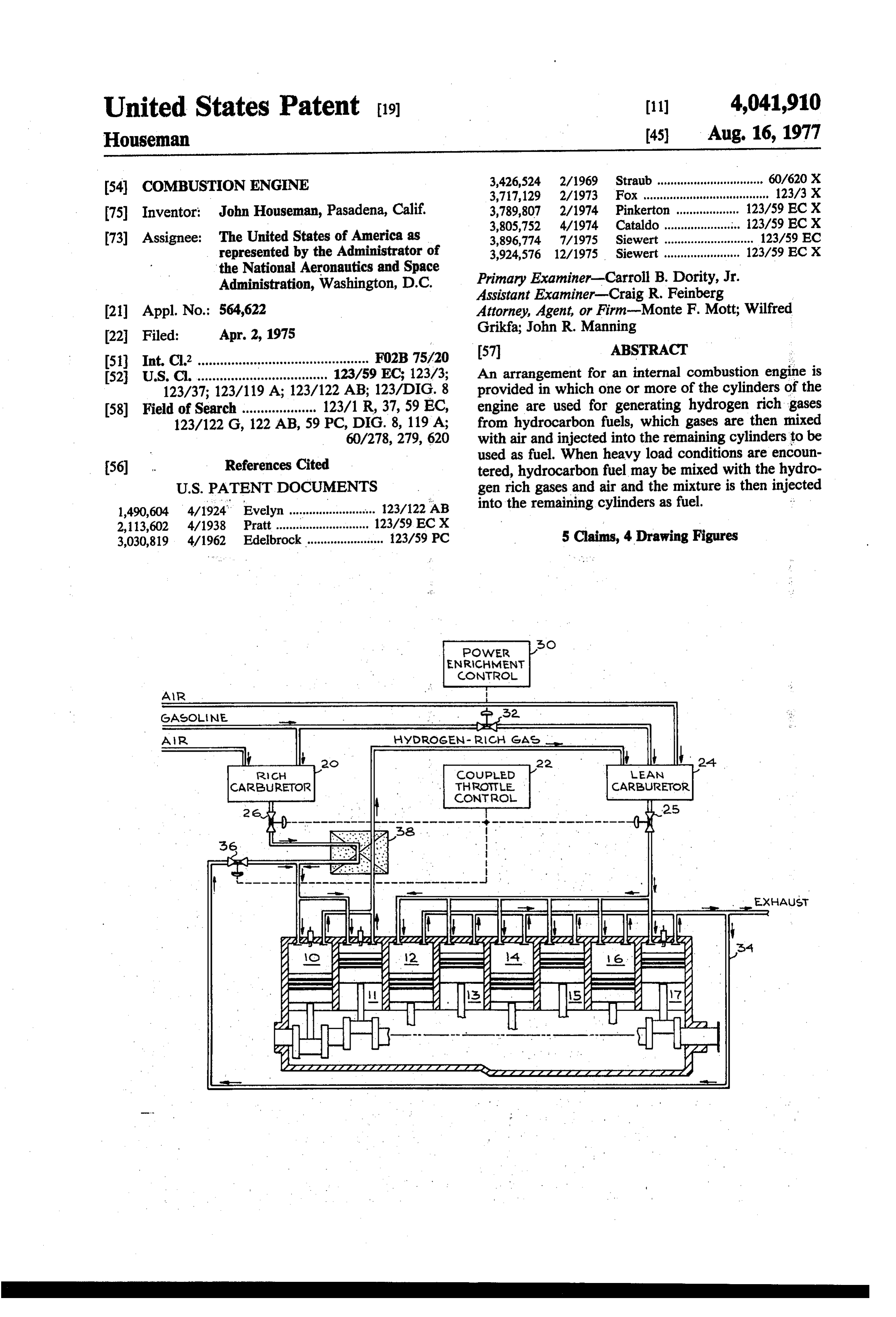
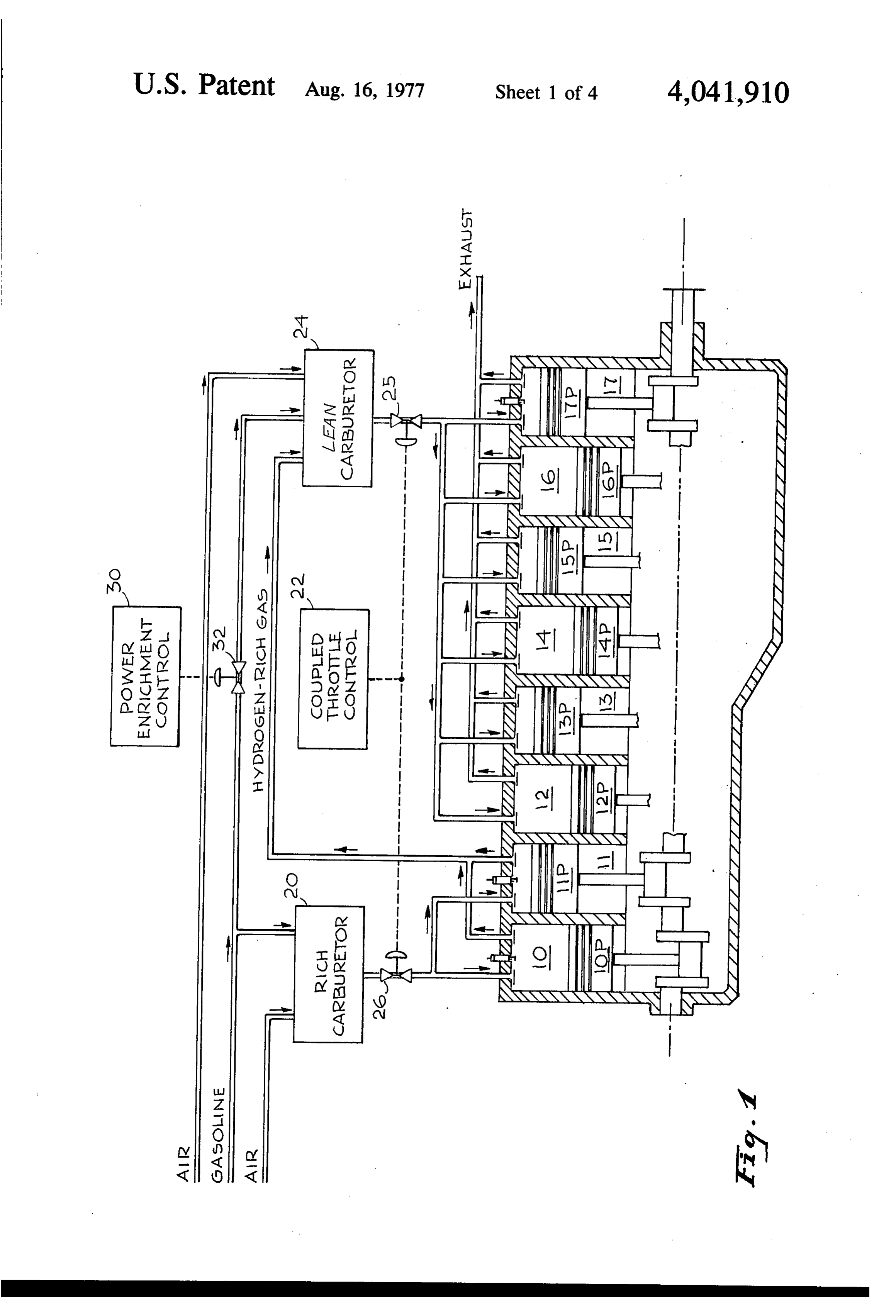
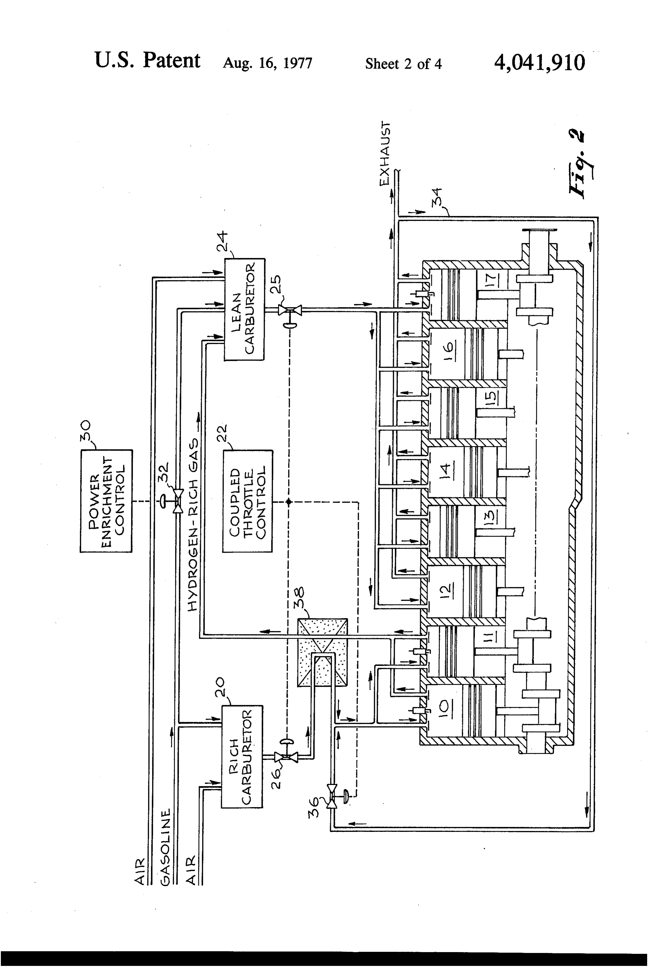
BRIEF DESCRIPTION OF THE DRAWINGS freeway, then the power enrichment control 30 is actu FIG. 1 is a schematic drawing of an arrangement of ated, whichopens valve 32 to enable gasoline to be an internal combustion engine in accordance with this supplied to the lean carburetor. There it is mixed with invention. the hydrogen rich gas and air. FIG. 2 illustrates another arrangement of an internal 10 The output of the lean carburetor 24 is then applied, combustion engine in accordance with this invention. in well known fashion, to the gas using cylinders 12 FIG. 3 is a schematic drawing showing an arrange through 17 to be ignited and to be converted into more ment of a prechamber type of engine modified in accor useful power. The exhaust products from the respective dance with this invention. pistons are removed in the normal fashion for internal FIGS. 4 and 5 are schematic drawings showing other 15 combustion engine.
arrangements of a prechamber internal combustion en Because the rich and lean carburetor throttle valves gine modified in accordance with this invention. 25 and 26 are coupled to the same control (coupled
DESCRIPTION OF THE PREFERRED
throttle control or accelerator) constant equivalent ratios in both rich and lean cylinders is assured, essen
EMBODIMENTS 20 tially independently of load and rpm (except for power In tests using the Federal test gasoline, "Indolene', it enrichment with gasoline which increases the equiva has been found that at an air/fuel ratio of 14.65, all of lence ratio in the lean cylinders.) It will be obvious that the fuel is converted to CO2 and H2O. As the air/fuel the lean and rich carburetor throttle valve 25 and 26, as ratio is reduced, H, and CO start to form. In theory, well as the valve 32 can be set to adjust the amount of soot (C) should not start to form until an air/fuel ratio 25 the mixtures which are passing therethrough. This is of 5:5 is reached. Soot suppression can be obtained by well known in the use of a hydrogen rich gas, instead of adding water, however, it is desirable to use an air/fuel gasoline as a fuel poses no new problems in the art. It ratio in which a substantial amount of H2 and CO are should be noted that the 8 cylinders of the schematically produced without producing soot and without adding illustrated engine are all connected to the same crank water. This is what is accomplished by the present in 30 shaft (not shown) and it is not intended that there be any vention. changes in the arrangement of the spark plugs, spark Referring now to FIG. 1, a schematic drawing of an ignition control, fuel distribution, injection and/or ex internal combustion engine, by way of example, an 8 haust, of a standard internal combustion engine, other cylinder engine, is shown, which is modified in accor than what is shown in the drawings. Essentially the dance with this invention. The 8 cylinders respectively 35 modifications shown comprise the use of the rich and 10 through 17, each has a piston therein, respectively lean carburetors with a coupled throttle control, power 10P through 17P. By way of example, and not to serve enrichment control and the fuel feed arrangements as a limitation upon the invention, two of the cylinders wherein hydrogen generation occurs in one or more are assigned the function of generating hydrogen rich cylinders. The exhaust from these cylinders are con gas as well as part of propulsion power, and the remain nected to the lean carburetor, which then feeds the ing 6 cylinders provide the rest of the propulsion for the other cylinders either with or without additional gaso engine. A carburetor 20, designated as a "rich carbure line.
tor', is used to mix hydrocarbon fuel and air for the gas In order to maximize the hydrogen rich gas produc generating cylinders. It demand feeds the mixture to the tion, the air/fuel ratio used to produce the hydrogen cylinders 10, 11 under control of a "coupled throttle 45 rich gas should be as low as possible. This is normally control' 22, which also controls the mixture fed from a limited by the onset of soot formation. The exact air/flean carburetor 24 into the gas using cylinders 12 uel ratio at which soot formation starts varies considera through 17. bly from engine to engine and depends on the degree of The coupled throttle control 22, which can be the atomization and the uniformity of mixing of the fuel and well known foot pedal, for example, exercises control 50 the air.
over the mixture fed to cylinders 10, 11 by controlling It has been found that by either vaporizing the fuel a valve 26. This determines, the amount of the "rich' and mixing it with preheated air, prior to induction into gasoline-air mixture admitted into the gas generating the hydrogen rich gas generating cylinders or by the cylinders. An air fuel mass ratio in the range of 7 introduction of some of the exhaust from the propulsion through 11 is preferred. The coupled throttle control 55 cylinders which contain water, into the hydrogen rich also demand controls a valve 25 to determine the gas generating cylinders, or by the actual addition of amount of mixture fed to the remaining cylinders of the steam or water, soot formation can be prevented, thus engine. allowing air/fuel ratios down to as low as 6.5. The pistons 10P and 11P enable intake of the rich FIG. 2 shows schematically, an arrangement of an mixture on a downstroke, and then compress it. Upon 60 internal combustion engine which recirculates the ex the completion of the compression stroke, the mixture is haust from the propulsion cylinders and preheats the ignited by a spark plug (not shown) in the usual fashion, vaporized air/hydrocarbon fuel mixture to improve the generating heat which causes a rapid expansion of the hydrogen rich gas output. Similar functioning structure gases, driving the pistons downwardly to generate as is shown in FIG. 1 will receive the same reference power to also form H and CO among other gases. The 65 numerals.
hydrogen rich gases are evacuated on the next compres A portion of the exhaust of cylinders 12 through 17 is sion stroke of the cylinders and are fed to the lean car returned over a line 34 and through a control valve 36, buretor 24. There, except when a surge of power is to be mixed with the incoming air/hydrocarbon mix
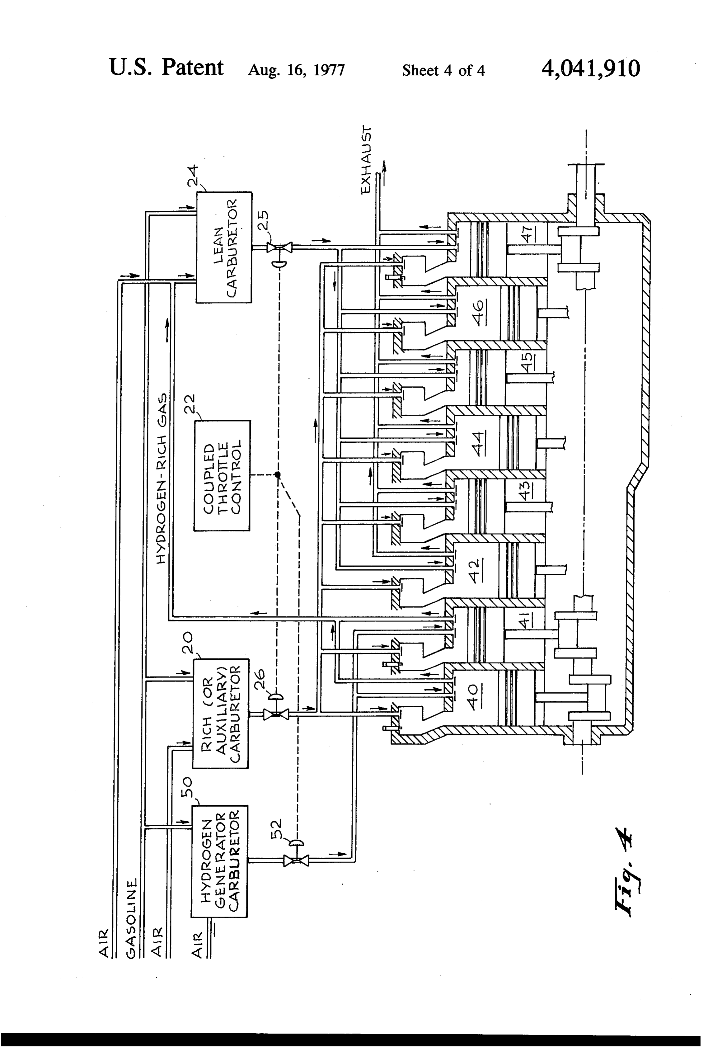
Page 8
ture, which is being injected into the hydrogen rich gas hydrogen rich gas together with the remaining three generating cylinders. The valve 36 is under the control prechambers. However, the engine is shown here as an of the coupled throttle control 22. The line extending 8 cylinder engine, since making an 8 cylinder engine is from the control 26 of the rich carburetor down to the normally the case in the United States. The only change hydrogen rich gas generating cylinders passes through a that has to be made to this type of engine, in accordance heat exchanger 38. The heat exchanger absorbs the heat with this invention, is to plug the main cylinder inlet from the hot hydrogen rich gases, which are the output valve for the cylinders which are used for hydrogen of the cylinders 10 and 11, and transfers this heat to the rich gas generation and to modify the exhaust manifold line extending from the control valve 26 which is deliv from these cylinders so that the hydrogen rich combus tion products from these two cylinders is taken to the ering the rich mixture of hydrogen fuel and air to the 10 lean hydrogen gas generating cylinders thereby preheating carburetor air inlet line. The lean carburetor can the rich mixture and vaporizing the fuel. then be adjusted to operate in the ultra lean region of Hydrogen enrichment produces the best fuel econ air/fuel ratios of 20 to 30. It should be noted that the omy with an engine that is a so-called lean burning lean carburetor as well as the rich carburetor is being engine. This means that gasoline can be burned at high 15 fed gasoline at all time. However, the amount of gaso air/fuel ratios. The leanest engine currently available line fed to the lean carburetor is much less than would commercially is a pre-chamber stratified charged en otherwise be used, in view of its being mixed with hy gine made by the Honda Motor Company. Several drogen rich gas. This is evidenced by the fact that the other companies have similarengines under active de air/fuel ratio is raised between 20 and 30. velopment. It operates up to air/fuel ratio of 22 at high 20 In order to overcome a possible problem of the hy speeds, and over a ratio of 16 to 20 at lower speeds. In drogen gas generating cylinders receiving an insuffi accordance with this invention, this engine can be con cient charge at high rpm, the main chamber inlet valves verted to provide internal hydrogen generation to en of the hydrogen gas generating cylinders 40 and 41 may able it to be operated using an ultra lean region of air/f. be connected to receive a charge from the rich carbure uel ratios of up to 30. 25 tor directly as well as the charge coming through the FIG. 3 is a schematic arrangement of a prechamber associated prechambers. However, to insure that the stratified charge engine which has been modified, in main chambers of the hydrogen rich gas generating accordance with this invention, to internally generate a cylinders receive the optimum mixture, an arrangement, hydrogen rich gas which is subsequently burned as the such as is shown in FIG. 4, may be employed. Here, a fuel of the engine, 30 special carburetor designated as a hydrogen generator With each chamber or cylinder 40 through 47 of the carburetor 50 is shown, with its own control valve 52, stratified charged engine, there is an associated pre also controlled by the coupled throttle control 22. chamber 40A through 47A. Each cylinder has a piston Should soot suppression prove to be a problem the therein respectfully 41P through 47P. As before, there techniques previously described and shown in connec is a coupled throttle control 22 which operates the con 35 tion with FIG.2 may be used, namely lean exhaust gas trol valves 25 and 26 to control the amount of fuel being recirculation as well as preheating of the incoming rich supplied from the respective rich carburetor and lean fuel mixture to the hydrogen gas generating cylinders. carburetor. The rich carburetor normally delivers a rich This invention overcomes one of the disadvantages of mixture to the prechambers 40A through 47A while the previous systems wherein an independent hydrogen lean carburetor normally delivers a lean mixture to the rich gas generator separately generates hydrogen gas main chambers 42 through 47. Each prechamber has its from a hydrocarbon fuel. There about 20% of the en own inlet valve for the rich charge as well as a spark ergy in the fuel is lost in making a hydrogen rich gas. In plug. Each main chamber has its own inlet valve and this invention, the heat released during the production exhaust valve. A compression stroke of the piston in a of the hydrogen rich gas is converted into mechanical main chamber also compresses a mixture in the pre 45 power. Thus the 20% energy loss has been eliminated. chamber to the same degree. Upon completion of a Another way of expressing this is to say that this inven compression stroke the mixture in the prechamber is tion provides a 100% efficient generator of hydrogen ignited. rich gas compared to an 80% efficient generator de When the mixtures in each of the hydrogen generat scribed in previous systems. Tests have shown an in ing prechambers 40A and 41A, and main chambers 40 50 crease in fuel economy of the order of 10% over the and 41, are ignited a hot hydrogen rich gas is generated. conventionally operated engine. Also, power is produced during the expansion of this Another advantageous feature of this invention is the gas in the main chambers 40 and 41. On the exhaust extremely low hydrocarbon emission when running on stroke the hydrogen rich gas is fed to the lean carbure hydrogen rich gas only (i.e., without gasoline enrich tor where it is mixed with air and hydrocarbon fuel. 55 ment in the lean cylinders). The reason for this phenom Thereafter, the mixture is demand fed through control enon is that there is no hydrocarbon fuel entering the valve 25 into the respective main chambers 42 through lean cylinders, so there is no HC emission either. When 47 of the stratified charge engine. When the rich mix gasoline enrichment is used, the HC emissions are simi ture which is introduced in usual fashion into the pre lar to a conventional engine.
chambers 42A through 47A, is ignited, not only is some 60 There has accordingly been described and shown additional hydrogen rich gas generated but, because of herein a novel, and useful method and means for using its high temperature it ignites and mixes with the mix one or more cylinders of an internal combustion engine ture which was injected into an associated main cham for generating a hydrogen rich gas which is then used ber from the lean carburetor, thereby providing more by the remaining cylinders of the engine as fuel. Not power for the piston down stroke. 65 only does this arrangement minimize the presence of This prechamber engine is normally shown as a 4 NO, and hydrocarbons but it also provides for a more cylinder engine by foreign manufacturers. In that case, efficiently operated engine.
1 of the 4 cylinders may be devoted to generating a What is claimed:
Page 9
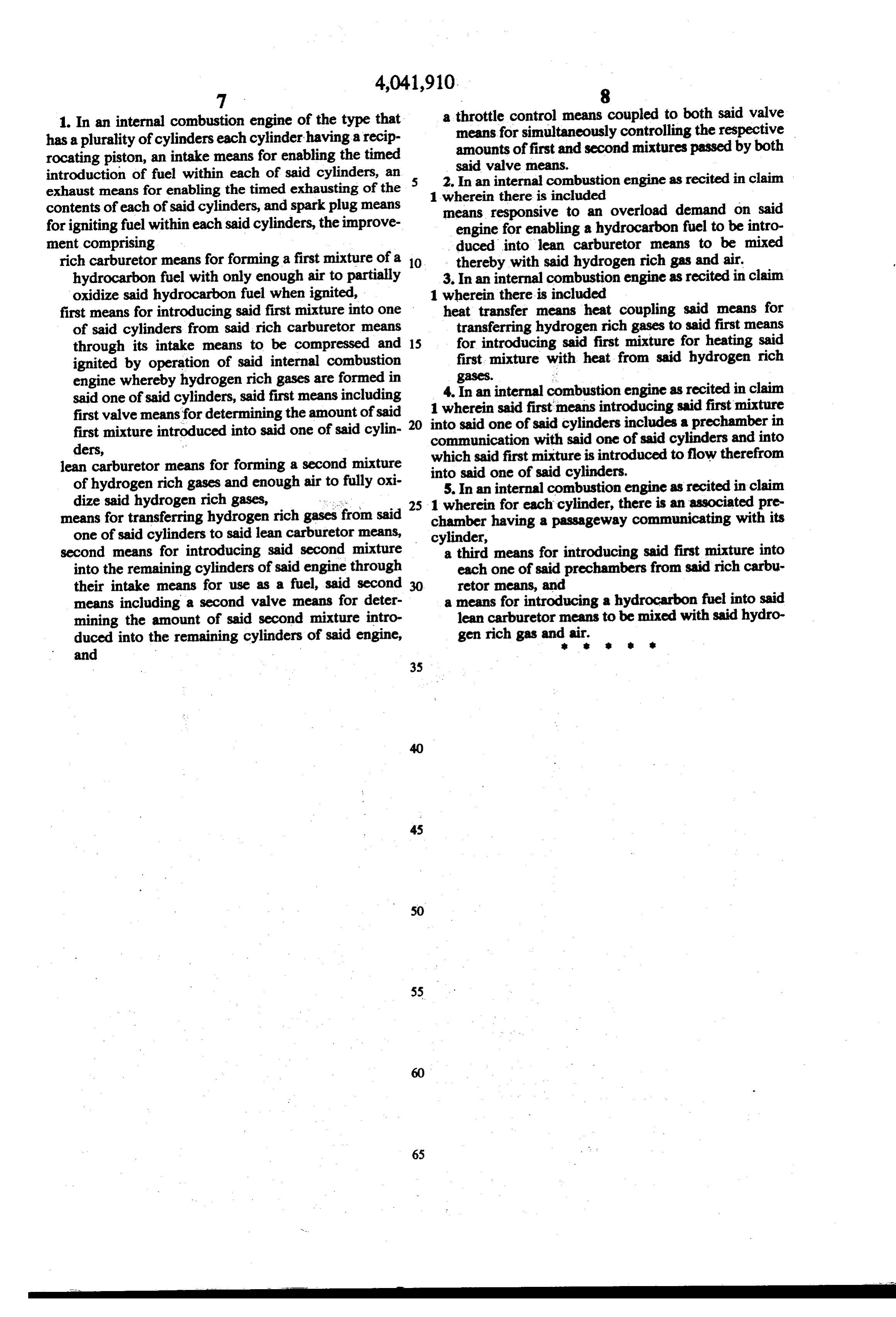
1. In an internal combustion engine of the type that a throttle control means coupled to both said valve has a plurality of cylinders each cylinder having a recip means for simultaneously controlling the respective rocating piston, an intake means for enabling the timed amounts of first and second mixtures passed by both introduction of fuel within each of said cylinders, an 5 2. said valve means.
exhaust means for enabling the timed exhausting of the 1 whereininternal
In an combustion engine as recited in claim there is included contents of each of said cylinders, and spark plug means means responsive to an overload demand on said for igniting fuel within each said cylinders, the improve engine for enabling a hydrocarbon fuel to be intro ment comprising duced into lean carburetor means to be mixed rich carburetor means for forming a first mixture of a 10 thereby with said hydrogen rich gas and air. hydrocarbon fuel with only enough air to partially 3. In an internal combustion engine as recited in claim oxidize said hydrocarbon fuel when ignited, 1 wherein there is included first means for introducing said first mixture into one heat transfer means heat coupling said means for of said cylinders from said rich carburetor means transferring hydrogen rich gases to said first means through its intake means to be compressed and 15 for introducing said first mixture for heating said ignited by operation of said internal combustion first mixture with heat from said hydrogen rich engine whereby hydrogen rich gases are formed in gases. :
said one of said cylinders, said first means including 4. In an internal combustion engine as recited in claim 1 wherein said first means introducing said first mixture first valve means for determining the amount of said 20 into said one of said cylinders includes a prechamber in first mixture introduced into said one of said cylin communication ders, with said one of said cylinders and into which said first mixture lean carburetor means for forming a second mixture into said one of said cylinders. is introduced to flow therefrom of hydrogen rich gases and enough air to fully oxi 5. In an internal combustion engine as recited in claim dize said hydrogen rich gases, - -. 25 1 wherein for each cylinder, there is an associated pre means for transferring hydrogen rich gases from said chamber having a passageway communicating with its one of said cylinders to said lean carburetor means, cylinder, second means for introducing said second mixture a third means for introducing said first mixture into into the remaining cylinders of said engine through each one of said prechambers from said rich carbu their intake means for use as a fuel, said second 30 retor means, and means including a second valve means for deter a means for introducing a hydrocarbon fuel into said mining the amount of said second mixture intro lean carburetor means to be mixed with said hydro duced into the remaining cylinders of said engine, gen rich gas and air.
and
Provenance
- Collection
- Cited prior art
- Original PDF
- patentimages.storage.googleapis.com →
- Filed
- 1975-04-02
- Pages
- 9
- Method
- pdftotext (the PDF's own text layer) + pdftoppm 300dpi page scans
- Source
- Google Patents bibliographic record
- Granted
- 1977-08-16
- Inventors
- John Houseman; National Aeronautics and Space Administration NASA
- Transcribed from
- patentimages.storage.googleapis.com →