patent · US20070065765A1
Energy converting device
22 March 2007
Page 1 — bibliographic record
(19) United States (12) Patent Application Publication (10) Pub. No.: US 2007/0065765 A1
Bierbaumer (43) Pub. Date: Mar. 22, 2007 (54) ENERGY CONVERTING DEVICE (30) Foreign Application Priority Data Oct. 14, 2003 (AT)...................................... A 1618/2003 (76) Inventor: Hans-Peter Bierbaumer, O O Rohr/Kremstal (AT) Publication Classification
Correspondence Address: (51) Int. Cl.
WILLIAM COLLARD (52) I't I? (2006.01) 431A2 COLLARD & ROE, P.C. Oa - -- - - ------------- ------------ --- ---------- --- --- ------- --- --- --------
1077 NORTHERN BOULEVARD (57) ABSTRACT
9 The invention relates to a device for converting energy comprising a gas generator (6) for generating a hydrogen (21) Appl. No.: 10/575,791 oxygen mixture or Brown gas with a reaction chamber (19) in which electrodes (29) are disposed. The reaction chamber (22) PCT Filed: Oct. 6, 2004 (19) is of a rotationally symmetrical shape with respect to an axis (18) and at least certain regions of inner boundary (86). PCT No.: PCT/ATO4/OO341 surfaces (20) of the reaction chamber (19) in the region of a jacket (21) of the reaction chamber (19) are formed by
S 371(c)(1), inner electrode surfaces (30, 31) of the electrodes (29) of the
9 / - 1
Page 2
Drawing sheet — no readable text.
Page 3
Drawing sheet — no readable text.
Page 4
Drawing sheet — no readable text.
Page 5
Drawing sheet — no readable text.
Page 6
Drawing sheet — no readable text.
Page 7
Drawing sheet — no readable text.
Page 8
US 2007/0065765 A1 Mar. 22, 2007
ENERGY CONVERTING DEVICE the gas generator, oriented coaxially with the axis of the 0001. The invention relates to a device and a method for rotation chamber, and the rotor is designed to generate a converting energy, incorporating a gas generator for gener rotation with an angular velocity in the range of 10 s' to 25 ating a hydrogen-oxygen mixture or Brown gas, of the type s', the advantage of which is that a force can be applied which is concentrated so that it acts on the bubbles of Brown having the features outlined in the introductory parts of claims 1 and 23. gas as they form in the direction towards the axis of the reaction chamber.
discloses a heating device and a method of generating heat, 0008 Another embodiment of the device for converting based on the cyclical combustion of Brown gas. Brown gas energy is provided with an outlet orifice in one of the base is produced from water in a so-called Brown gas generator plate and/or cover plate closing off the reaction chamber, using a special form of electrolysis. Due to the electrolytic which is disposed coaxially with the axis of the reaction treatment of the water in the Brown gas generator, it is chamber, the advantage of which is that Brown gas forming transformed into a special state and consists of a mixture of in the region of the axis of the reaction chamber can be easily dissociated hydrogen and oxygen atoms. As specified in drawn off through this outlet orifice. U.S. Pat. No. 6,443,725 B1, the Brown gas is delivered to a 0009. In one embodiment, the outlet orifice is formed by combustion chamber where it is converted back into water molecules after combustion. The water molecules are then a suction lance which can be displaced parallel with the ionised to produce hydrogen and oxygen by absorbing direction of the axis of the reaction chamber, the advantage infrared radiation. of which is that it minimises the degree to which the working medium is undesirably sucked out with the Brown gas which 0003) Document U.S. Pat. No. 4,014,777. A discloses has formed in the reaction chamber because the immersion devices and a method for producing hydrogen and oxygen in depth of the Suction lance can be adjusted accordingly so the form of Brown gas. This Brown gas is then used for that the outlet orifice can be fed as close as possible past the welding or Soldering. In one embodiment of a Brown gas site where the Brown gas is being generated. generator, an electrolysis cell is described as having serially connected electrode plates. These electrode plates are 0010. The advantage of the device for converting energy secured to tubes made from insulating material, and open provided with an acoustic source or in which the acoustic ings of the tubes are provided between respective adjacent Source generates Sound at a frequency in a range of 25 kHz electrodes. The electrodes are placed in electrical contact, in to 55 kHz, preferably 38.5 kHz to 41.5 kHz, even more the end region of the tubes, with an external power Supply. preferably 40.5 kHz, is that applying sound to the working The tubes incorporating the electrodes are immersed in a medium increases the rate at which the Brown gas forms. solution of water and KOH. Through the orifices in the 0011. Also of advantage are embodiments of the device tubes, solution is able to penetrate between the electrodes, in which the acoustic source is disposed coaxially with the on the one hand, and the resultant gas is able to leave the axis of the reaction chamber or at least a part-region of the space between the electrodes, on the other hand. The advan inner boundary surface of the reaction chamber is formed as tage which this device has over conventional gas welding a reflector which concentrates the Sound, because the Sound apparatus is that hydrogen and oxygen are automatically can be concentrated in the region of the axis as a result and produced in the correct ratio, enabling a neutral flame to be the acoustic pressure can be increased in the region of the generated. aX1S.
0004 The objective of the invention is to propose a 0012. Also of advantage is the embodiment of the device device and a method for converting energy using a hydro in which the gas generator is provided with an infrared gen-oxygen mixture or Brown gas, by means of which a Source, because exposing the working medium to infrared high degree of efficiency can be achieved. Another objective radiation likewise has a positive effect on the formation of of the invention is to achieve increased productivity when Brown gas and the formation of Brown gas is accelerated. generating the hydrogen-oxygen mixture or Brown gas.
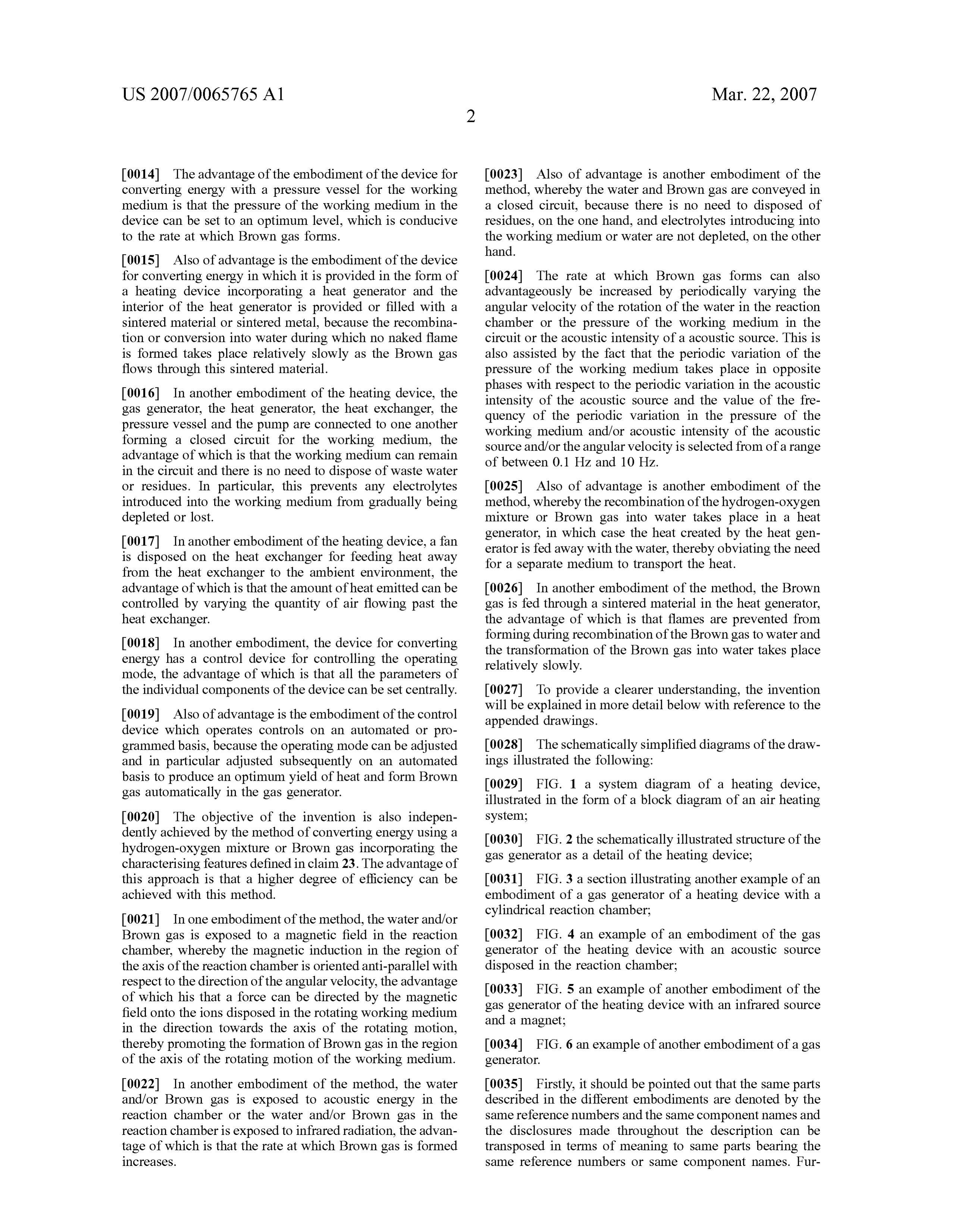
0005. This objective is achieved by the invention on the 0013 In another embodiment of the device for converting basis of the device for converting energy incorporating the energy, the gas generator is provided with a magnet and the characterising features defined in claim 1. The advantage of magnetic field direction of the magnet in the region of the this device resides in the fact that a higher degree of axis of the reaction chamber is oriented anti-parallel with efficiency can be achieved because the rotationally shaped respect to the direction of the angular velocity of the rotor or design of the reaction chamber of the gas generator permits the rotating motion of the working medium in the reaction the simultaneous intervention of an electric field and a chamber, the advantage of which is that the separation of rotating motion on the working medium or water, which is molecular oxygen and molecular hydrogen is Suppressed at conducive to the formation of Brown gas and increases the the two electrodes in favour of generating Brown gas. Due rate at which it forms as a result. to the rotating movement of the working medium in the magnetic field of the magnet with an anti-parallel position 0006 Also of advantage is another embodiment in which ing of the magnetic field direction with respect to the angular at least one inlet connector for the working medium oriented Velocity of the rotating motion of the working medium, a a tangent to the jacket of the reaction chamber is provided resultant force can effectively be applied to ions in the in the jacket of the reaction chamber, because the working working medium by the magnetic field which forces the ions medium is displaced in rotation solely due to the movement on a spiral path of motion extending in the direction towards of the working medium as it flows into the reaction chamber. the axis of the reaction chamber. This prevents the ions from 0007. In the case of other embodiments of the device for moving close to the electrodes, where they would otherwise converting energy, a rotor with a rotation axis is provided in separate.
Page 9
US 2007/0065765 A1 Mar. 22, 2007
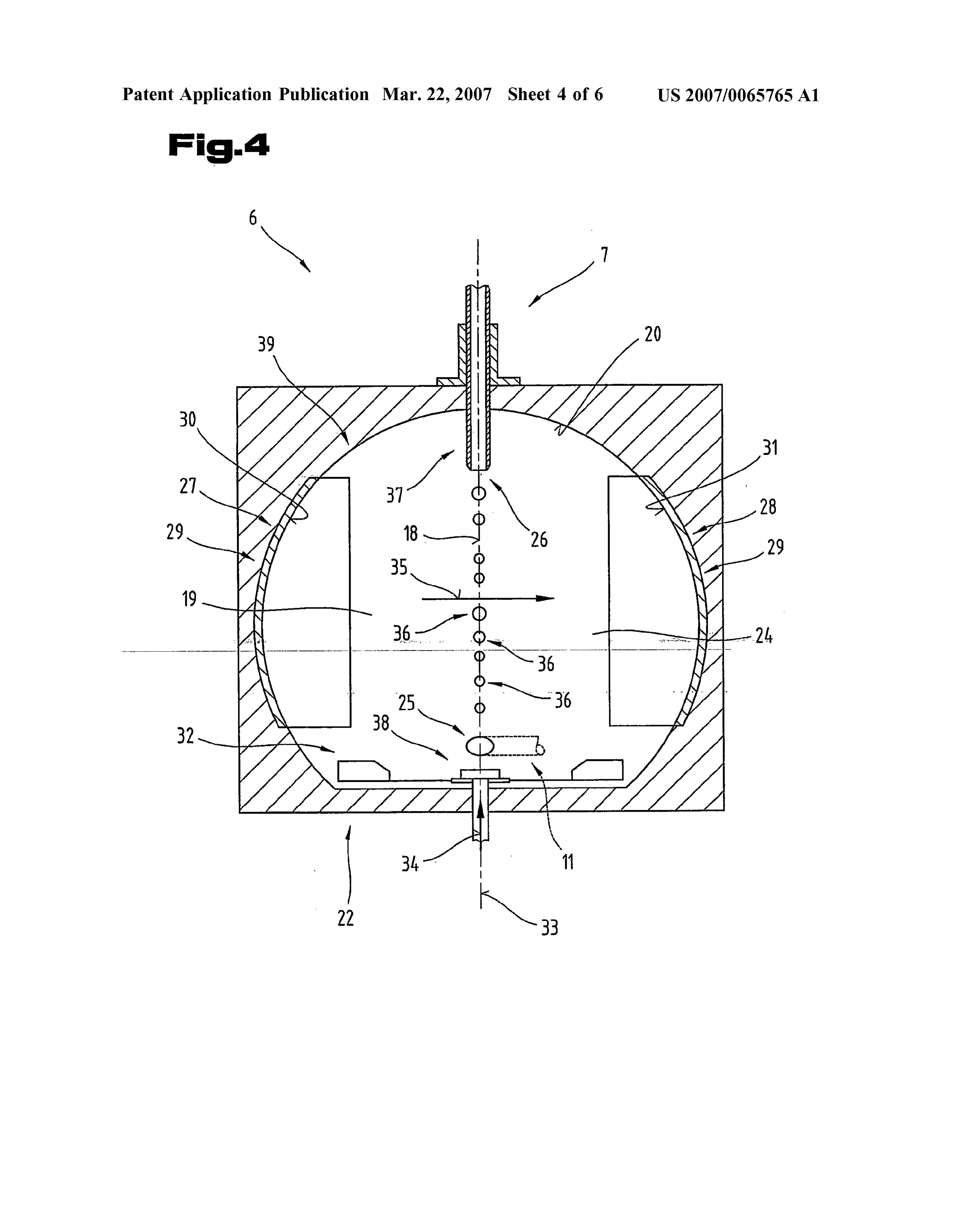
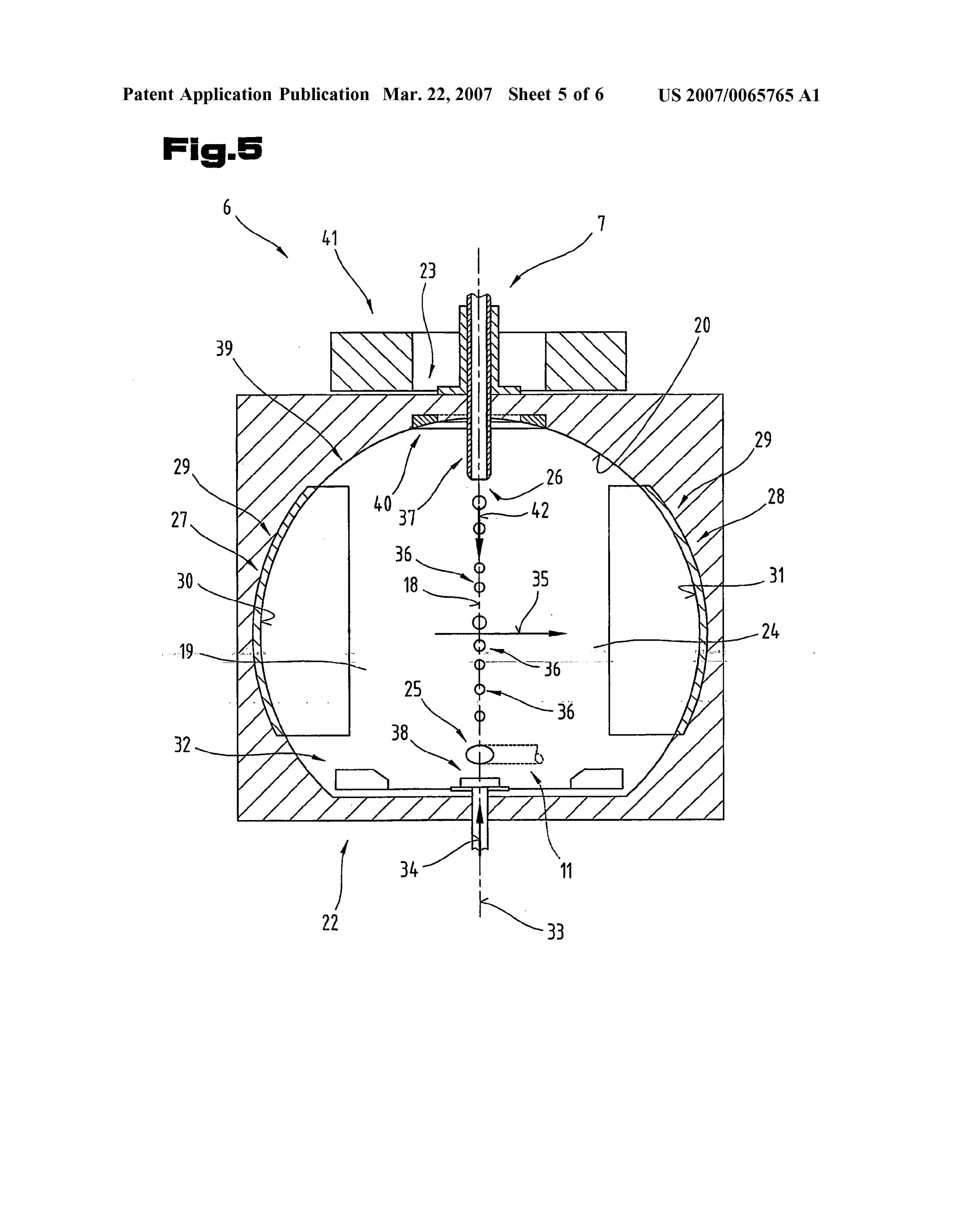
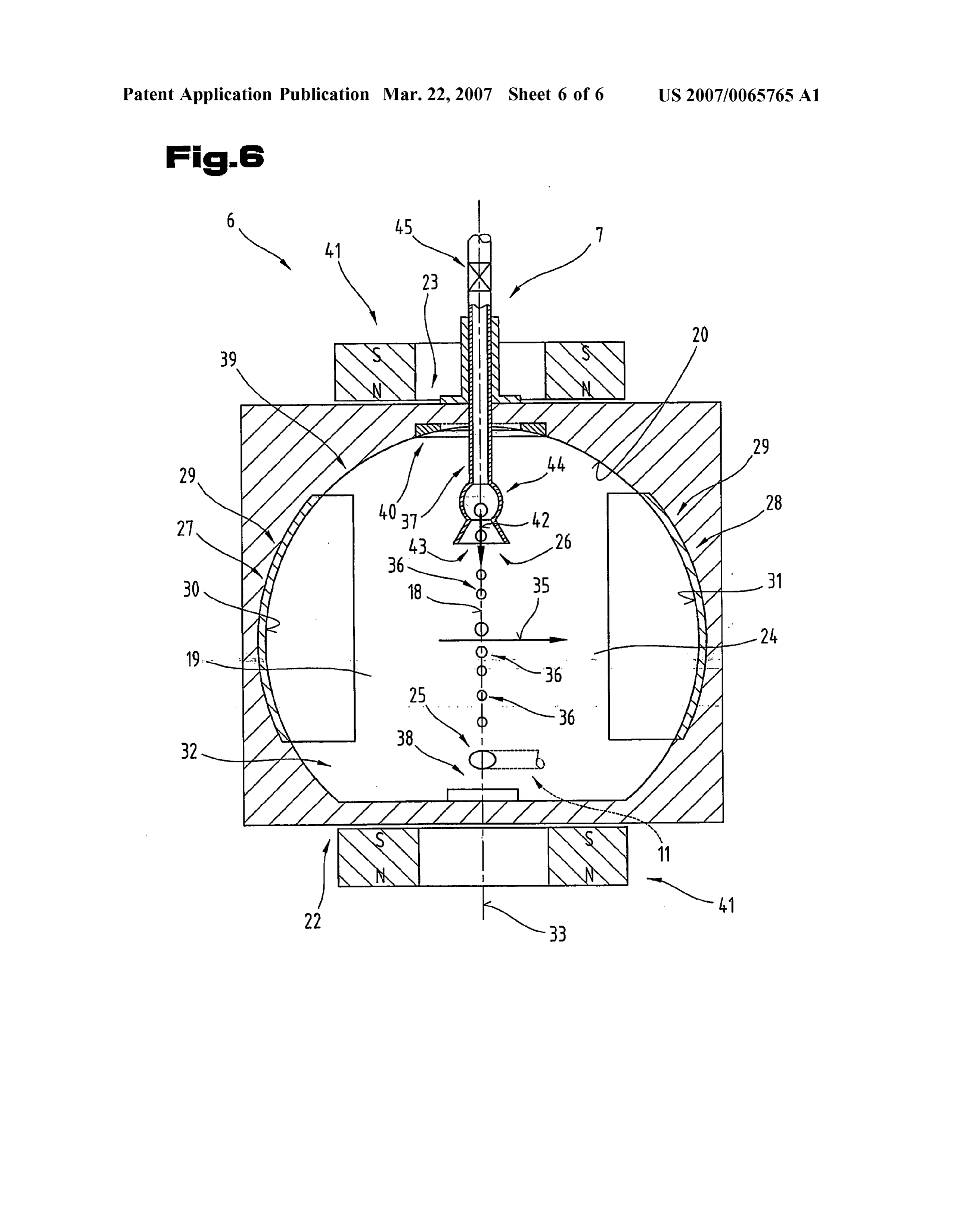
0014. The advantage of the embodiment of the device for 0023. Also of advantage is another embodiment of the converting energy with a pressure vessel for the working method, whereby the water and Brown gas are conveyed in medium is that the pressure of the working medium in the a closed circuit, because there is no need to disposed of device can be set to an optimum level, which is conducive residues, on the one hand, and electrolytes introducing into to the rate at which Brown gas forms. the working medium or water are not depleted, on the other hand.
0.015 Also of advantage is the embodiment of the device for converting energy in which it is provided in the form of 0024. The rate at which Brown gas forms can also a heating device incorporating a heat generator and the advantageously be increased by periodically varying the interior of the heat generator is provided or filled with a angular velocity of the rotation of the water in the reaction sintered material or sintered metal, because the recombina chamber or the pressure of the working medium in the tion or conversion into water during which no naked flame circuit or the acoustic intensity of a acoustic source. This is is formed takes place relatively slowly as the Brown gas also assisted by the fact that the periodic variation of the flows through this sintered material. pressure of the working medium takes place in opposite 0016. In another embodiment of the heating device, the phases with respect to the periodic variation in the acoustic gas generator, the heat generator, the heat exchanger, the intensity of the acoustic source and the value of the fre pressure vessel and the pump are connected to one another quency of the periodic variation in the pressure of the forming a closed circuit for the working medium, the working medium and/or acoustic intensity of the acoustic advantage of which is that the working medium can remain Source and/or the angular velocity is selected from of a range of between 0.1 HZ and 10 HZ.
in the circuit and there is no need to dispose of waste water or residues. In particular, this prevents any electrolytes 0025. Also of advantage is another embodiment of the introduced into the working medium from gradually being method, whereby the recombination of the hydrogen-oxygen depleted or lost. mixture or Brown gas into water takes place in a heat 0017. In another embodiment of the heating device, a fan generator, in which case the heat created by the heat gen is disposed on the heat exchanger for feeding heat away erator is fed away with the water, thereby obviating the need from the heat exchanger to the ambient environment, the for a separate medium to transport the heat. advantage of which is that the amount of heat emitted can be 0026. In another embodiment of the method, the Brown controlled by varying the quantity of air flowing past the gas is fed through a sintered material in the heat generator, heat exchanger. the advantage of which is that flames are prevented from 0018. In another embodiment, the device for converting forming during recombination of the Brown gas to water and energy has a control device for controlling the operating the transformation of the Brown gas into water takes place relatively slowly.
mode, the advantage of which is that all the parameters of the individual components of the device can be set centrally. 0027. To provide a clearer understanding, the invention 0019. Also of advantage is the embodiment of the control will be explained in more detail below with reference to the appended drawings.
device which operates controls on an automated or pro grammed basis, because the operating mode can be adjusted 0028. The schematically simplified diagrams of the draw and in particular adjusted Subsequently on an automated ings illustrated the following:
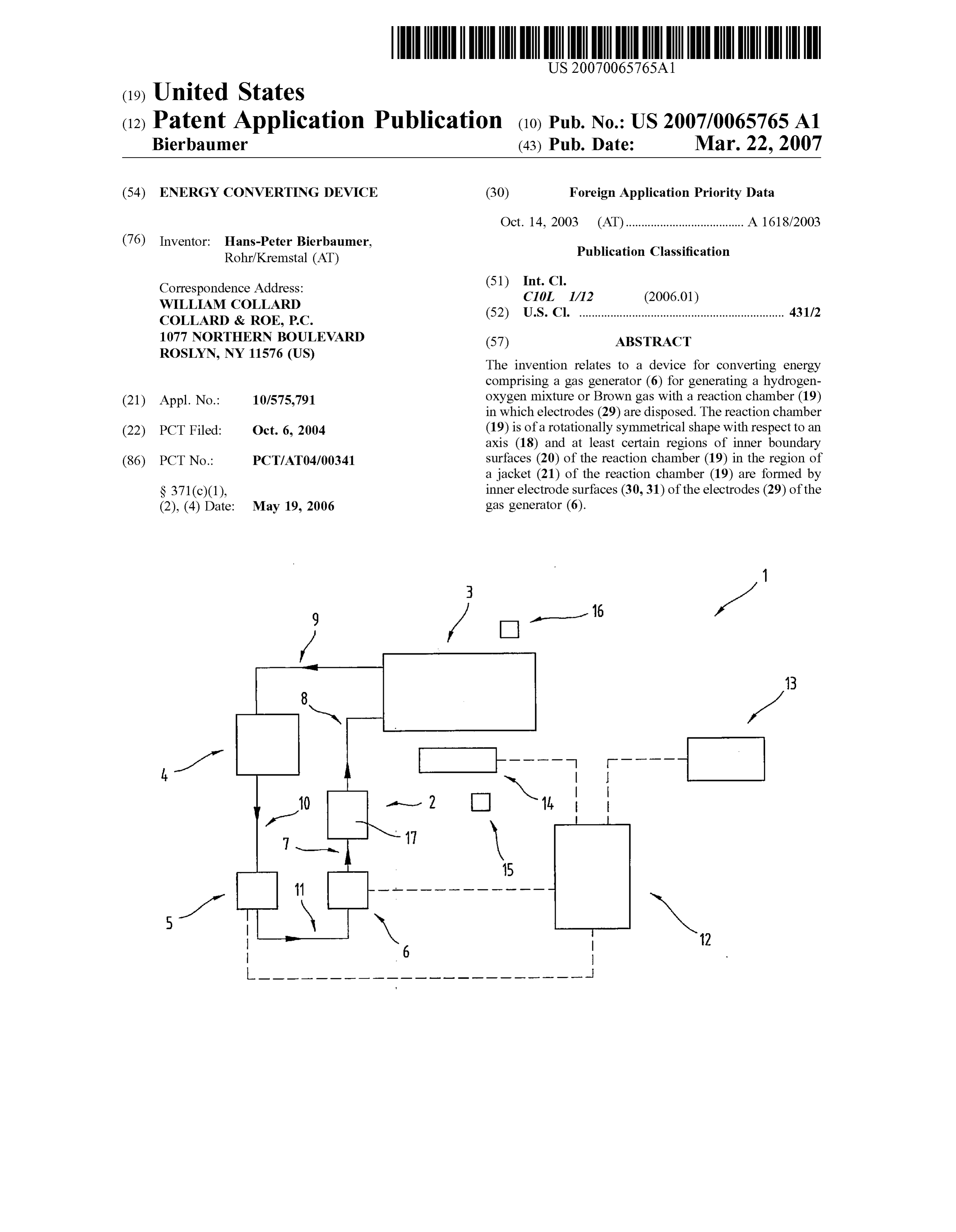
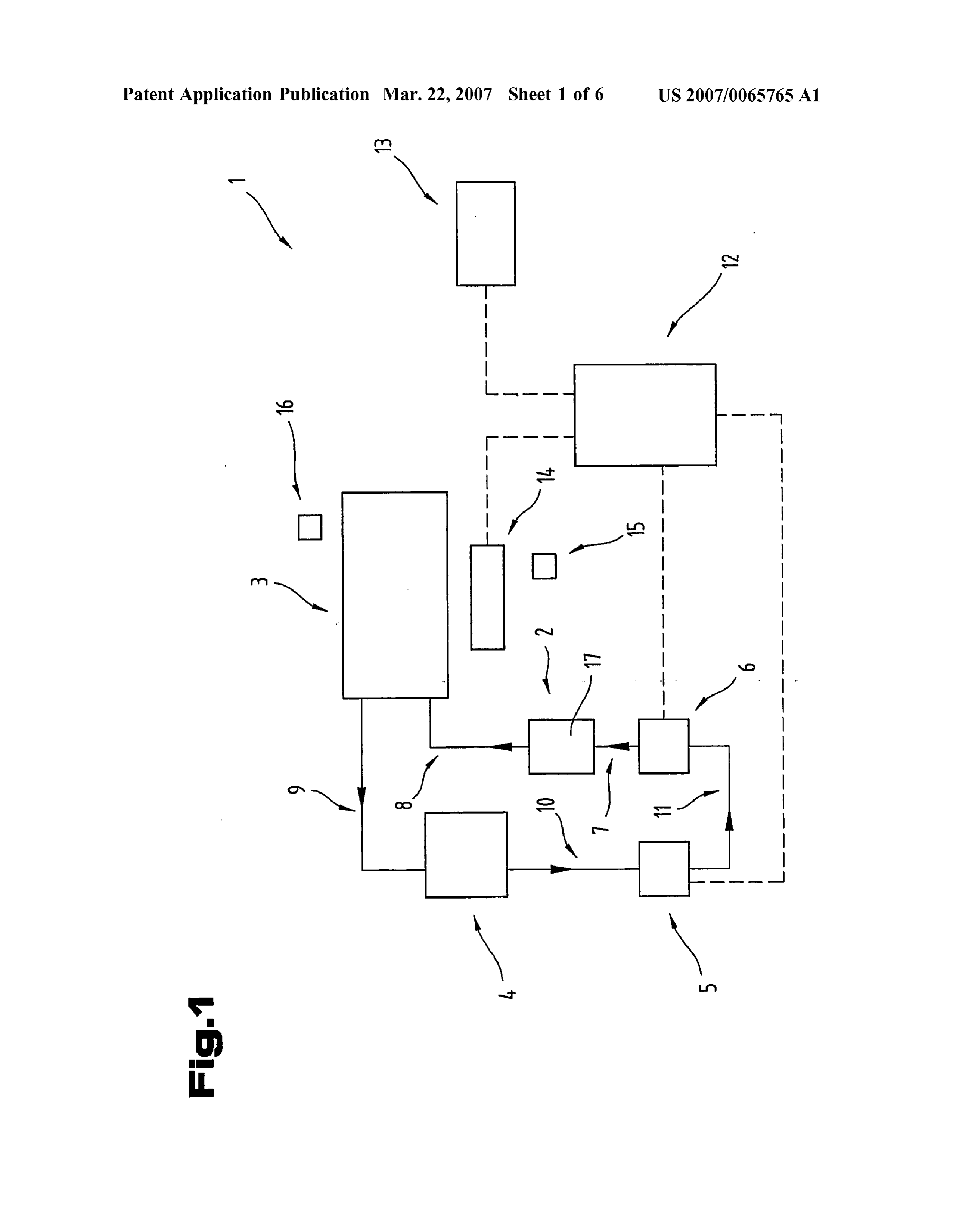
basis to produce an optimum yield of heat and form Brown 0029 FIG. 1 a system diagram of a heating device, gas automatically in the gas generator. illustrated in the form of a block diagram of an air heating 0020. The objective of the invention is also indepen system;
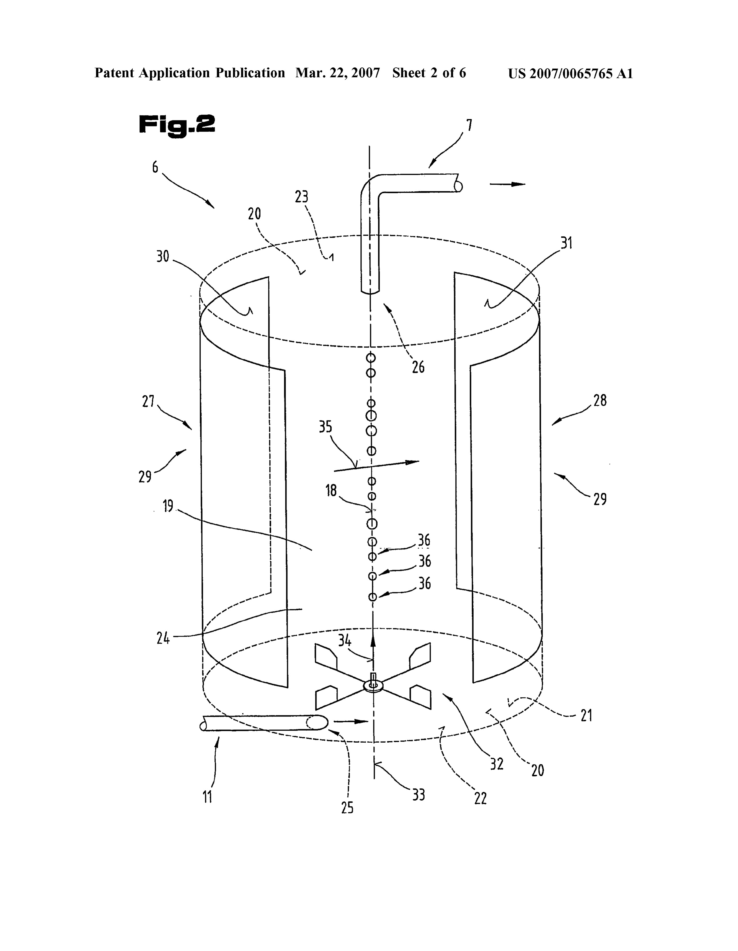
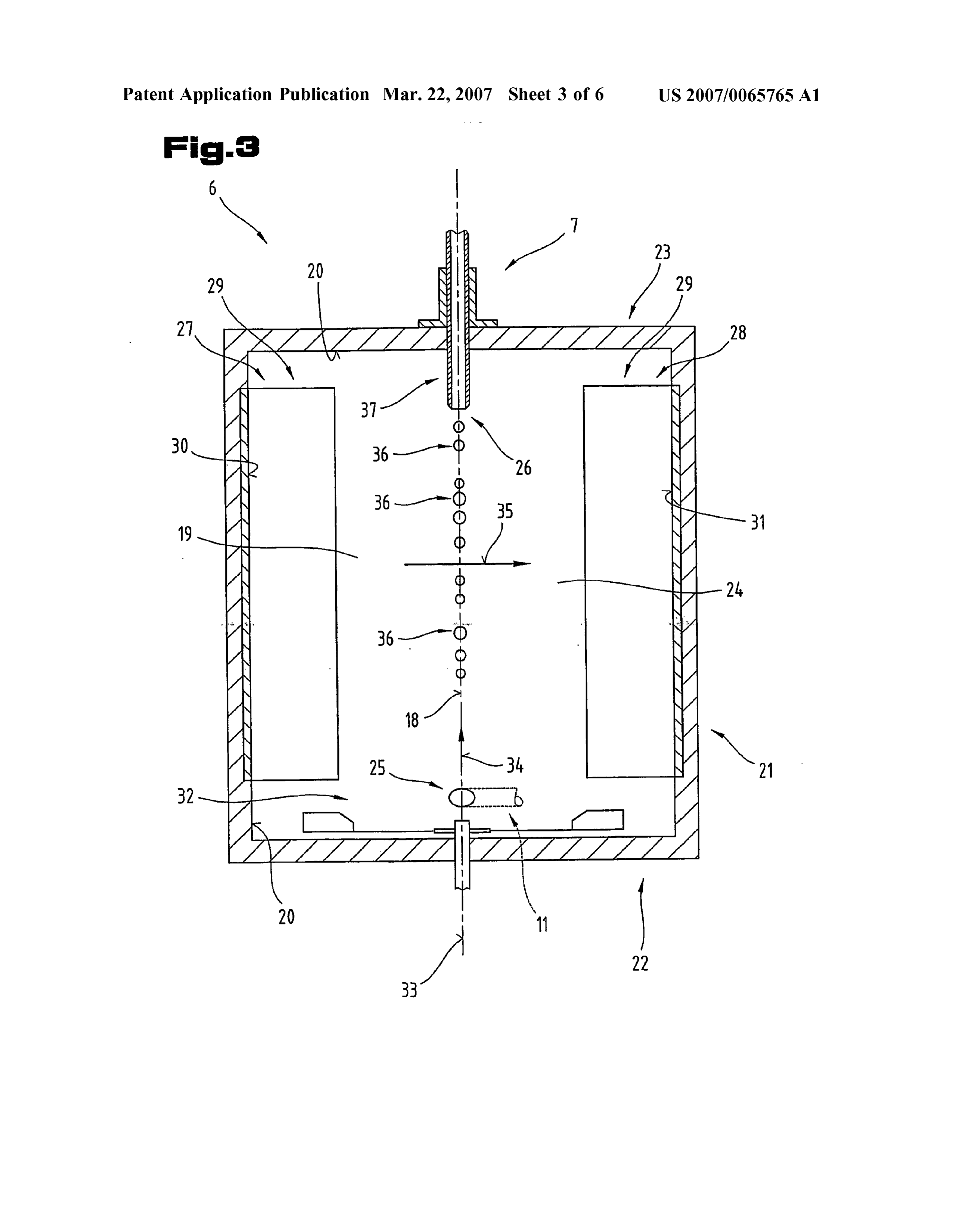
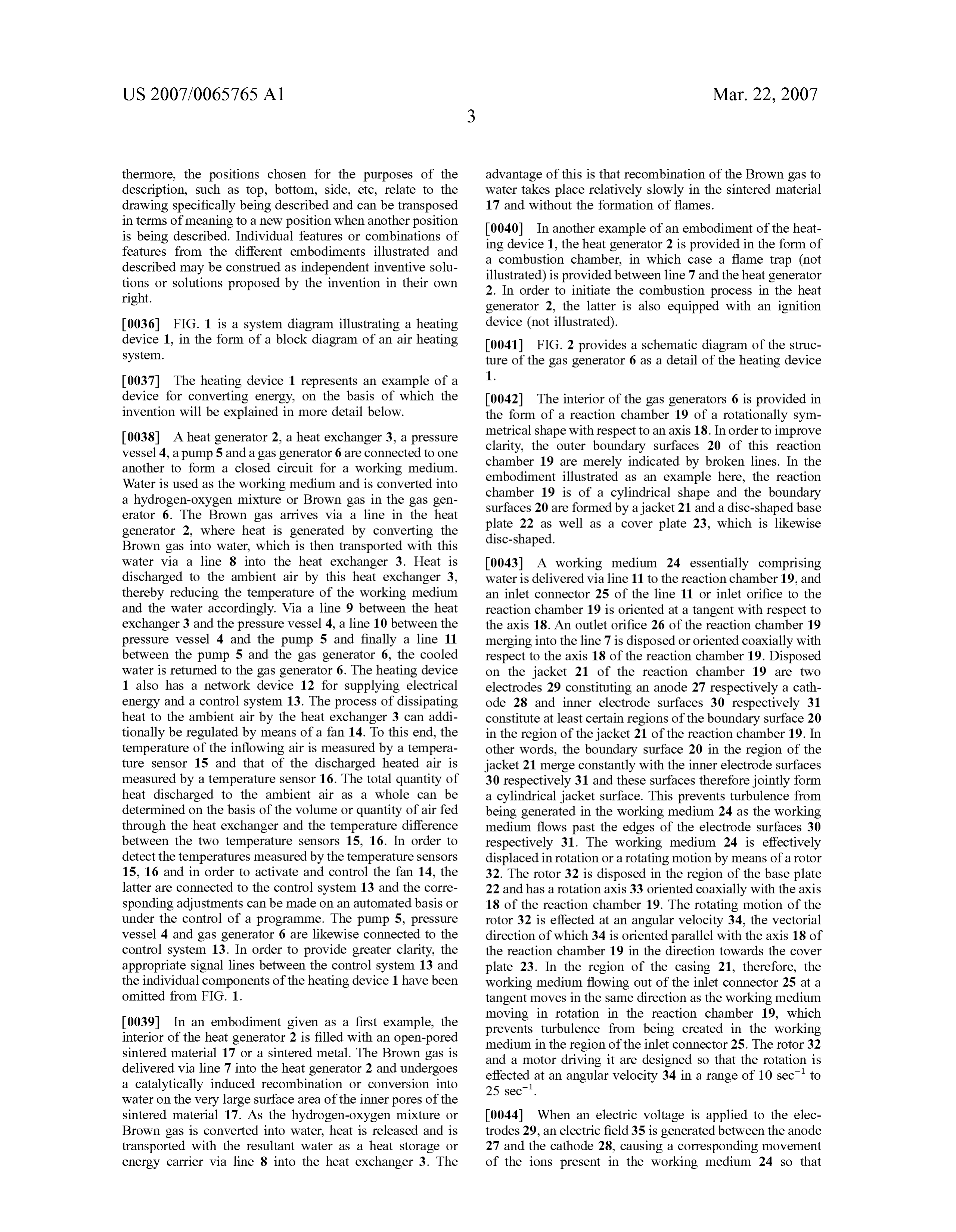
dently achieved by the method of converting energy using a 0030 FIG. 2 the schematically illustrated structure of the hydrogen-oxygen mixture or Brown gas incorporating the gas generator as a detail of the heating device; characterising features defined in claim 23. The advantage of this approach is that a higher degree of efficiency can be 0031 FIG.3 a section illustrating another example of an achieved with this method. embodiment of a gas generator of a heating device with a cylindrical reaction chamber, 0021. In one embodiment of the method, the water and/or
Brown gas is exposed to a magnetic field in the reaction 0032 FIG. 4 an example of an embodiment of the gas chamber, whereby the magnetic induction in the region of generator of the heating device with an acoustic source the axis of the reaction chamber is oriented anti-parallel with disposed in the reaction chamber; respect to the direction of the angular Velocity, the advantage 0033 FIG. 5 an example of another embodiment of the of which his that a force can be directed by the magnetic gas generator of the heating device with an infrared source field onto the ions disposed in the rotating working medium and a magnet;
in the direction towards the axis of the rotating motion, thereby promoting the formation of Brown gas in the region 0034 FIG. 6 an example of another embodiment of a gas of the axis of the rotating motion of the working medium. generator.
0022. In another embodiment of the method, the water 0035 Firstly, it should be pointed out that the same parts and/or Brown gas is exposed to acoustic energy in the described in the different embodiments are denoted by the reaction chamber or the water and/or Brown gas in the same reference numbers and the same component names and reaction chamber is exposed to infrared radiation, the advan the disclosures made throughout the description can be tage of which is that the rate at which Brown gas is formed transposed in terms of meaning to same parts bearing the increases. same reference numbers or same component names. Fur
Page 10
US 2007/0065765 A1 Mar. 22, 2007
thermore, the positions chosen for the purposes of the advantage of this is that recombination of the Brown gas to description, Such as top, bottom, side, etc., relate to the water takes place relatively slowly in the sintered material drawing specifically being described and can be transposed 17 and without the formation of flames. in terms of meaning to a new position when another position 0040. In another example of an embodiment of the heat is being described. Individual features or combinations of ing device 1, the heat generator 2 is provided in the form of features from the different embodiments illustrated and described may be construed as independent inventive solu a combustion chamber, in which case a flame trap (not tions or solutions proposed by the invention in their own illustrated) is provided between line 7 and the heat generator right. 2. In order to initiate the combustion process in the heat generator 2, the latter is also equipped with an ignition 0.036 FIG. 1 is a system diagram illustrating a heating device (not illustrated).
device 1, in the form of a block diagram of an air heating 0041 FIG. 2 provides a schematic diagram of the struc system. ture of the gas generator 6 as a detail of the heating device 0037. The heating device 1 represents an example of a 1.
device for converting energy, on the basis of which the 0042. The interior of the gas generators 6 is provided in invention will be explained in more detail below. the form of a reaction chamber 19 of a rotationally sym 0038 A heat generator 2, a heat exchanger 3, a pressure metrical shape with respect to an axis 18. In order to improve vessel 4, a pump 5 and a gas generator 6 are connected to one clarity, the outer boundary surfaces 20 of this reaction another to form a closed circuit for a working medium. chamber 19 are merely indicated by broken lines. In the Water is used as the working medium and is converted into embodiment illustrated as an example here, the reaction a hydrogen-oxygen mixture or Brown gas in the gas gen chamber 19 is of a cylindrical shape and the boundary erator 6. The Brown gas arrives via a line in the heat surfaces 20 are formed by a jacket 21 and a disc-shaped base generator 2, where heat is generated by converting the plate 22 as well as a cover plate 23, which is likewise Brown gas into water, which is then transported with this disc-shaped.
water via a line 8 into the heat exchanger 3. Heat is 0043 A working medium 24 essentially comprising discharged to the ambient air by this heat exchanger 3, water is delivered via line 11 to the reaction chamber 19, and thereby reducing the temperature of the working medium an inlet connector 25 of the line 11 or inlet orifice to the and the water accordingly. Via a line 9 between the heat reaction chamber 19 is oriented at a tangent with respect to exchanger 3 and the pressure vessel 4, a line 10 between the the axis 18. An outlet orifice 26 of the reaction chamber 19 pressure vessel 4 and the pump 5 and finally a line 11 merging into the line 7 is disposed or oriented coaxially with between the pump 5 and the gas generator 6, the cooled respect to the axis 18 of the reaction chamber 19. Disposed water is returned to the gas generator 6. The heating device on the jacket 21 of the reaction chamber 19 are two 1 also has a network device 12 for Supplying electrical electrodes 29 constituting an anode 27 respectively a cath energy and a control system 13. The process of dissipating ode 28 and inner electrode surfaces 30 respectively 31 heat to the ambient air by the heat exchanger 3 can addi constitute at least certain regions of the boundary surface 20 tionally be regulated by means of a fan 14. To this end, the in the region of the jacket 21 of the reaction chamber 19. In temperature of the inflowing air is measured by a tempera other words, the boundary surface 20 in the region of the ture sensor 15 and that of the discharged heated air is jacket 21 merge constantly with the inner electrode Surfaces measured by a temperature sensor 16. The total quantity of 30 respectively 31 and these surfaces therefore jointly form heat discharged to the ambient air as a whole can be a cylindrical jacket surface. This prevents turbulence from determined on the basis of the volume or quantity of air fed being generated in the working medium 24 as the working through the heat exchanger and the temperature difference medium flows past the edges of the electrode surfaces 30 between the two temperature sensors 15, 16. In order to respectively 31. The working medium 24 is effectively detect the temperatures measured by the temperature sensors displaced in rotation or a rotating motion by means of a rotor 15, 16 and in order to activate and control the fan 14, the 32. The rotor 32 is disposed in the region of the base plate latter are connected to the control system 13 and the corre 22 and has a rotation axis 33 oriented coaxially with the axis sponding adjustments can be made on an automated basis or 18 of the reaction chamber 19. The rotating motion of the under the control of a programme. The pump 5, pressure rotor 32 is effected at an angular velocity 34, the vectorial vessel 4 and gas generator 6 are likewise connected to the direction of which 34 is oriented parallel with the axis 18 of control system 13. In order to provide greater clarity, the the reaction chamber 19 in the direction towards the cover appropriate signal lines between the control system 13 and plate 23. In the region of the casing 21, therefore, the the individual components of the heating device 1 have been working medium flowing out of the inlet connector 25 at a omitted from FIG. 1. tangent moves in the same direction as the working medium 0039. In an embodiment given as a first example, the moving in rotation in the reaction chamber 19, which interior of the heat generator 2 is filled with an open-pored prevents turbulence from being created in the working sintered material 17 or a sintered metal. The Brown gas is medium in the region of the inlet connector 25. The rotor 32 delivered via line 7 into the heat generator 2 and undergoes and a motor driving it are designed so that the rotation is a catalytically induced recombination or conversion into effected at an angular velocity 34 in a range of 10 sec' to
water on the very large surface area of the inner pores of the sintered material 17. As the hydrogen-oxygen mixture or 0044) When an electric voltage is applied to the elec Brown gas is converted into water, heat is released and is trodes 29, an electric field 35 is generated between the anode transported with the resultant water as a heat storage or 27 and the cathode 28, causing a corresponding movement energy carrier via line 8 into the heat exchanger 3. The of the ions present in the working medium 24 So that
Page 11
US 2007/0065765 A1 Mar. 22, 2007
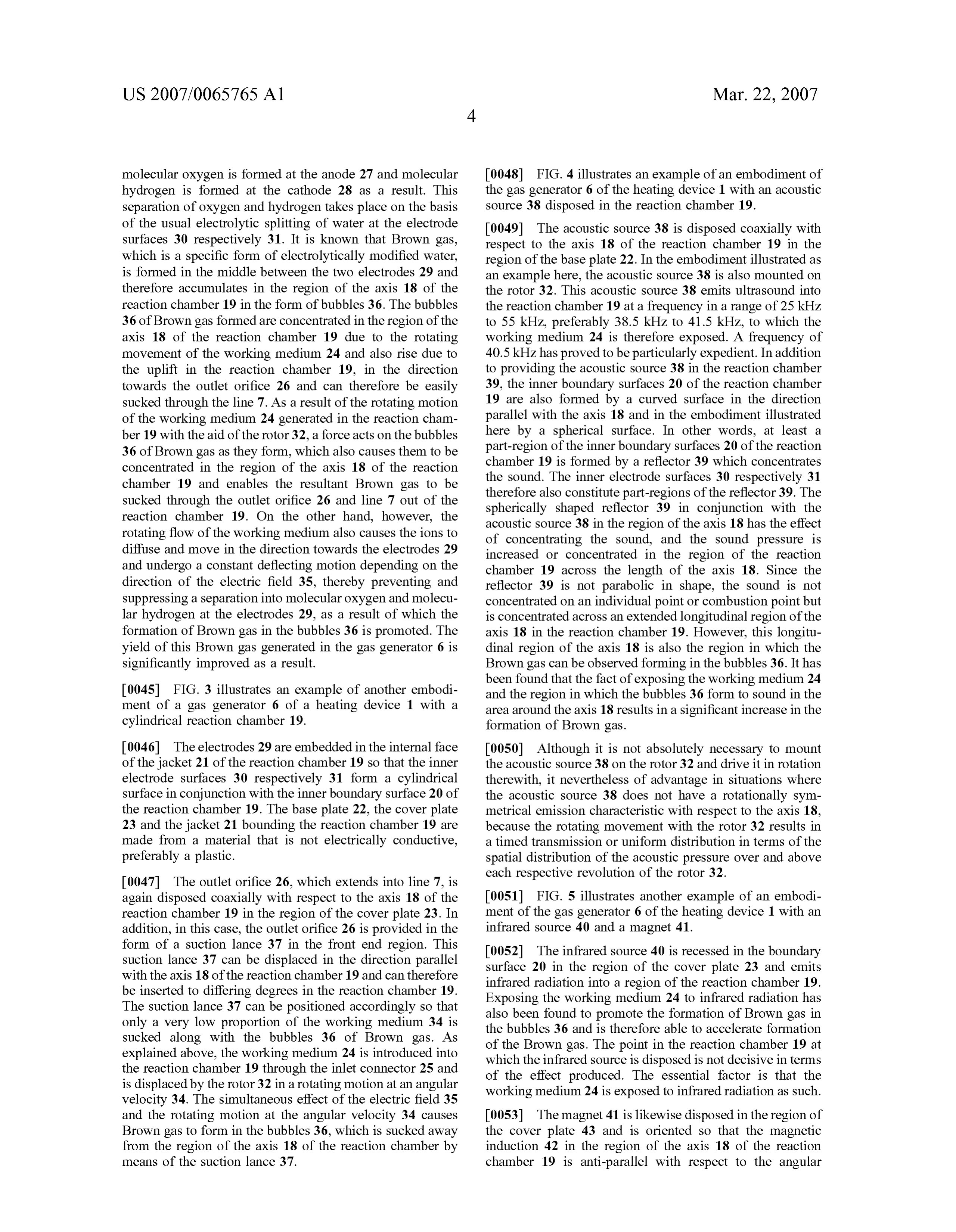
molecular oxygen is formed at the anode 27 and molecular 0048 FIG. 4 illustrates an example of an embodiment of hydrogen is formed at the cathode 28 as a result. This the gas generator 6 of the heating device 1 with an acoustic separation of oxygen and hydrogen takes place on the basis source 38 disposed in the reaction chamber 19. of the usual electrolytic splitting of water at the electrode 0049. The acoustic source 38 is disposed coaxially with surfaces 30 respectively 31. It is known that Brown gas, respect to the axis 18 of the reaction chamber 19 in the which is a specific form of electrolytically modified water, region of the base plate 22. In the embodiment illustrated as is formed in the middle between the two electrodes 29 and an example here, the acoustic Source 38 is also mounted on therefore accumulates in the region of the axis 18 of the the rotor 32. This acoustic source 38 emits ultrasound into reaction chamber 19 in the form of bubbles 36. The bubbles the reaction chamber 19 at a frequency in a range of 25 kHz 36 of Brown gas formed are concentrated in the region of the to 55 kHz, preferably 38.5 kHz to 41.5 kHz, to which the axis 18 of the reaction chamber 19 due to the rotating working medium 24 is therefore exposed. A frequency of movement of the working medium 24 and also rise due to 40.5 kHz has proved to be particularly expedient. In addition the uplift in the reaction chamber 19, in the direction to providing the acoustic source 38 in the reaction chamber towards the outlet orifice 26 and can therefore be easily 39, the inner boundary surfaces 20 of the reaction chamber sucked through the line 7. As a result of the rotating motion 19 are also formed by a curved surface in the direction of the working medium 24 generated in the reaction cham parallel with the axis 18 and in the embodiment illustrated ber 19 with the aid of the rotor 32, a force acts on the bubbles here by a spherical Surface. In other words, at least a 36 of Brown gas as they form, which also causes them to be part-region of the inner boundary surfaces 20 of the reaction concentrated in the region of the axis 18 of the reaction chamber 19 is formed by a reflector 39 which concentrates chamber 19 and enables the resultant Brown gas to be the sound. The inner electrode surfaces 30 respectively 31 sucked through the outlet orifice 26 and line 7 out of the therefore also constitute part-regions of the reflector 39. The spherically shaped reflector 39 in conjunction with the reaction chamber 19. On the other hand, however, the acoustic source 38 in the region of the axis 18 has the effect rotating flow of the working medium also causes the ions to of concentrating the Sound, and the sound pressure is diffuse and move in the direction towards the electrodes 29 increased or concentrated in the region of the reaction and undergo a constant deflecting motion depending on the chamber 19 across the length of the axis 18. Since the direction of the electric field 35, thereby preventing and reflector 39 is not parabolic in shape, the sound is not Suppressing a separation into molecular oxygen and molecu concentrated on an individual point or combustion point but lar hydrogen at the electrodes 29, as a result of which the is concentrated across an extended longitudinal region of the formation of Brown gas in the bubbles 36 is promoted. The axis 18 in the reaction chamber 19. However, this longitu yield of this Brown gas generated in the gas generator 6 is dinal region of the axis 18 is also the region in which the significantly improved as a result. Brown gas can be observed forming in the bubbles 36. It has been found that the fact of exposing the working medium 24 0045 FIG. 3 illustrates an example of another embodi and the region in which the bubbles 36 form to sound in the ment of a gas generator 6 of a heating device 1 with a area around the axis 18 results in a significant increase in the cylindrical reaction chamber 19. formation of Brown gas.
0046) The electrodes 29 are embedded in the internal face 0050 Although it is not absolutely necessary to mount of the jacket 21 of the reaction chamber 19 so that the inner the acoustic source 38 on the rotor 32 and drive it in rotation electrode surfaces 30 respectively 31 form a cylindrical therewith, it nevertheless of advantage in situations where surface in conjunction with the inner boundary surface 20 of the acoustic source 38 does not have a rotationally sym the reaction chamber 19. The base plate 22, the cover plate metrical emission characteristic with respect to the axis 18, 23 and the jacket 21 bounding the reaction chamber 19 are because the rotating movement with the rotor 32 results in made from a material that is not electrically conductive, a timed transmission or uniform distribution in terms of the preferably a plastic. spatial distribution of the acoustic pressure over and above each respective revolution of the rotor 32.
0047. The outlet orifice 26, which extends into line 7, is again disposed coaxially with respect to the axis 18 of the 0051 FIG. 5 illustrates another example of an embodi reaction chamber 19 in the region of the cover plate 23. In ment of the gas generator 6 of the heating device 1 with an addition, in this case, the outlet orifice 26 is provided in the infrared source 40 and a magnet 41. form of a suction lance 37 in the front end region. This 0052 The infrared source 40 is recessed in the boundary suction lance 37 can be displaced in the direction parallel surface 20 in the region of the cover plate 23 and emits with the axis 18 of the reaction chamber 19 and can therefore be inserted to differing degrees in the reaction chamber 19. infrared radiation into a region of the reaction chamber 19. The suction lance 37 can be positioned accordingly so that Exposing the working medium 24 to infrared radiation has only a very low proportion of the working medium 34 is also been found to promote the formation of Brown gas in the bubbles 36 and is therefore able to accelerate formation sucked along with the bubbles 36 of Brown gas. As of the Brown gas. The point in the reaction chamber 19 at explained above, the working medium 24 is introduced into which the infrared source is disposed is not decisive in terms the reaction chamber 19 through the inlet connector 25 and of the effect produced. The essential factor is that the is displaced by the rotor 32 in a rotating motion at an angular working medium 24 is exposed to infrared radiation as such. velocity 34. The simultaneous effect of the electric field 35 and the rotating motion at the angular Velocity 34 causes 0053. The magnet 41 is likewise disposed in the region of Brown gas to form in the bubbles 36, which is sucked away the cover plate 43 and is oriented so that the magnetic from the region of the axis 18 of the reaction chamber by induction 42 in the region of the axis 18 of the reaction means of the suction lance 37. chamber 19 is anti-parallel with respect to the angular
Page 12
US 2007/0065765 A1 Mar. 22, 2007
velocity 34 or with respect to its direction. The combined field from a magnet 41 or of infrared radiation from an effect of rotating the working medium 24 by means of the infrared source 40. The sound pressure from the acoustic rotor 32 and the electric field 35 causes ions in the working source 38 as well as the intensity of the infrared radiation medium 24 to be moved in more or less circular trajectories. from the infrared source 40 and the magnetic induction 42 Depending on the force exerted on charges moved in mag of the magnet 41 are set by the control system 13, preferably netic fields caused by the magnetic field, the magnetic under the control of a programme. induction oriented anti-parallel with respect to the angular 0057. It has also been found that the level of efficiency of velocity 34 causes an additional force which is directed the method for generating heat with Brown gas can be more or less in the direction towards the axis 18 of the reaction chamber 19. The effect of this additional force increased if the pressure of the working medium 24 in the causes the ions in the working medium 24 to be forced along circuit as well as the acoustic intensity of the acoustic source spiral paths, which become ever closer to the axis 18 of the 38 are varied so that they rise and fall over time between a reaction chamber 19. The force from the magnet 41 there minimum value and a maximum value, i.e. periodically, in fore has the effect of moving the ions in the working medium which case the change in pressure is effected in the opposite 24 onto the anode 27 and onto the cathode 28, where they cycle of the change in acoustic intensity. The change in the cause the formation of molecular oxygen and molecular rising and falling values of the pressure and the Sound hydrogen and also cause the ions to be concentrated in the intensity over time may be effected relatively slowly and the region of the axis 18, where the formation of Brown gas in value of the frequency of this change is in the range of between 0.1 Hz and 10 HZ.
the bubbles 36 is rendered more intensive as a result.
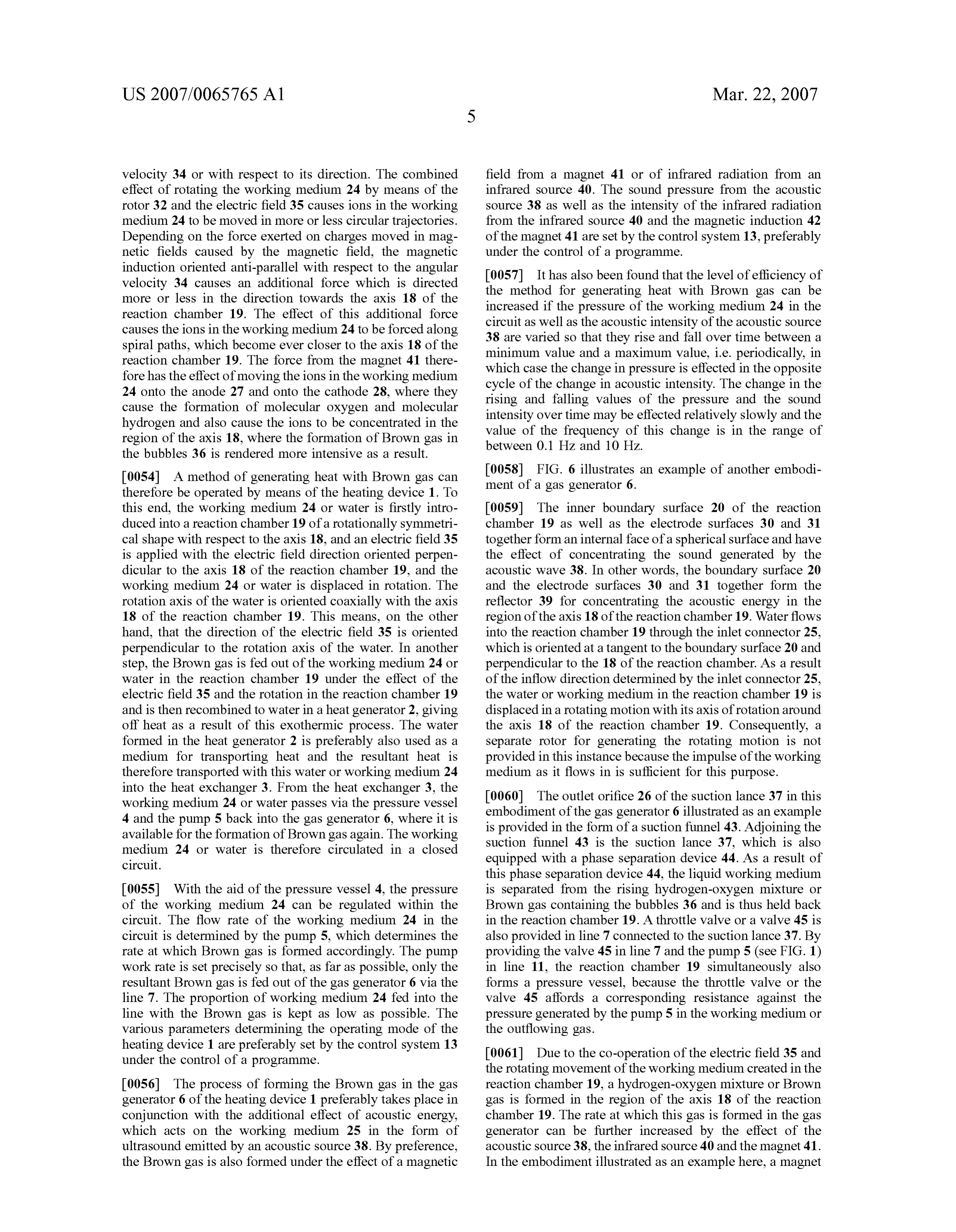
0054) A method of generating heat with Brown gas can 0058 FIG. 6 illustrates an example of another embodi therefore be operated by means of the heating device 1. To ment of a gas generator 6.
this end, the working medium 24 or water is firstly intro 0059) The inner boundary surface 20 of the reaction duced into a reaction chamber 19 of a rotationally symmetri chamber 19 as well as the electrode surfaces 30 and 31 cal shape with respect to the axis 18, and an electric field 35 together forman internal face of a spherical Surface and have is applied with the electric field direction oriented perpen the effect of concentrating the sound generated by the dicular to the axis 18 of the reaction chamber 19, and the acoustic wave 38. In other words, the boundary surface 20 working medium 24 or water is displaced in rotation. The and the electrode surfaces 30 and 31 together form the rotation axis of the water is oriented coaxially with the axis reflector 39 for concentrating the acoustic energy in the 18 of the reaction chamber 19. This means, on the other region of the axis 18 of the reaction chamber 19. Water flows hand, that the direction of the electric field 35 is oriented into the reaction chamber 19 through the inlet connector 25, perpendicular to the rotation axis of the water. In another which is oriented at a tangent to the boundary surface 20 and step, the Brown gas is fed out of the working medium 24 or perpendicular to the 18 of the reaction chamber. As a result water in the reaction chamber 19 under the effect of the of the inflow direction determined by the inlet connector 25, electric field 35 and the rotation in the reaction chamber 19 the water or working medium in the reaction chamber 19 is and is then recombined to water in a heat generator 2, giving displaced in a rotating motion with its axis of rotation around off heat as a result of this exothermic process. The water the axis 18 of the reaction chamber 19. Consequently, a formed in the heat generator 2 is preferably also used as a separate rotor for generating the rotating motion is not medium for transporting heat and the resultant heat is provided in this instance because the impulse of the working therefore transported with this water or working medium 24 medium as it flows in is sufficient for this purpose. into the heat exchanger 3. From the heat exchanger 3, the working medium 24 or water passes via the pressure vessel 0060. The outlet orifice 26 of the suction lance 37 in this 4 and the pump 5 back into the gas generator 6, where it is embodiment of the gas generator 6 illustrated as an example available for the formation of Brown gas again. The working is provided in the form of a suction funnel 43. Adjoining the medium 24 or water is therefore circulated in a closed suction funnel 43 is the suction lance 37, which is also circuit. equipped with a phase separation device 44. As a result of this phase separation device 44, the liquid working medium 0055 With the aid of the pressure vessel 4, the pressure is separated from the rising hydrogen-oxygen mixture or of the working medium 24 can be regulated within the Brown gas containing the bubbles 36 and is thus held back circuit. The flow rate of the working medium 24 in the in the reaction chamber 19. A throttle valve or a valve 45 is circuit is determined by the pump 5, which determines the also provided in line 7 connected to the suction lance 37. By rate at which Brown gas is formed accordingly. The pump providing the valve 45 in line 7 and the pump 5 (see FIG. 1) work rate is set precisely so that, as far as possible, only the in line 11, the reaction chamber 19 simultaneously also resultant Brown gas is fed out of the gas generator 6 via the forms a pressure vessel, because the throttle valve or the line 7. The proportion of working medium 24 fed into the valve 45 affords a corresponding resistance against the line with the Brown gas is kept as low as possible. The pressure generated by the pump 5 in the working medium or various parameters determining the operating mode of the the outflowing gas.
heating device 1 are preferably set by the control system 13 0061 Due to the co-operation of the electric field 35 and under the control of a programme. the rotating movement of the working medium created in the 0056. The process of forming the Brown gas in the gas reaction chamber 19, a hydrogen-oxygen mixture or Brown generator 6 of the heating device 1 preferably takes place in gas is formed in the region of the axis 18 of the reaction conjunction with the additional effect of acoustic energy, chamber 19. The rate at which this gas is formed in the gas which acts on the working medium 25 in the form of generator can be further increased by the effect of the ultrasound emitted by an acoustic source 38. By preference, acoustic source 38, the infrared source 40 and the magnet 41. the Brown gas is also formed under the effect of a magnetic In the embodiment illustrated as an example here, a magnet
Page 13
US 2007/0065765 A1 Mar. 22, 2007
41 is provided both in the region of the cover plate 23 and 0081 15 Temperature sensor 40 Infrared source in the region of the base plate 22, as a result of which the 0082) 16 Temperature sensor 41 Magnet magnetic field or the magnetic induction 42 assumes a more homogeneous course in the region of the axis 18 of the 0083) 17 Sintered material 42 Induction reaction chamber 19.
0084 18 Axis 43 Suction funnel 0062) The gas generator 6 in this example is a constituent 0085) 19 Reaction chamber 44 Phase separation device part of a device for converting energy and the working medium or water in this instance is not circulated in a closed 0.086 20 Boundary surface 45 Valve circuit. The hydrogen-oxygen mixture or Brown gas gener 0.087 21 Jacket ated by the gas generator 6 is used for welding. Once the hydrogen-oxygen mixture or Brown gas has been combusted 0088 22 Base plate in the flame of the welding torch, the resultant water vapour 0089) 23 Cover plate is given off to the ambient environment.
0063. The embodiments illustrated as examples illustrate 0090) 24 Working medium possible design variants of the device for converting energy, 0091) 25 Inlet connector and it should be pointed out at this stage that the invention is not restricted to the various embodiments specifically 1-34. (canceled) illustrated and instead, various combinations of the indi 35. Device for converting energy comprising a gas gen vidual embodiments with one another are possible, these erator (6) for generating a hydrogen-oxygen mixture or possible variations being within the reach of the person Brown gas with a reaction chamber (19), in which electrodes skilled in this field based on the technical teaching outlined (29) are disposed, wherein the reaction chamber (19) is of a in the invention. Accordingly, all conceivable variations rotationally symmetrical shape with respect to an axis (18), which can be obtained by combining individual details of and at least certain regions of the inner boundary Surfaces the embodiments illustrated and described are possible and (20) of the reaction chamber (19) in the region of a jacket fall within the scope of the invention. (21) of the reaction chamber (19) are formed by inner 0064. For the sake of good order, finally, it should be electrode surfaces (30, 31) of the electrodes (29) of the gas pointed out that in order to provide a clearer understanding generator (6), wherein a rotor (32) with a rotation axis (33) of the device for converting energy, it and its constituent is provided in the gas generator (6) and the rotation axis (33) parts are illustrated to a certain extent out of Scale and/or on is oriented coaxially with the axis (18) of the reaction an enlarged scale and/or on a reduced scale. chamber (19).
36. Device as claimed in claim 35, wherein at least one 0065. The underlying objective and the solutions pro inlet connector (25) for a working medium (24) is provided posed by the invention may be found in the description. in the jacket (21), oriented at a tangent with respect to the 0.066 Above all, the individual embodiments of the sub jacket (21) of the reaction chamber (19). ject matter illustrated in FIGS. 1; 2: 3: 4; 5 and 6 may be 37. Device as claimed in claim 36, wherein the rotor (32) construed as independent solutions proposed by the inven is designed to generate a rotation with an angular Velocity tion in their own right. The objectives and associated Solu (34) in a range of from 10 S-1 to 25 s-1. tions proposed by the invention may be found in the detailed 38. Device as claimed in claim 35, wherein an outlet descriptions of these drawings. orifice (26) is provided in a base plate (22) and/or cover plate (23) closing off the reaction chamber (19) and the outlet
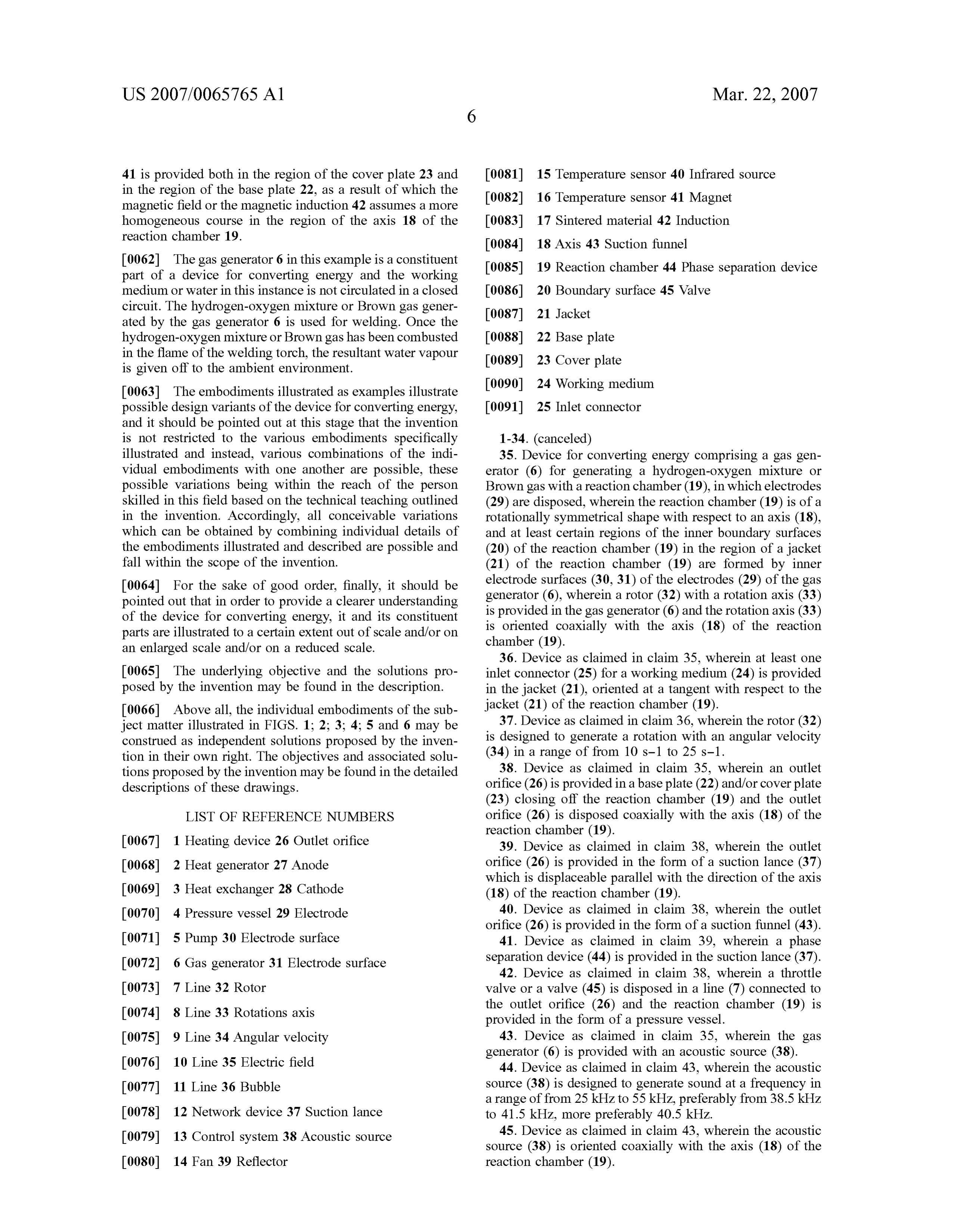
LIST OF REFERENCE NUMBERS orifice (26) is disposed coaxially with the axis (18) of the reaction chamber (19).
0067. 1 Heating device 26 Outlet orifice 39. Device as claimed in claim 38, wherein the outlet 0068 2 Heat generator 27 Anode orifice (26) is provided in the form of a suction lance (37) which is displaceable parallel with the direction of the axis 0069) 3 Heat exchanger 28 Cathode (18) of the reaction chamber (19). 0070 4 Pressure vessel 29 Electrode 40. Device as claimed in claim 38, wherein the outlet orifice (26) is provided in the form of a suction funnel (43).
0071 5 Pump 30 Electrode surface 41. Device as claimed in claim 39, wherein a phase 0072 6 Gas generator 31 Electrode surface separation device (44) is provided in the suction lance (37). 42. Device as claimed in claim 38, wherein a throttle 0073) 7 Line 32 Rotor valve or a valve (45) is disposed in a line (7) connected to 0074) 8 Line 33 Rotations axis the outlet orifice (26) and the reaction chamber (19) is provided in the form of a pressure vessel.
0075) 9 Line 34 Angular velocity 43. Device as claimed in claim 35, wherein the gas generator (6) is provided with an acoustic source (38).
0076) 10 Line 35 Electric field 44. Device as claimed in claim 43, wherein the acoustic 0.077 11 Line 36 Bubble Source (38) is designed to generate sound at a frequency in a range of from 25 kHz to 55 kHz, preferably from 38.5 kHz 0078 12 Network device 37 Suction lance to 41.5 kHz, more preferably 40.5 kHz. 0079 13 Control system 38 Acoustic source 45. Device as claimed in claim 43, wherein the acoustic source (38) is oriented coaxially with the axis (18) of the 0080 14 Fan 39 Reflector reaction chamber (19).
Page 14
US 2007/0065765 A1 Mar. 22, 2007
46. Device as claimed in claim 43, wherein at least a 57. Method as claimed in claim 56, wherein the water part-region of the inner boundary surface (20) of the reaction and/or Brown gas in the reaction chamber (19) is exposed to chamber (19) is shaped as a reflector (39) for concentrating a magnetic field, and a magnetic induction (42) in the region the Sound. of the axis (18) of the reaction chamber (19) is oriented 47. Device as claimed in claim 35, wherein the gas anti-parallel with respect to the direction of the angular generator (6) is provided with an IR source. velocity (34).
48. Device as claimed in claim 35, wherein the gas 58. Method as claimed in claim 56, wherein the water generator (6) is provided with a magnet (41). and/or Brown gas is exposed to acoustic energy in the 49. Device as claimed in claim 48, wherein a magnetic reaction chamber (19).
field direction of the magnet in the region of the axis (18) of 59. Method as claimed in claim 56, wherein the water the reaction chamber (19) is oriented anti-parallel with and/or Brown gas is exposed to IR radiation in the reaction respect to a direction of an angular velocity (34) of the rotor chamber (19).
50. Device as claimed in 35, wherein a pressure vessel (4) 60. Method as claimed in claim 56, wherein the water and is provided for the working medium (24). Brown gas are conveyed in a closed circuit. 51. Device as claimed in claim 35, wherein it is designed 61. Method as claimed in claim 56, wherein an angular as a heating device (1) with a heat generator (2) and an velocity (34) of the rotation of the water in the reaction interior of the heat generator (2) is provided with a sintered chamber (19) is periodically varied. material (17). 62. Method as claimed in claim 56, wherein a pressure of 52. Device as claimed in claim 51, wherein the gas the working medium (24) in the circuit is periodically generator (6), the heat generator (2), a heat exchanger (3), varied.
the pressure vessel (4) and a pump (5) are connected to one 63. Method as claimed in claim 56, wherein an acoustic another to form a closed circuit for the working medium intensity of an acoustic source (38) in the reaction chamber (24). (19) is periodically varied.
53. Device as claimed in claim 52, wherein a fan (14) is 64. Method as claimed in claim 63, wherein the periodic provided on the heat exchanger (3) for feeding heat away variation in the pressure of the working medium (24) from the heat exchanger (3).
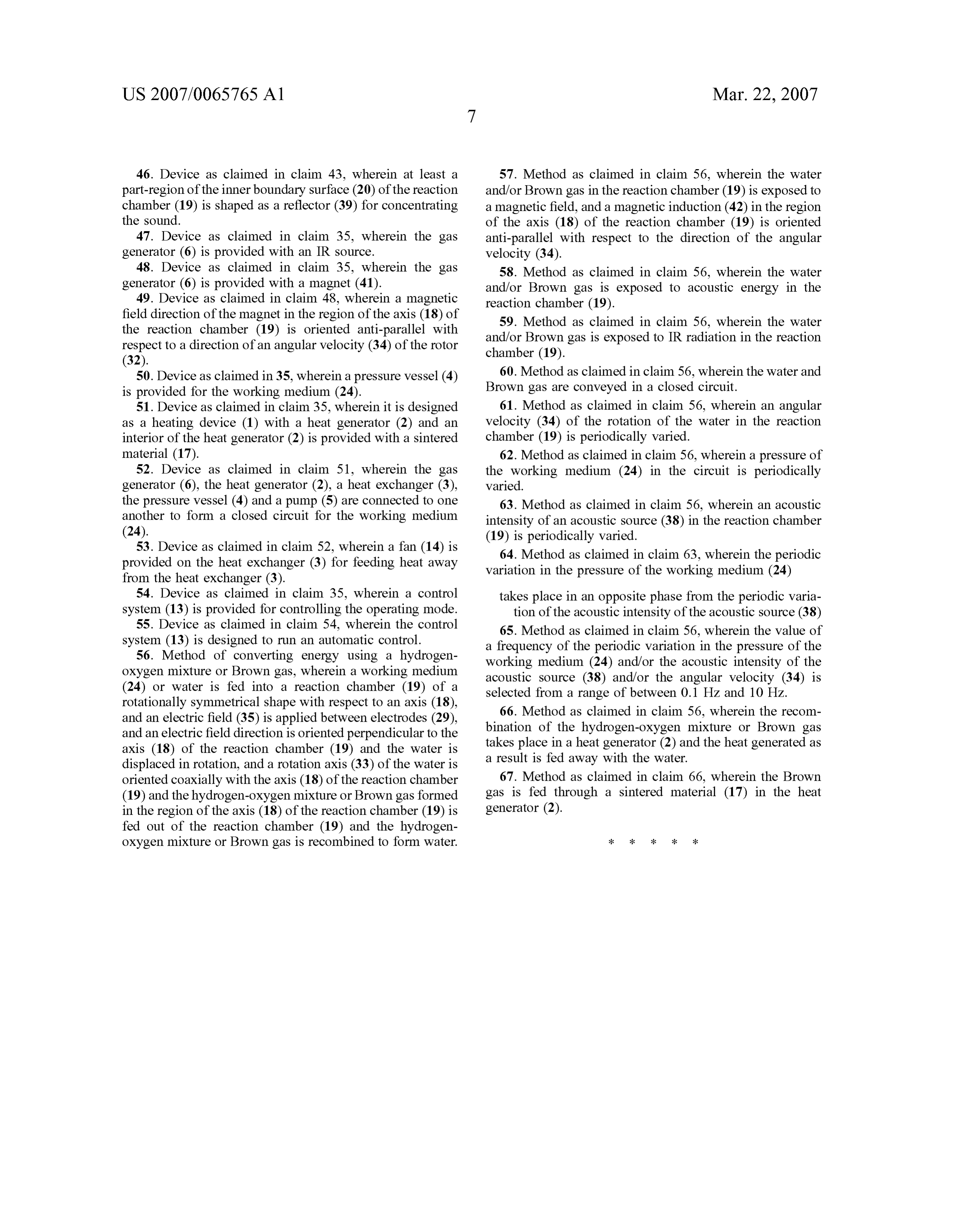
54. Device as claimed in claim 35, wherein a control takes place in an opposite phase from the periodic varia system (13) is provided for controlling the operating mode. tion of the acoustic intensity of the acoustic source (38) 55. Device as claimed in claim 54, wherein the control 65. Method as claimed in claim 56, wherein the value of system (13) is designed to run an automatic control. a frequency of the periodic variation in the pressure of the 56. Method of converting energy using a hydrogen working medium (24) and/or the acoustic intensity of the oxygen mixture or Brown gas, wherein a working medium acoustic source (38) and/or the angular velocity (34) is (24) or water is fed into a reaction chamber (19) of a selected from a range of between 0.1 Hz and 10 Hz. rotationally symmetrical shape with respect to an axis (18), and an electric field (35) is applied between electrodes (29), 66. Method as claimed in claim 56, wherein the recom and an electric field direction is oriented perpendicular to the bination of the hydrogen-oxygen mixture or Brown gas axis (18) of the reaction chamber (19) and the water is takes place in a heat generator (2) and the heat generated as displaced in rotation, and a rotation axis (33) of the water is a result is fed away with the water. oriented coaxially with the axis (18) of the reaction chamber 67. Method as claimed in claim 66, wherein the Brown (19) and the hydrogen-oxygen mixture or Brown gas formed gas is fed through a sintered material (17) in the heat in the region of the axis (18) of the reaction chamber (19) is generator (2).
fed out of the reaction chamber (19) and the hydrogen oxygen mixture or Brown gas is recombined to form water.
Provenance
- Collection
- Patents citing this work
- Pages
- 14
- Method
- pdftotext (the PDF's own text layer) + pdftoppm 300dpi page scans
- Patent office record
- patents.google.com →
- Source
- Google Patents citing-documents table
- Assignee
- Hans-Peter Bierbaumer
- Inventors
- Hans-Peter Bierbaumer
- Published
- 2007-03-22
- Transcribed from
- patentimages.storage.googleapis.com →