patent · US3988166
Apparatus for enhancing the output of photovoltaic solar cells
26 October 1976
Page 1 — bibliographic record
United States Patent (19) [11] 3,988,166 Beam (45) Oct. 26, 1976 (54) APPARATUS FOR ENHANCING THE E. L. Ralph, "Use of Concentrated Sunlight with Solar OUTPUT OF PHOTOVOLTAIC SOLAR Cells for Terrestrial Applications,' Solar Energy, vol. CELLS 10, No. 2, pp. 67-71.
(75 Inventor: Benjamin H. Beam, Sunnyvale, W. A. Beckman et al., “Design Considerations for a Calif. 50 Watt Photovoltaic Power System Using Concen trated Solar Energy,” Solar Energy, vol. 10, No. 3, 73) Assignee: Beam Engineering, Inc., Sunnyvale, 1966, pp. 132-136. ,
Calif.
22 Filed: Jan. 7, 1975 Primary Examiner-John H. Mack Assistant Examiner-Aaron Weisstuch (21) Appl. No.: 539,065 Attorney, Agent, or Firm-Thomas H. Olson (52) U.S. Cl.................................... 136789; 126/271 (57) ABSTRACT 51) Int. C.’....................... H01L 31/04; F24J 3/02 An array of photovoltaic cells and a parabolic concen 58 Field of Search ............... 136/89; 126/270, 27 trator for concentrating solar energy onto the cells. A (56) References Cited watertight chamber including a solar energy pervious window adjacent the focus of the parabolic concentra
UNITED STATES PATENTS tor. The solar cell array is disposed within the cham 1,289,369 12/1918 Berglund............................... 136189 ber in alignment with the window. A quantity of water 2,402,662 6/1946 Ohl....................................... 136189 disposed in the chamber, the quantity being sufficient 2,888,007 5/1959 Tabor ................................. 126/270 to absorb heat energy so as to limit the temperature 2,946,945 7/1960 Regnier et al........................ 136189 rise of the solar cell array during periods of solar en 2,985,783 5/1961 Garbuny et al....................... 3.13165 ergy impingement thereon. The watertight chamber 3, 171403 3/1965 Drescher............................. 126/270 has sufficient external surface area that the heat en OTHER PUBLICATIONS ergy stored therein is transferred away during non C. Pfeiffer et al., “Performance of Silicon Solar Cells solar energy producing periods of the diurnal cycle. at High Levels of Solar Radiation,” Journal of Eng. for 2 Claims, 6 Drawing Figures

Page 2
Drawing sheet — no readable text.
Page 3
Drawing sheet — no readable text.
Page 4
a quantity of heat absorbing medium, such as water,
APPARATUS FOR ENHANCING THE OUTPUT OF which quantity is large enough to absorb sufficient heat PHOTOVOLTAIC SOLAR CELLS energy to limit the temperature rise during daylight BACKGROUND OF THE INVENTION hours. During the balance of the diurnal cycle when there is no sunlight, the heat energy is transferred to the 1. Field of the invention: relatively colder environment so as to operate the cells This invention relates to generation of electrical en at high efficiency without expending power for pump ergy from solar cells and more particularly to a method ing the medium through a conventional heat exchange and apparatus for enhancing the efficiency of energy system.
production to render solar cells competitive with more 10 Another object is to provide a very economical conventional sources of power. source of electric power by increasing the power that a 2. Description of the Prior Art: solar cell array can produce by orders of magnitude, In an article titled “Design Considerations for a 50 thus reducing the cost of power so produced to a point watt Photovoltaic Power System Using Concentrated where it becomes competitive with other sources of Solar Energy' by Beckman et al., published in Solar 15 energy. This object is achieved in part because the heat Energy, Volume 10, No. 3, 1966 at Page 132 et seq., energy absorbing medium, water, is universally avail there is disclosed a solar cell array on which solar en able and is exploited in a relatively simple inexpensive ergy is concentrated and wherein the cells are sup structure provided according to the invention. ported on a cooling unit which is part of a forced flow A futher object is to provide improved efficiency of water system that has a heat exchanger remote from 20 power generation from solar cells by providing a system the solar cells. The device disclosed in the article oper that exploits temperature conditions throughout the ates by transferring heat out of the system simulta diurnal cycle so that heat is absorbed in the medium neously with the heat input from the solar energy col during daylight hours and is released more efficiently lector and thus requires substantial pumping and heat during cooler periods in the diurnal cycle. exchanging capacity. 25 Still another object of the invention is to provide an An article titled “Performance of Silicon Solar Cells improved solar photovoltaic power supply which can at High Levels of Solar Radiation' by Pfeiffer et al., operate without attention and which requires only oc Transactions of the ASME, January, 1962, Page 33 et casional maintenance such as cleaning of the reflective seq., describes an experiment in which solar cells are surface. The present invention achieves this object by placed in a waterproof capsule that has a mylar window 30 providing apparatus that has a minimum number of through which solar energy is introduced. The water is moving parts so that breakdowns due to wear are mini circulated through the system at a substantial rate to mized or eliminated.
maintain a relatively low cell temperature. Yet another object of the invention is to provide a An article titled "Use of Concentrated Sunlight with 35 method for operating a solar cell which method contin Solar Cells for Terrestrial Applications' by Ralph, ues throughout the diurnal cycle. Performance of the Solar Energy, Volume 10, No. 2, 1966 Page 67 et seq., method permits elimination or reduction of power con discloses a solar concentrator for solar cells operating suming and wear producing parts and mechanisms. without auxiliary cooling equipment to offset tempera The foregoing together with other objects, features ture rise in the solar cells. He states that “Forced-air or and advantages will be more apparent after referring to water-cooling equipment could be used to offset this 40 the following specification and the accompanying temperature rise; however, such equipment is costly, drawings.
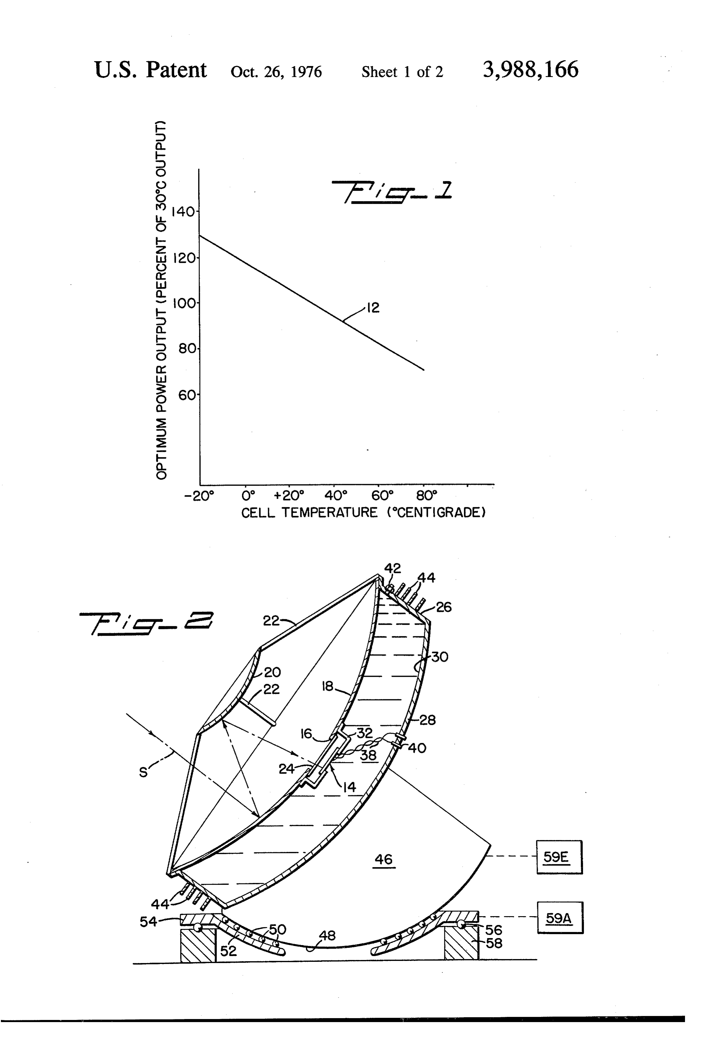
complicated, and would consume power, . . .' BRIEF DESCRIPTION OF THE DRAWINGS The following U.S. Pat. together with other Patents in
Class 136-89 disclose solar energy concentrators: Nos. 45 FIG. 1 is a plot of cell temperature versus power 588,177; 3,232,795; 3,279.457; 3,350,234; 3,376,165; output for a typical solar cell. 3,419,434; and 3,427,200. FIG. 2 is a cross sectional elevation view of an appa
SUMMARY OF THE INVENTION
ratus designed according to the present invention.
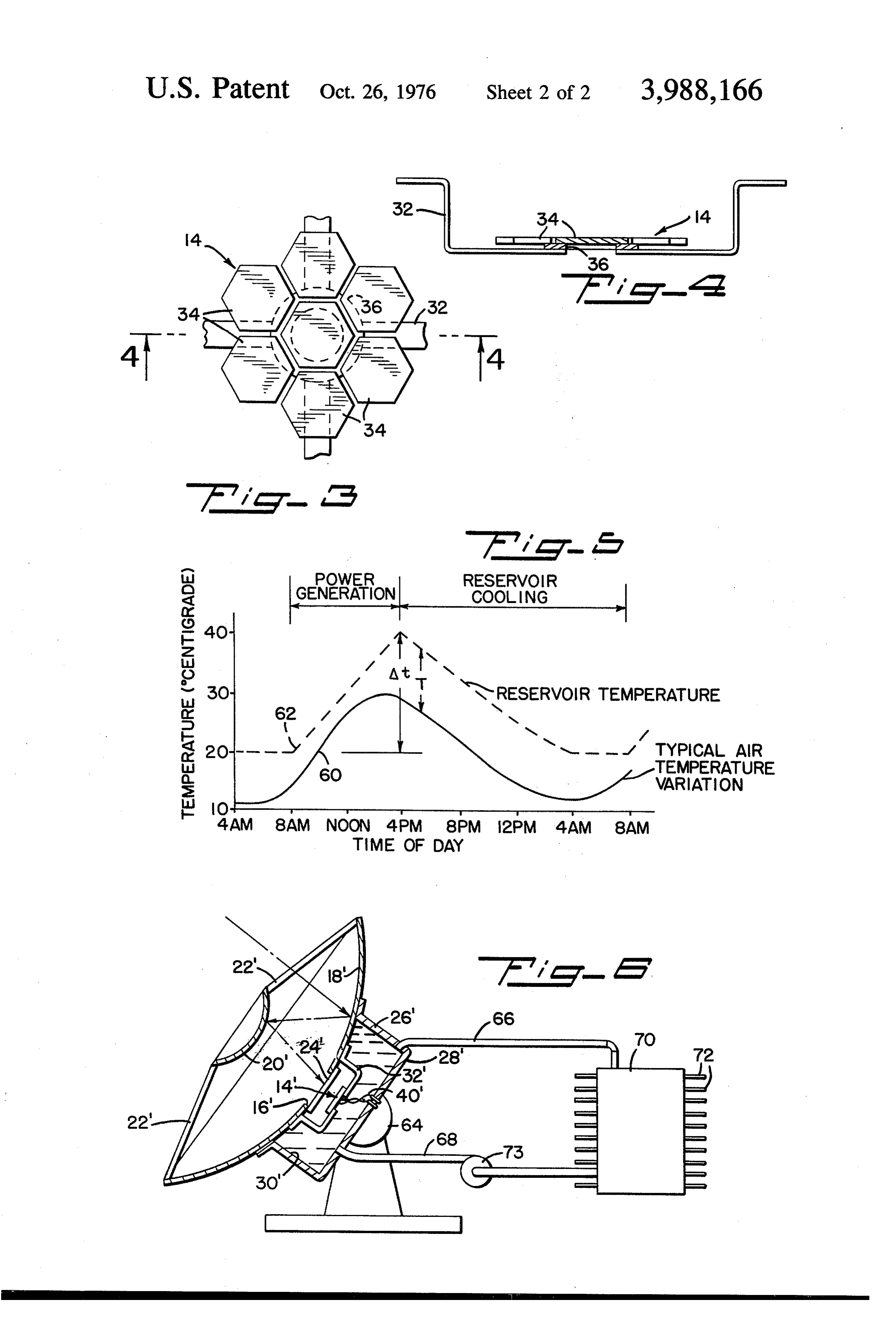
FIG. 3 is a view at enlarged scale of the solar cell
Contrary to known prior art procedures for enhanc array in the apparatus in FIG. 2.
ing the efficiency or power output of solar cells, the 50 FIG. 4 is a cross sectional view taken along line 4-4 present invention employs a substantial quantity of of FIG. 3.
heat absorbing material, such as water, to absorb heat FIG. 5 is a plot of temperature versus time of day for energy during the 8 hours or so of intense solar energy illustrating an important characteristic of apparatus in order to limit the temperature rise of the solar cells. according to the invention.
The stored heat energy is then transferred from the 55 FIG. 6 is a cross sectional elevation view of an alter heat energy absorbing medium during the balance of nate embodiment of the present invention. the diurnal period. Accordingly, the first cost and re DESCRIPTION OF THE PREFERRED curring operating cost of the equipment are minimized EMBODIMENT so that improved efficiencies are achieveable. Efficien 60 cies can be improved to a degree that solar cells used in Referring more particularly to drawings reference the apparatus and method of the present invention can numeral 12 indicates the power output of a commer compete with other sources of electrical power. cially available solar cell in the temperature range of An object of the invention is to provide an improved -20 C to +80 C, temperature being plotted on the solar photovoltaic power supply which concentrates abscissa. For the purposes of illustration, 100% output sunlight on a solar cell array to increase the power 65 is assumed to occur at 30 C, the output being plotted output of the array while maintaining the cells at a on the ordinate. As can be seen from curve 12 in FIG. relatively low temperature for high conversion effi 1, the output of the solar cell decreases substantially as ciency. This object is achieved by operating the cells in the temperature of the cell increases, a phenomenon
Page 5
well known to those skilled in the art. Concentrating There is an inlet opening to reservoir 30 such as a solar energy on a solar cell increases the output of the valved opening 42 in cylindric wall 26. Valved opening solar cell but at the same time raises the temperature of 42 permits reservoir 30 to be filled with a suitable non the solar cell so that the efficiency of power output, conductive heat absorbing medium such as water. As without providing for cooling of the cell, is substantially will be discussed in more detail hereinbelow, the vol reduced. The present invention achieves both solar ume of reservoir 30 is sufficient that the temperature concentration and limitation of temperature rise so as rise of the heat absorbing medium and of solar cells 34 to enhance substantially the output of the solar cell. is confined within a range of efficient operation of the Referring to FIG. 2, a solar cell array identified gen cells. For more efficiently transferring the heat energy erally at 14 is mounted in alignment with an opening 16 O stored in the medium in chamber 30 there is a plurality formed in a parabolic reflector wall 18 which consti of radially extending cooling fins 44 mounted on the tutes a part of a Cassegrain concentrating system. The exterior of cylindric wall 26.
system also includes a secondary hyperbolic reflector A support structure 46 is secured to rear wall 28. 20 which is supported in fixed space relation to para Support structure 46 has a lower arcuate surface 48 bolic reflector wall 18 by radially extending struts 22. 15 which forms one race of a bearing having rollers, sche The Cassegrain concentrator, which is disclosed in the matically shown
U.S. Pat. No. 2,985,783, for example, is not per se a 52 is rigid with anatazimuth 50, and a lower race 52. Lower race ring 54, the lower surface of part of the invention and exemplifies any suitable struc which forms a race for a bearing that includes balls 56 ture for concentrating solar energy onto a relatively and a rigid base ring 58. Conventional means schemati Small area. Suffice it to say, solar energy traversing a cally shown at 59E and 59A are provided
for position path S is reflected by the concave surface of parabolic ing the elevation and azimuth of the structure so that it wall 18 to the convex surface of reflector 20 and thence through opening 16 to the solar cell array 14. is pointed toward the sun during daylight periods in Spanning opening 16 in parabolic wall 18 is a window order that solar energy is maximally concentrated 24 that can be glass, Plexiglass or like material that is 25 through window 24 onto solar cell array 14. In order to achieve the high efficiency afforded by
Solar energy previous - liquid impervious. At the pe riphery of parabolic wall 18 and rearward of the reflec the present invention, reservoir 30 is of a size to con tive surface thereof is an impervious cylindric wall 26. tain a quantity of heat absorbing medium sufficient to absorb heat energy produced during the solar energy
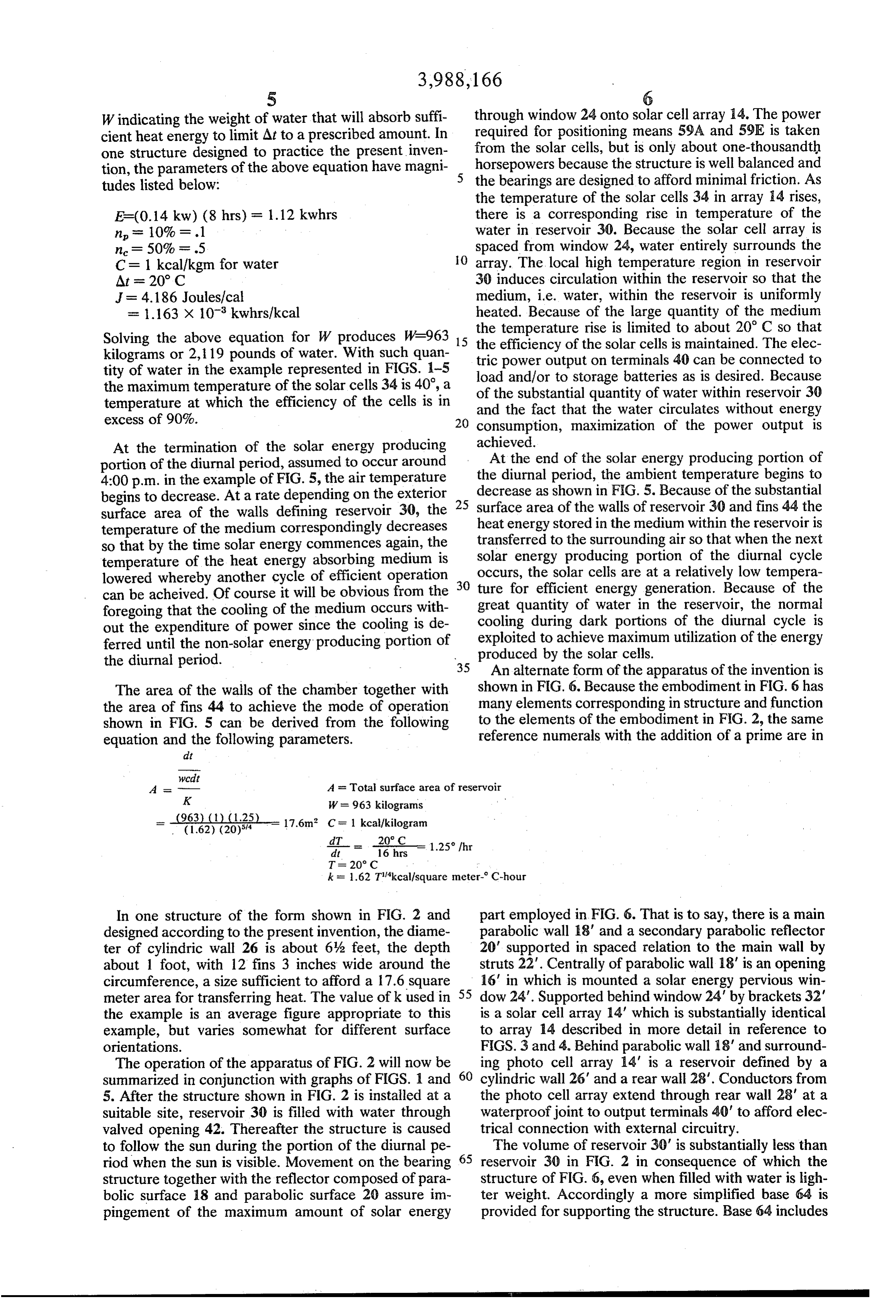
The cylindric wall terminates rearward of wall 18 producing portion of the diurnal period and to limit the where it is spanned by an impervious rear wall 28 so as 30 to form a watertight reservoir 30. The reservoir is temperature rise of solar cells 34. The heat energy bounded by parabolic wall 18, window 24, cylindric absorbed by the medium is transferred to the atmo wall 26 and rear wall 28. In the embodiment of FIG. 2, sphere at a more advantageous time i.e. during a por rear wall 28 is of parabolic shape; such shape improves tion of the diurnal period when no sunlight is present the balance or symmetry of the structure but is not 35 and consequently when the temperature of the environ critical. ment is lower. Referring to FIG. 5, wherein the time Solar array 14 is supported within chamber 30 by during a diurnal period is plotted on the abscissa and means of brackets 32; the solar cell array is supported the ambient temperature in degrees centigrade is plot in alignment with window 24 and spaced therefrom so 40 ted on the ordinate, curve 60 indicates the air tempera that the image of the solar rays emanating from secon ture variation in a typical environment. In the example dary reflector 20 is focused on the array. plotted in FIG. 5, the temperature varies from a high of Solar cell array 14 can be formed, for example, of about 30°C to a low of about 11°C. The temperature seven identical solar cells 34 which as shown in FIG. 3 of the medium in reservoir 30 is indicated by curve 62 are hexagonal shaped so as to afford closely spaced in FIG. 5 and is assumed to be Tabove the air temper mounting thereof. The solar cells are preferably about 45 ature. The difference between the maximum heat en 2 inches in maximum dimension to facilitate construc ergy absorbing medium temperature and the minimum tion of the same from a standard two inch boule of temperature is identified in FIG. 5 as At. Employing crystal material. The shape of the cells and their num known principles of thermodynamics the following ber is not critical, but will be determined from cost and formula is derived:
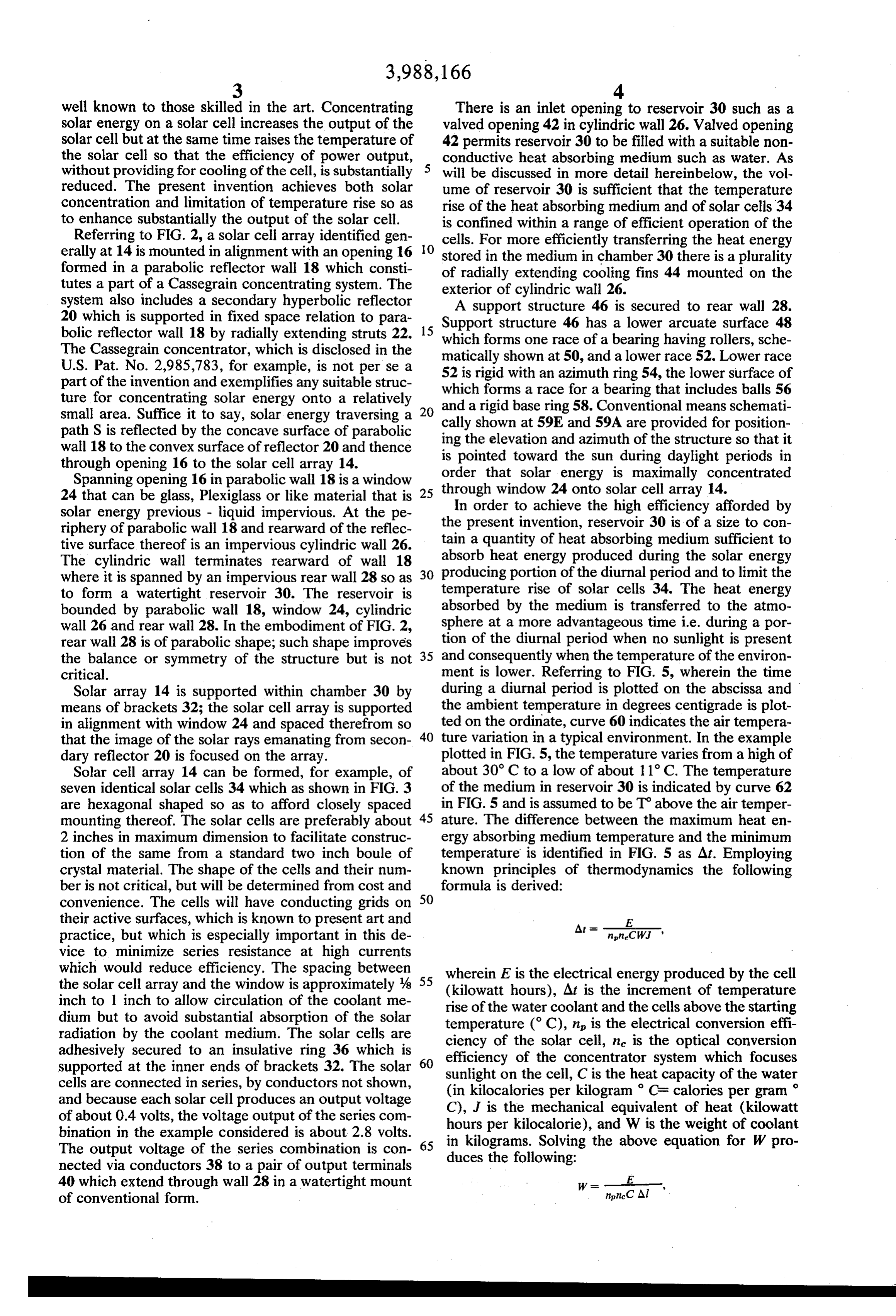
convenience. The cells will have conducting grids on 50 their active surfaces, which is known to present art and E practice, but which is especially important in this de At - W. , vice to minimize series resistance at high currents which would reduce efficiency. The spacing between the solar cell array and the window is approximately 4 55 wherein (kilowatt
E is the electrical energy produced by the cell hours), At is the increment of temperature inch to inch to allow circulation of the coolant me dium but to avoid substantial absorption of the solar rise of the water coolant and the cells above the starting radiation by the coolant medium. The solar cells are temperature (C), n is the electrical conversion effi adhesively secured to an insulative ring 36 which is ciency of the solar cell, n is the optical conversion supported at the inner ends of brackets 32. The solar 60 sunlight on the cell,concentrator efficiency of the
C is the heat system which focuses capacity of the water cells are connected in series, by conductors not shown, (in kilocalories per kilogram CF calories per gram and because each solar cell produces an output voltage C), J is the mechanical equivalent of heat (kilowatt of about 0.4 volts, the voltage output of the series com hours per kilocalorie), and W is the weight of coolant bination in the example considered is about 2.8 volts. in kilograms. Solving the above equation for W pro The output voltage of the series combination is con 65 nected via conductors 38 to a pair of output terminals duces the following:
40 which extend through wall 28 in a watertight mount E. of conventional form. non-C Al
Page 6
Windicating the weight of water that will absorb suffi through window 24 onto solar cell array 14. The power cient heatenergy to limit Atto a prescribed amount. In required for positioning means 59A and 59E is taken one structure designed to practice the present inven from the solar cells, but is only about one-thousandth tion, the parameters of the above equation have magni horsepowers because the structure is well balanced and tudes listed below: 5 the bearings are designed to afford minimal friction. As the temperature of the solar cells 34 in array i4 rises,
E=(0.14 kw) (8 hrs) = 1.12 kwhrs there is a corresponding rise in temperature of the n = 10% = .1 water in reservoir 30. Because the solar cell array is n = 50% = .5 spaced from window 24, water entirely surrounds the C = 1 kcal/kgm for water O array. The local high temperature region in reservoir At = 20°C 30 induces circulation within the reservoir so that the J = 4.186 Joules/cal medium, i.e. water, within the reservoir is uniformly = 1.163 x 10⁸ kwhrs/kcal heated. Because of the large quantity of the medium Solving the above equation for W produces W-963 is the the temperature rise is limited to about 20 C so that efficiency of the solar cells is maintained. The elec kilograms or 2,119 pounds of water. With such quan tric power output on terminals 40 can be connected to tity of water in the example represented in FIGS. 1-5 load and/or to storage batteries as is desired. Because the maximum temperature of the solar cells 34 is 40, a of the substantial quantity temperature at which the efficiency of the cells is in and the fact that the waterofcirculates water within reservoir 30 without energy excess of 90%. 2O consumption, maximization of the power output is At the termination of the solar energy producing achieved.
portion of the diurnal period, assumed to occur around theAtdiurnal the end of the solar energy producing portion of period, the ambient temperature begins to 4:00 p.m. in the example of FIG. 5, the air temperature begins to decrease. At a rate depending on the exterior 25 decrease as shown in F.G. 5. Because of the substantial surface area of the walls defining reservoir 30, the surface area of the walls of reservoir 30 and fins 44 the heatenergy stored in the medium within the reservoir is temperature of the medium correspondingly decreases transferred so that by the time solar energy commences again, the solar energyto producing the surrounding air so that when the next portion of the diurnal cycle temperature of the heat energy absorbing medium is occurs, the solar cells are at a relatively low tempera lowered whereby another cycle of efficient operation 30 ture for efficient energy generation. Because of the can beacheived. Of course it will be obvious from the foregoing that the cooling of the medium occurs with great quantity of water in the reservoir, the normal out the expenditure of power since the cooling is de cooling during dark portions of the diurnal cycle is ferred until the non-solar energy producing portion of exploited to achieve maximum utilization of the energy the diurnal period. produced by the solar cells.
35 An alternate form of the apparatus of the invention is
The area of the walls of the chamber together with shown in F.G. 6. Because the embodiment in FIG. 6 has the area of fins 44 to achieve the mode of operation many elements corresponding in structure and function shown in FIG. 5 can be derived from the following to the elements of the embodiment in FIG. 2, the same equation and the following parameters. reference numerals with the addition of a prime are in
vcdit
A - A = Total surface area of reservoir
In one structure of the form shown in FIG. 2 and part employed in FIG. 6. That is to say, there is a main designed according to the present invention, the diame parabolic wall 18' and a secondary parabolic reflector ter of cylindric wall 26 is about 6% feet, the depth 20' supported in spaced relation to the main wall by about 1 foot, with 12 fins 3 inches wide around the struts 22". Centrally of parabolic wall 18' is an opening circumference, a size sufficient to afford a 17.6 square 55 16' in which is mounted a solar energy pervious win meter area for transferring heat. The value of k used in dow 24'. Supported behind window 24' by brackets 32" the example is an average figure appropriate to this is a solar cell array 14 which is substantially identical example, but varies somewhat for different surface to array 14 described in more detail in reference to orientations. FIGS. 3 and 4. Behind parabolic wall 18' and surround The operation of the apparatus of FIG. 2 will now be 60 ing photo cell array 14" is a reservoir defined by a summarized in conjunction with graphs of FIGS. 1 and cylindric wall 26' and a rear wall 28'. Conductors from 5. After the structure shown in FIG. 2 is installed at a the photo cell array extend through rear wall 28' at a suitable site, reservoir 30 is filled with water through waterproof joint to output terminals 40' to afford elec valved opening 42. Thereafter the structure is caused trical connection with external circuitry. to follow the sun during the portion of the diurnal pe 65 The volume of reservoir 30' is substantially less than riod when the sun is visible. Movement on the bearing reservoir 30 in FIG. 2 in consequence of which the structure together with the reflector composed of para structure of FIG. 6, even when filled with water is ligh bolic surface 18 and parabolic surface 20 assure im ter weight. Accordingly a more simplified base 64 is pingement of the maximum amount of solar energy provided for supporting the structure. Base 64 includes
Page 7
suitable means for maintaining the concentrator from a local source is supplied to the system and opera pointed at the sun during solar energy producing por tion proceeds as described above. tions of the diurnal period. Communicating with reser To underscore the important advance represented by voir 30' is an outlet hose 66 and an inlet hose 68. The the present invention it is pointed out that, based on hoses communicate with a storage chamber 70, which costs applicable at the time offiling the application, for has fins 72 on the exterior thereof, and in order to a plurality of systems that will supply 1 kilowatt contin distribute the absorbed heat energy throughout the uous is about $2,500 to $3,000; this amount is approxi quantity of water contained in reservoir 30' and cham mately equal to the capitalized cost that public utilities ber 70, there is a low power circulator 73. The com require to deliver energy to a home. As a basis of com bined volume of reservoir 30' and chamber 70 is the 10 parison with current art in photovoltaic power supplies, same as the volume of reservoir 30 described herein the previously cited Ralph reference quotes $20 per above. Consequently, there is a sufficient quantity of watt or more than $60,000 to supply 1 kilowatt contin heat energy absorbing medium to absorb the heat gen uous by the method proposed therein. In addition to erated during the solar energy producing portion of the the favorable cost comparisons with conventional diurnal period to limit the temperature rise of solar 15 sources of energy, the present invention produces no cells. Circulator 73, because it only circulates the water pollutants and avoids consumption of limited natural to achieve temperature equilibrium within reservoir resources. Although several embodiments have been 30' and chamber 70 consumes very little power as shown and described, it will be obvious that other adap compared with the power required to drive the high speed pump employed in the Beckman publication tations ing from and modifications can be made without depart the true spirit and scope of the invention.
cited hereinabove. Moreover, because the weight of What is claimed is:
the water in reservoir 30' is less than the weight of the 1. Apparatus for generating electrical energy in a water in reservoir 30, the positioning apparatus in base terrestrial 64 of the embodiment of FIG. 6 consumes less power 25 voltaic cell,environment means for comprising at least one photo defining a liquid impervious so that the system of FIG. 6 affords substantially the closed chamber for containing said cell, said chamber same efficiency as the system of FIG. 2. defining means including a parabolic wall, said para The operation of the embodiment of FIG. 6 is sub bolic. wall defining a solar energy pervious window stantially identical to that referred to above. As the therein, means for supporting said cell within said structure tracks the sun, energy is produced by the 30 chamber adjacent to and spaced from said window by solar cells and the temperature rise of the solar cells is distance, said parabolic wall having a reflective cona limited to about 20 C because of the heat energy ab cave surface, means including said reflective concave sorbed in the water disposed in reservoir 30' and cham surface ber 70. Circulator 73 slowly moves the water through through for said concentrating solar energy onto said cell window, a quantity of nonconductive liq the system so that the heat energy absorbed in the 35 uid means substantially filling said chamber and sur relatively warm water in reservoir 30' is distributed to rounding said cell for absorbing heat energy therefrom, the water in chamber 70. After termination of the por said quantity of said liquid energy absorbing means tion of the diurnal period during which solar energy is being sufficiently large to absorb and store heat energy produced, the absorbed heat is transferred to the rela tively cooler atmosphere, fins 72 contributing to such 40 from said photovoltaic cell to limit the temperature rise cooling. In addition, the exterior surface areas of reser of said cell during the solar energy producing portion of a diurnal period, said distance being large enough to voir 30' contribute to heat energy transfer.
Thus it will be seen that the present invention pro allow liquid circulation between said cell and said win vides an apparatus for producing electric power which dow and small enough to avoid substantial absorption is efficient and inexpensive in that it employs a few of solar energy by the liquid means, the chamber de solar cells with concentrated energy directed thereon 45 fined by said chamber defining means having sufficient and which consumes little or no power for limiting the external surface area to afford transfer of heat from temperature rise of the cells. Because the method is said liquid to the environment during the remainder of operative throughout the entire diurnal period, the the diurnal period.
normal atmosphere cooling during nightime is ex 2. Apparatus according to claim 1 including first and ploited to optimize energy generation. Moreover, be 50 second vessels, said first vessel being integral with said cause the apparatus is designed to employ water as the parabolic wall, said second vessel being remote from heat energy absorbing medium, the apparatus is rela said parabolic wall, and means for establishing fluid tively light in weight during transport and installation at communication between k said vessels.
a site. When installation has been completed, water 55
Provenance
- Collection
- Cited prior art
- Original PDF
- patentimages.storage.googleapis.com →
- Filed
- 1975-01-07
- Pages
- 7
- Method
- pdftotext (the PDF's own text layer) + pdftoppm 300dpi page scans
- Source
- Google Patents bibliographic record
- Granted
- 1976-10-26
- Inventors
- Benjamin H. Beam; Beam Engineering Inc
- Transcribed from
- patentimages.storage.googleapis.com →