patent · US4822469
Electrical power supply for an electrolytic gas generator
18 April 1989
Page 1 — bibliographic record
United States Patent (19 11) Patent Number: 4,822,469 Shimomura et al. (45) Date of Patent: Apr. 18, 1989 54 ELECTRICAL POWER SUPPLY FOR AN erator includes an input network provided with a first ELECTROLYTIC GAS GENERATOR rectifying-flattening circuit for generating a DC voltage 75 Inventors: Mitsuzo Shimomura; Yoshiro Torii, from an AC power source voltage input thereto and an both of Minami, Japan output network provided with a switching circuit for generating a pulse voltage having a predetermined fre 73) Assignee: Stec Inc., Kyoto, Japan quency from the DC voltage supplied from the input (21) Appl. No.: 155,534 network and a second rectifying-flattening circuit for 22 Filed: Feb. 12, 1988 transforming the pulse voltage into the DC voltage and for supplying this DC voltage to an electrode of the 30 Foreign Application Priority Data electrolytic cell. The power supply further includes a Mar. 8, 1987 JP Japan ............................. 62-33736(U) voltage-adjusting circuit for generating an error signal corresponding to the difference between a feedback 51) Int. Cl." ......................... C25B 15/02; C25B 9/04 signal for any one of a signal corresponding to the out 52 U.S. Cl. ..................................... 204/230; 204/278 put voltage from the output network and a signal corre 58) Field of Search ............... 204/230, 278, 270, 129, sponding to a detected pressure of the gas generated
within the electrolytic cell and a standard signal corre (56) References Cited sponding to a design pressure of the gas generated so as
the pressure of the gas generated at a predetermined 3,336,215 8/1967 Hagen ................................. 204/230 design value and further includes a frequency-fixed 3,448,035 6/1969 Serfass ......... ... 204/278 pulse-width modulator for generating a pulse-signal 3,485,742 12/1969 Emich et al. ... 204/230 3,489,670 12/1969 Maget...... ... 204/129 having a predetermined frequency modulated to a 3,755,128 8/1973 Herwig ........... ... 204/230 pulse-width corresponding to the error signal and a 3,870,616 3/1975 Dempsey et al. ... 204/230 driver circuit for generating a drive pulse for control 4,078,985 3/1978 Takeuchi............. ... 204/230 ling the switching of the switching circuit in the output 4,113,601 9/1978 Spirig .................................. 204/230 network in accordance with the modulated pulse signal Primary Examiner-Donald R. Valentine from the modulator.
Attorney, Agent, or Firm-Wenderoth, Lind & Ponack
An electrical power supply for an electrolytic gas gen 1 Claim, 6 Drawing Sheets
ELECTRICAL UNIT
- CONTROL
DISPLAY
Page 2
Drawing sheet — no readable text.
Page 3
Drawing sheet — no readable text.
Page 4
Drawing sheet — no readable text.
Page 5
Drawing sheet — no readable text.
Page 6
Drawing sheet — no readable text.
Page 7
Drawing sheet — no readable text.
Page 8
provided with an electrode 05 (cathode) for electrolyz
ELECTRICAL POWER SUPPLY FOR AN ing water to evolve the desired gas, which is hydrogen ELECTROLYTIC GAS GENERATOR gas, and an electrode (anode) 06 for evolving oxygen gas to be discharged therein so that an electrolytic
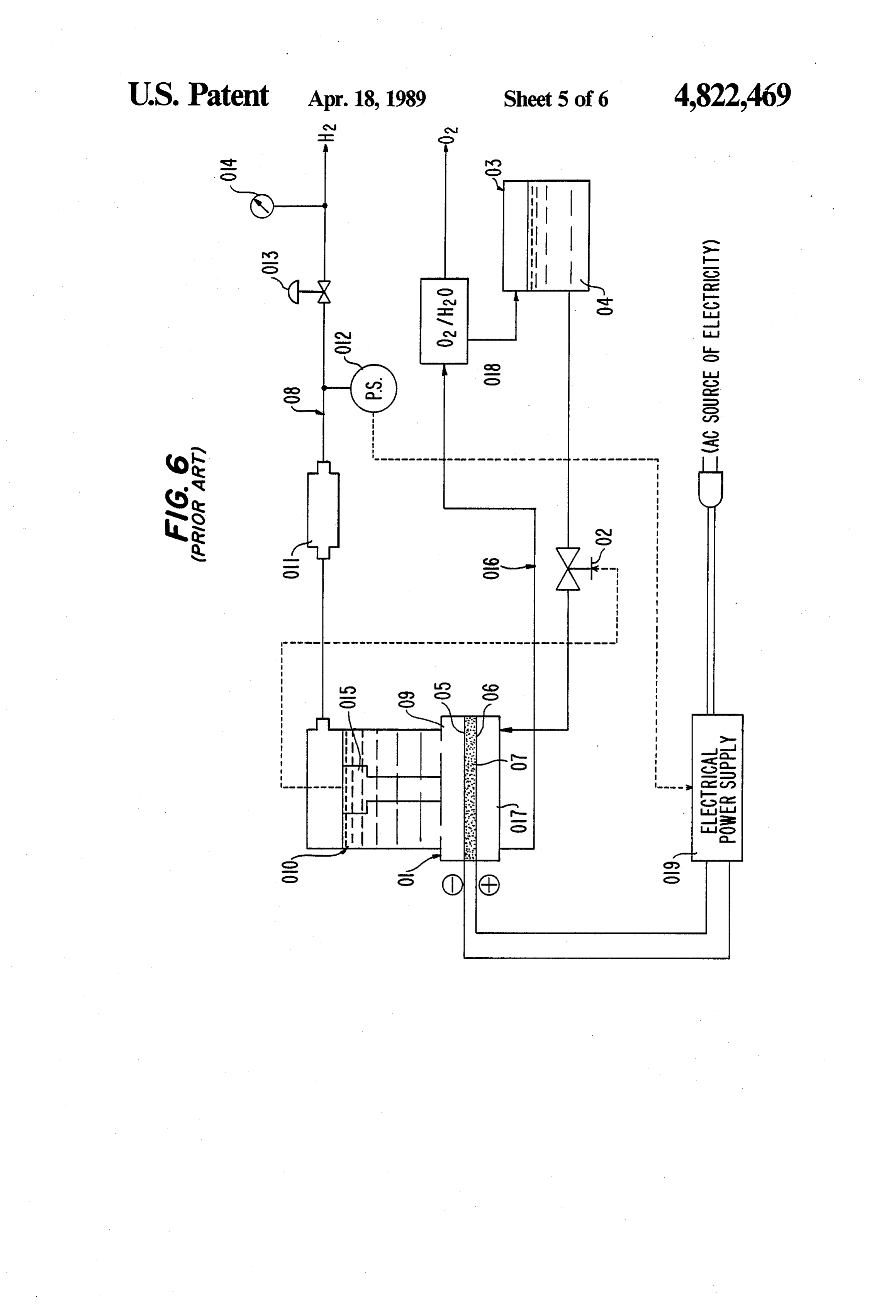
BACKGROUND OF THE INVENTION 5 membrane 07 may be held between the electrode 05 and The present invention relates to an electrolytic gas the electrode 06. In addition, reference numeral 08 des generator (for generating, for example-hydrogen gas) ignates a hydrogen gas passage connected to the elec which is frequency used as a source of a carrier gas in trolytic cell 01 for taking out hydrogen gas evolved in gas chromatography, a source of fuel gas for an analy O the electrolytic cell 01 and comprising a hydrogen gas zer using a flame ion detector (FID) or a flame photo separating trap 010 directly communicating with a liq metric detector (FPD) and the like, a source of gas for uid chamber 09 of the cathode 05 side in the electrolytic use in physical and chemical laboratories and the like; cell 01, a humidity-removing cylinder 011, a pressure that is to say, a supply source of a relative small and switch 012 which turns ON when the gas pressure in the constant quantity of gas. More particularly, the present passage reaches at least a predetermined value, a pres invention relates to an improve cell voltage controller 15 sure regulator 03, and a pressure gauge 014 arranged in in an electrolytic gas generator comprising: this order. Reference numeral 015 designates a water an electrolytic cell for passing a predetermined elec level sensor for generating a signal when the water trolyte therethrough and provided with an electrode for within the hydrogen gas-separating trap 010 reaches at electrolyzing the electrolyte so as to generate a desired least a predetermined water level so as to close the gas therein and a gas passage communicatingly con 20 electromagnetic on-off valve 02, thereby stopping the nected therewith for taking out the generated desired supply of water from the electrolyte tank 03. In addi gas and tion, reference number 016 designates an oxygen gas an electrical power supply for supplying the elec discharging passage communicatingly connected to a trode in the electrolytic cell with electrical power for liquid chamber 017 of the anode 06 side of the electro use in the electrolysis. 25 lytic cell 01 for taking out oxygen gas evolved in the
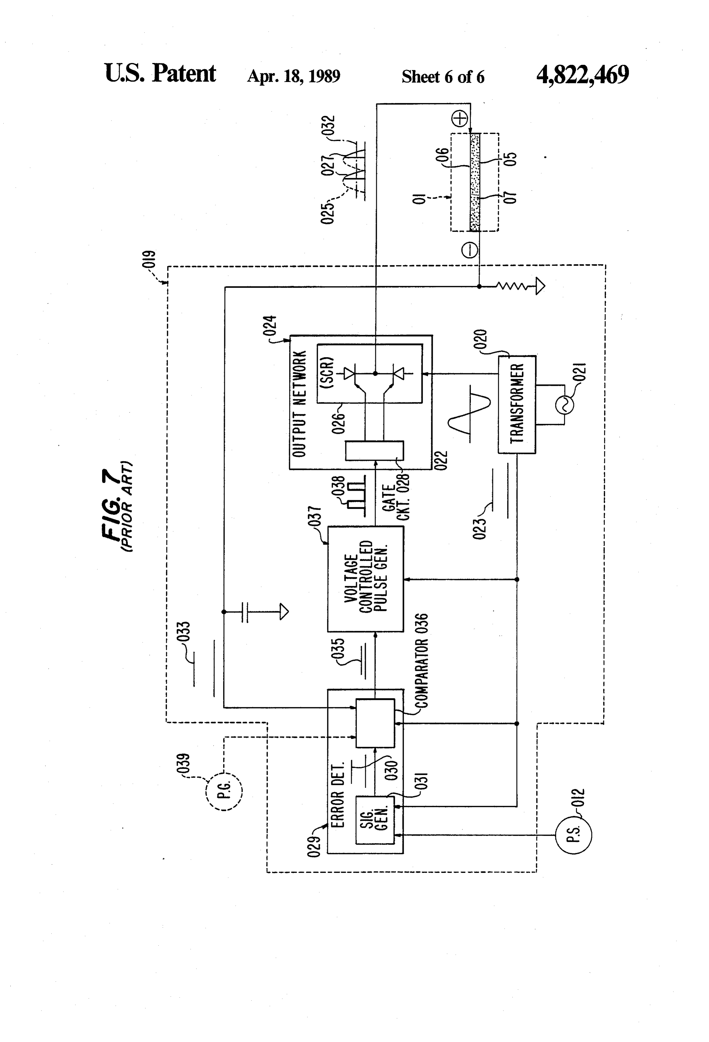
The basic construction of an electrolytic gas genera electrolytic cell 01 and provided with an oxygen gas tor of this type is shown in U.S. Pat. Nos. 3,489,670 and separating trap 018 in the middle thereof. Water sepa 3,448,035, for example. rated from the oxygen gas in the oxygen gas-separating In addition, a basic voltage-controller construction, trap such as providing an electrical power-controller, which 30 ence 018 is returned to the electrolyte tank 03. Refer numeral 019 designates an electrical power supply carries out a feedback control for a supply current on for supplying the electrodes 05 and 06 in the electrolytic the basis of a signal corresponding to the supply current cell 01 with a current for use in the electrolysis and itself so that the electrical power (in this case, the cur having an electrical power rent has an important meaning since electrolysis is used) rying out a feedback controlcontroller for the function for car supply current on for use in the electrolysis and supplied to the electrode 35 of the electrolytic cell may be held at a predetermined the basis of the supply current itself so that the supply current to the electrodes 05 and 0.6 may be held at a design value, or providing an electrical power-con predetermined troller, which carries out a feedback control for the design value and having an emergency supply current on the basis of a signal corresponding to controller function for lowering or stopping the supply a pressure detected by a gas pressure sensor provided in ing of electrical power to the electrodes 05 and 06 when the gas passage for taking out the generated gas so that the gas pressure within the hydrogen gas passage 08 the pressure of the gas generated by the electrolytic cell reaches at least a predetermined value so as to turn ON may be held at a predetermined design value, is shown the pressure switch 012, as described below in detail in U.S. Pat. No. 3,485,742, for example. with reference to the block diagram of FIG. 7. However, with an electrolytic gas generator of this 45 The electrical power supply 019 as shown in FIG. 7 kind, since it is used in specialized fields as a supply comprises a power source transformer 020 for generat source of a relatively small and constant quantity of gas, ing a transformed AC 022, which becomes the basis of it must be capable of stably controlling its output of gas. the electrical power supplied to the electrodes 05 and 06 Accordingly, an important problem is how the control in the electrolytic cell 01 from an AC power source of the electrical power is precisely and stably carried 50 voltage 021 input thereto, and a DC control voltage 023 out whether the feedback control for the electrical to be supplied to each of desired circuits for use in the current supplied to the electrode in the above described control which will be discussed later. electrolytic cell is carried out on the basis of a signal In addition, reference numeral 024 designates an out corresponding to the supply current itself or is carried put network for generating the supply current for the out on the basis of a signal corresponding to the de 55 electrodes 05 and 06 in the electrolytic cell 01 provided tected pressure of the generated gas. Accordingly, vari with an AC solid state switching device (hereinafter ous kinds of devices have been tried in order to solve referred to as an SCR) 026 for converting the trans such a problem. formed AC voltage 022 supplied from the power source A recent technique, which is noteworthy in this re transformer 020 into a pulsating current 025 an a gate spect, has been proposed in U.S. Pat. No. 3,870,616. 60 circuit 028 adapted to operate so as to output only a part That is, a conventional electrolytic (hydrogen) gas (a partially switched-on divided pulsating current 027) generator according to U.S. Pat. No. 3,870,616 has a of the pulsating current 025 generated by the SCR 026. construction as shown in FIGS. 6 and 7. In addition, reference numeral 029 designates an er Referring now to the block diagram illustrated in ror-detecting network provided with a basic signal FIG. 6, reference numeral 01 designates an electrolytic 65 generating circuit 031 for generating a basic signal 030 cell for passing a predetermined electrolyte 04 (in this corresponding to the predetermined design value from example, water: H2O) supplied from an electrolytic the DC voltage 023 supplied from the power source tank 03 through an electromagnetic on-off valve 02 and transformer 020 and a comparator circuit 036 for gener
Page 9
ating an error signal 035 corresponding to a difference (b) Since a peak current of the pulsating current 025 between the basic signal 030 and a feedback signal 033 is higher (at least twice) in comparison with the average corresponding to an average current 032 output from current 032 which is a substantial current supplied to the output network 024 and flowing the electrolytic cell the electrodes 05 and 06, various electrical constituent 01. Reference numeral 037 designates a voltage con elements must have higher anti-current characteristics, trolled variable repetition frequency pulse generator for whereby the electrical power supply 019 is apt to be supplying a trigger pulse 038 to the gate circuit 028 in large-sized and expensive as a whole coupled with the the output network 024 and adapted to output a trigger disadvantage (a);
pulse 038 having a frequency corresponding to a magni (c) Since the construction, in which the divided pull tude of the error signal 035 supplied from the error 10 sating current 027 is supplied to the electrodes 05 and 06 detecting network 029. in the electrolytic cell 01, is adopted, the voltage-sup In addition, the basic signal-generating circuit 031 in plying state is apt to be fundamentally unstable; the error-detecting network 029 receives a detected (d) Since a control mode, in which the originally signal from the pressure switch 012 provided in the nonlinear pulsating current 025 is gated-on by a trigger hydrogen gas passage 08 as shown in FIG. 6 and adopts 15 pulse to obtain the divided pulsating current 027, is a safety-controlling construction such that the basic adopted, a linear feedback control is not carried out, signal generated by the basic signal-generating circuit thereby being apt to cause a hunting phenomenon; and 031 is significantly lower than the original design value (e) Since the construction, in which the divided pull in the case where the gas pressure within the passage 08 sating current 027 having a peak current higher than the reaches at least the predetermined value and the ON 20 average current 032 is supplied to the electrodes 05 and signal from the pressure switch 012 is supplied to the 06 in the electrolytic cell 01, is adopted, the heat loss basic signal-generating circuit 031, thereby lowering power of the electrolytic cell 01 becomes compara the supply current to the electrodes 05 and 06 in the tively large, thereby increasing the loss of electrical electrolytic cell 01. power and significantly reducing the useful lifetime of In addition, as described above, U.S. Pat. No. 25 the electrolytic cell 01 on account of a bad influence 3,870,616 also discloses that the feedback control for the due to the consumption of the electrolytic membrane 07 supply current to the electrodes 05 and 06 can be car and the like.
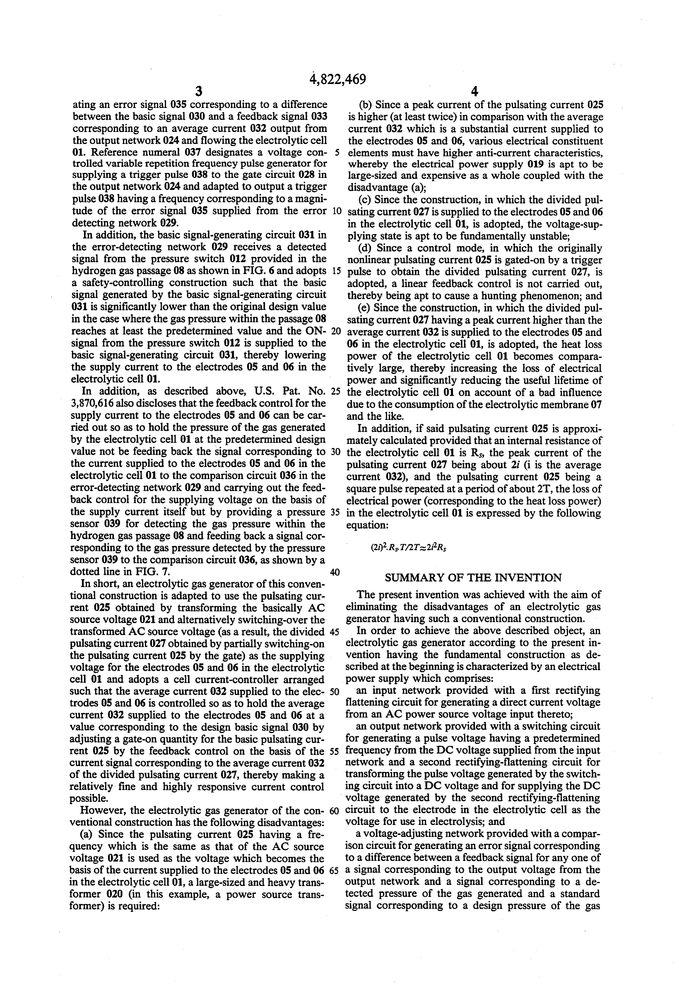
ried out so as to hold the pressure of the gas generated In addition, if said pulsating current 025 is approxi by the electrolytic cell 01 at the predetermined design mately calculated provided that an internal resistance of value not be feeding back the signal corresponding to 30 the electrolytic cell 01 is Rs, the peak current of the the current supplied to the electrodes 05 and 06 in the pulsating current 027 being about 2i (i is the average electrolytic cell 01 to the comparison circuit 036 in the current 032), and the pulsating current 025 being a error-detecting network 029 and carrying out the feed square pulse repeated at a period of about 2T, the loss of back control for the supplying voltage on the basis of electrical power (corresponding to the heat loss power) the supply current itself but by providing a pressure 35 in the electrolytic cell 01 is expressed by the following sensor 039 for detecting the gas pressure within the equation:
hydrogen gas passage 08 and feeding back a signal cor responding to the gas pressure detected by the pressure sensor 039 to the comparison circuit 036, as shown by a dotted line in FIG. 7. SUMMARY OF THE INVENTION In short, an electrolytic gas generator of this conven tional construction is adapted to use the pulsating cur The present invention was achieved with the aim of rent 025 obtained by transforming the basically AC eliminating the disadvantages of an electrolytic gas source voltage 021 and alternatively switching-over the generator having such a conventional construction. transformed AC source voltage (as a result, the divided 45 In order to achieve the above described object, an pulsating current 027 obtained by partially switching-on electrolytic gas generator according to the present in the pulsating current 025 by the gate) as the supplying vention having the fundamental construction as de voltage for the electrodes 05 and 06 in the electrolytic scribed at the beginning is characterized by an electrical cell 01 and adopts a cell current-controller arranged power supply which comprises:
such that the average current 032 supplied to the elec 50 an input network provided with a first rectifying trodes 05 and 06 is controlled so as to hold the average flattening circuit for generating a direct current voltage current 032 supplied to the electrodes 05 and 06 at a from an AC power source voltage input thereto; value corresponding to the design basic signal 030 by an output network provided with a switching circuit adjusting a gate-on quantity for the basic pulsating cur for generating a pulse voltage having a predetermined rent 025 by the feedback control on the basis of the 55 frequency from the DC voltage supplied from the input current signal corresponding to the average current 032 network and a second rectifying-flattening circuit for of the divided pulsating current 027, thereby making a transforming the pulse voltage generated by the switch relatively fine and highly responsive current control ing circuit into a DC voltage and for supplying the DC possible. voltage generated by the second rectifying-flattening However, the electrolytic gas generator of the con circuit to the electrode in the electrolytic cell as the ventional construction has the following disadvantages: voltage for use in electrolysis; and (a) Since the pulsating current 025 having a fre a voltage-adjusting network provided with a compar quency which is the same as that of the AC source ison circuit for generating an error signal corresponding voltage 021 is used as the voltage which becomes the to a difference between a feedback signal for any one of basis of the current supplied to the electrodes 05 and 06 65 a signal corresponding to the output voltage from the in the electrolytic cell 01, a large-sized and heavy trans output network and a signal corresponding to a de former 020 (in this example, a power source trans tected pressure of the gas generated and a standard former) is required: signal corresponding to a design pressure of the gas
Page 10
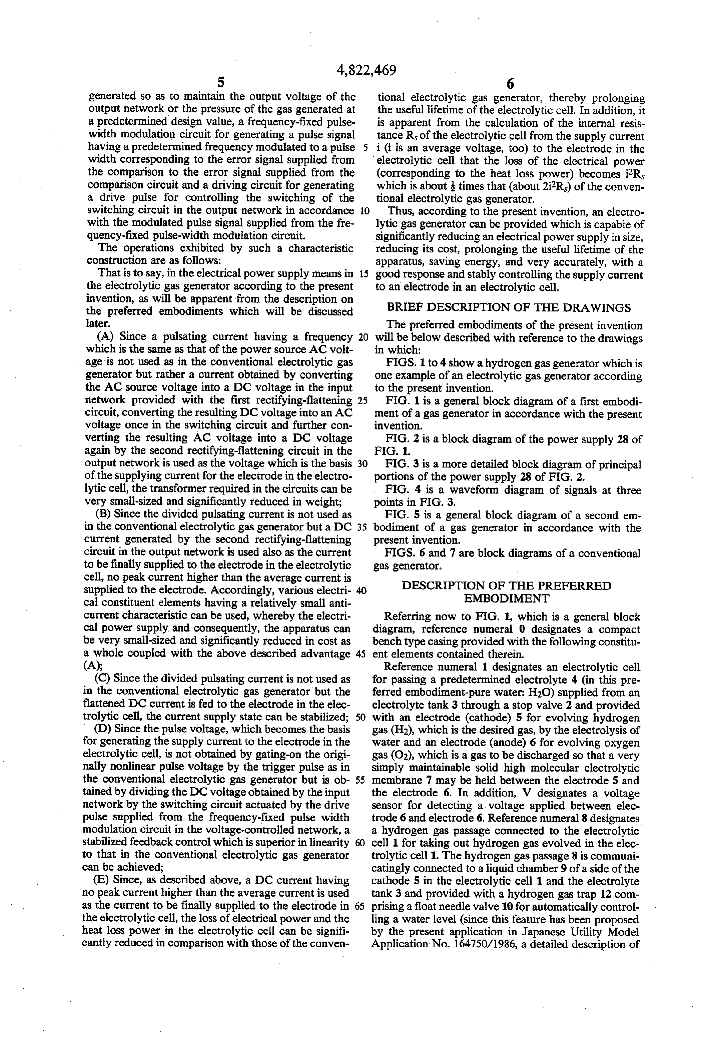
generated so as to maintain the output voltage of the tional electrolytic gas generator, thereby prolonging output network or the pressure of the gas generated at the useful lifetime of the electrolytic cell. In addition, it a predetermined design value, a frequency-fixed pulse is apparent from the calculation of the internal resis width modulation circuit for generating a pulse signal tance Rs of the electrolytic cell from the supply current having a predetermined frequency modulated to a pulse i (i is an average voltage, too) to the electrode in the width corresponding to the error signal supplied from electrolytic cell that the loss of the electrical power the comparison to the error signal supplied from the (corresponding to the heat loss power) becomes i2Rs comparison circuit and a driving circuit for generating which is about times that (about 2iR) of the conven a drive pulse for controlling the switching of the tional electrolytic gas generator.
switching circuit in the output network in accordance O Thus, according to the present invention, an electro with the modulated pulse signal supplied from the fre lytic gas generator can be provided which is capable of quency-fixed pulse-width modulation circuit. significantly reducing an electrical power supply in size, The operations exhibited by such a characteristic reducing its cost, prolonging the useful lifetime of the construction are as follows: apparatus, saving energy, and very accurately, with a That is to say, in the electrical power supply means in 15 good response and stably controlling the supply current the electrolytic gas generator according to the present to an electrode in an electrolytic cell. invention, as will be apparent from the description on BRIEF DESCRIPTION OF THE DRAWINGS the preferred embodiments which will be discussed later. The preferred embodiments of the present invention (A) Since a pulsating current having a frequency 20 will be below described with reference to the drawings which is the same as that of the power source AC volt in which:
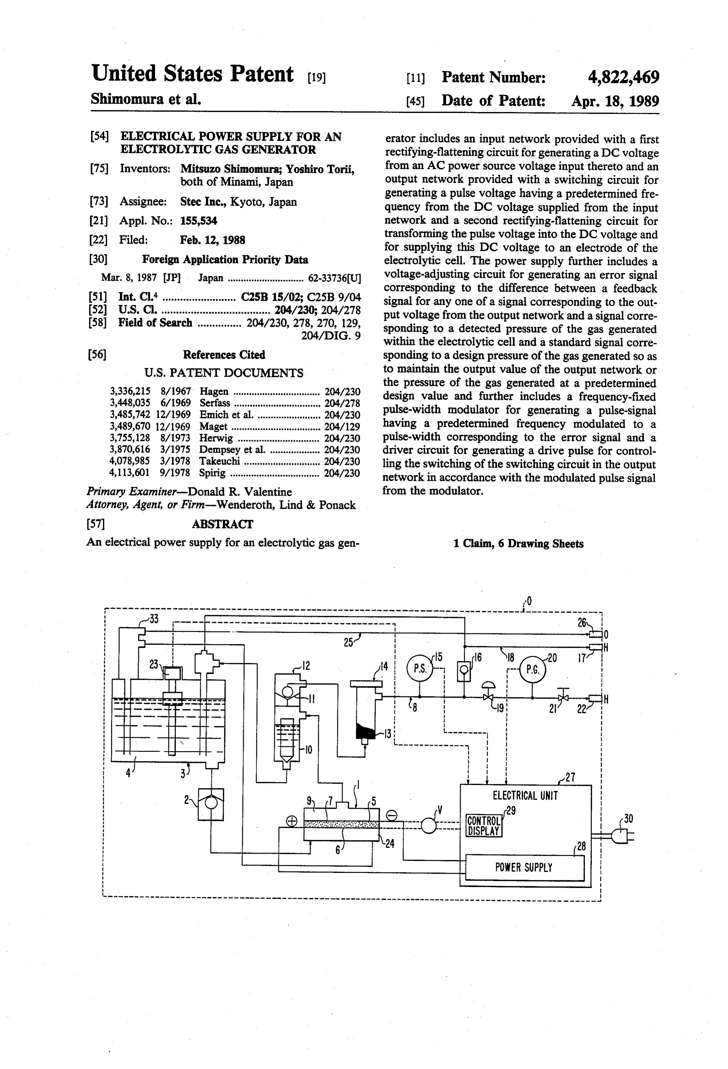
age is not used as in the conventional electrolytic gas FIGS. 1 to 4 show a hydrogen gas generator which is generator but rather a current obtained by converting one example of an electrolytic gas generator according the AC source voltage into a DC voltage in the input to the present invention.
network provided with the first rectifying-flattening 25 FIG. 1 is a general block diagram of a first embodi circuit, converting the resulting DC voltage into an AC ment of a gas generator in accordance with the present voltage once in the switching circuit and further con invention.
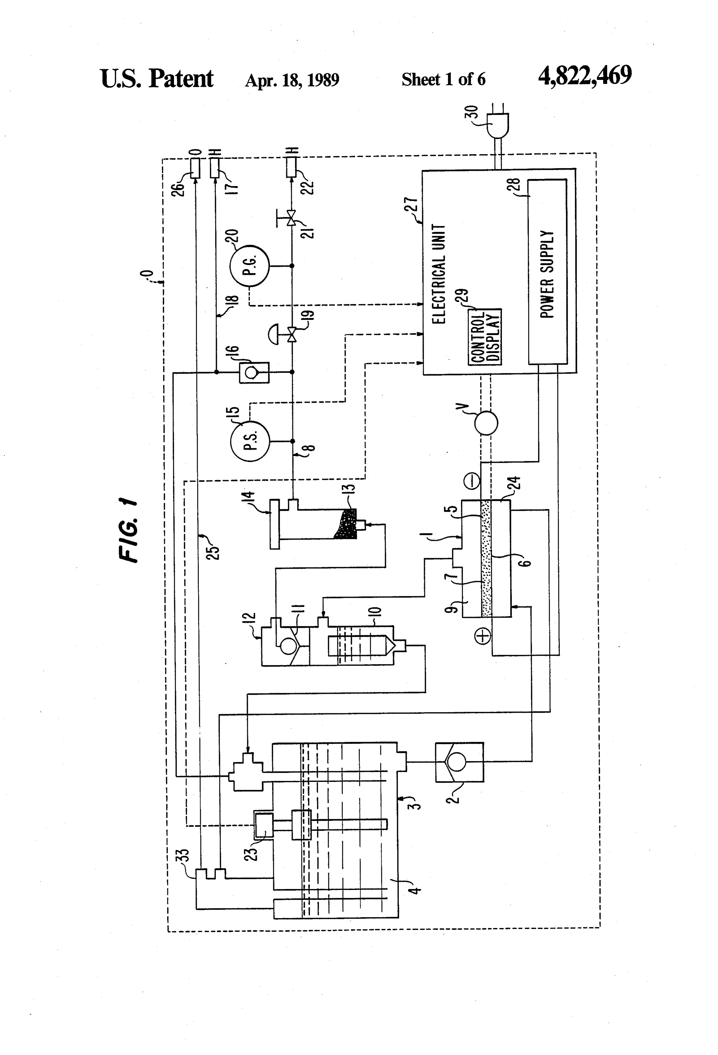
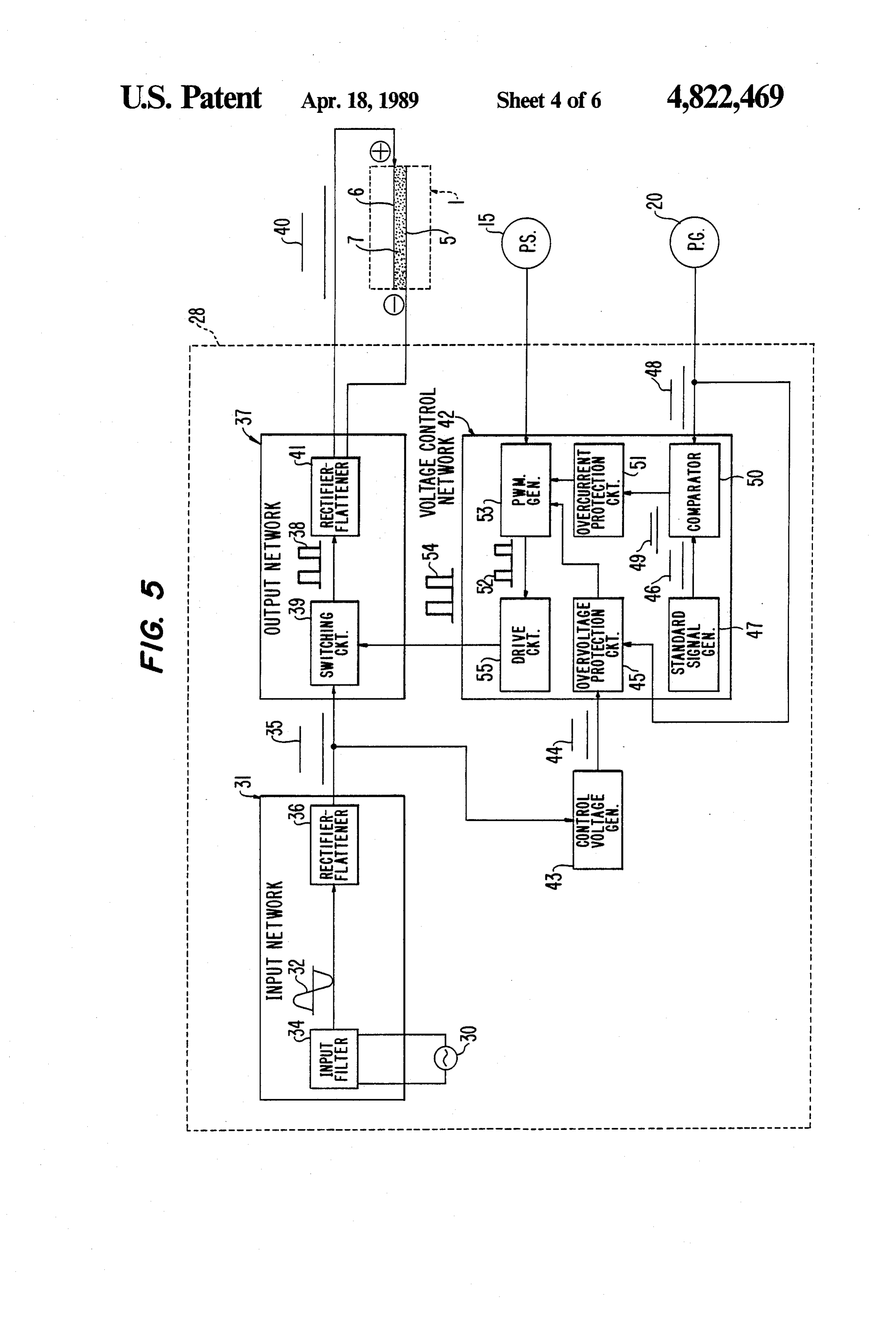
verting the resulting AC voltage into a DC voltage FIG. 2 is a block diagram of the power supply 28 of again by the second rectifying-flattening circuit in the FIG. 1.
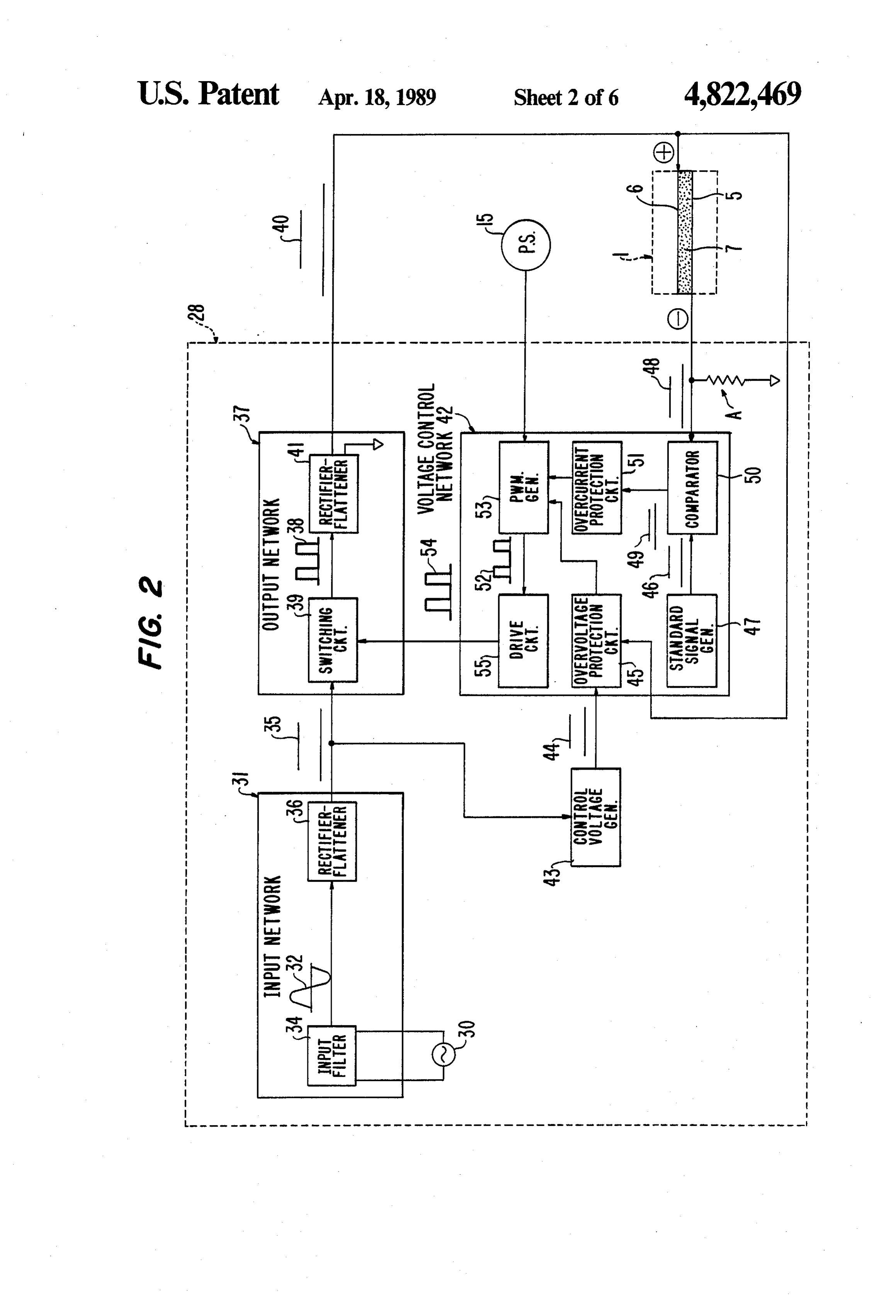
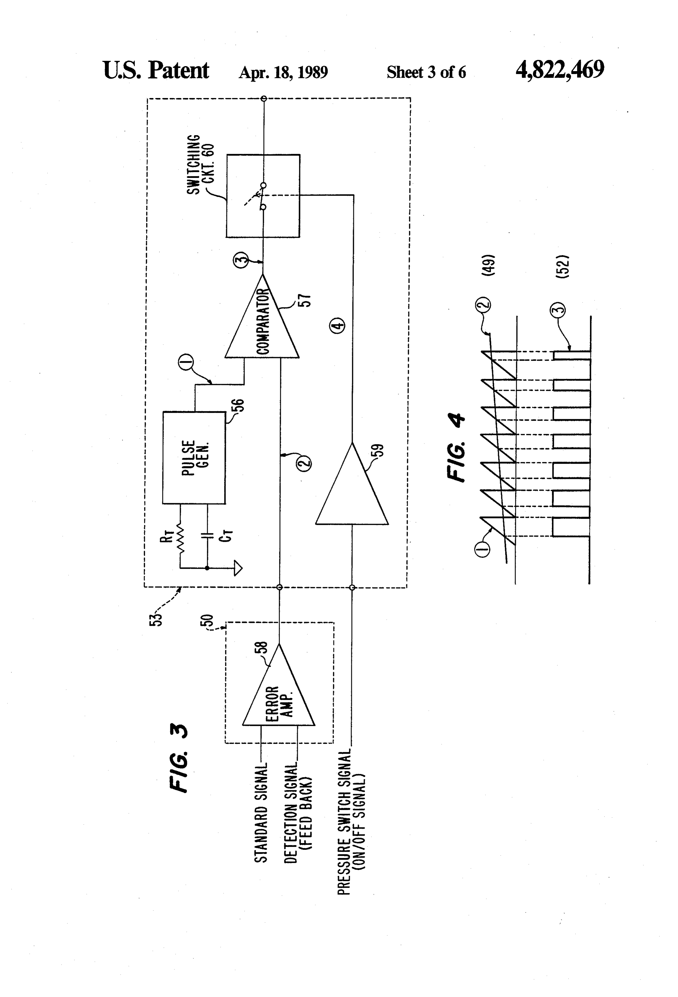
output network is used as the voltage which is the basis 30 FIG. 3 is a more detailed block diagram of principal of the supplying current for the electrode in the electro portions of the power supply 28 of FIG. 2. lytic cell, the transformer required in the circuits can be FIG. 4 is a waveform diagram of signals at three very small-sized and significantly reduced in weight; points in FIG. 3.
(B) Since the divided pulsating current is not used as FIG. 5 is a general block diagram of a second em in the conventional electrolytic gas generator but a DC 35 bodiment of a gas generator in accordance with the current generated by the second rectifying-flattening present invention.
circuit in the output network is used also as the current FIGS. 6 and 7 are block diagrams of a conventional to be finally supplied to the electrode in the electrolytic gas generator.
cell, no peak current higher than the average current is DESCRIPTION OF THE PREFERRED supplied to the electrode. Accordingly, various electri EMBODIMENT cal constituent elements having a relatively small anti current characteristic can be used, whereby the electri Referring now to FIG. 1, which is a general block cal power supply and consequently, the apparatus can diagram, reference numeral 0 designates a compact be very small-sized and significantly reduced in cost as bench type casing provided with the following constitu a whole coupled with the above described advantage 45 ent elements contained therein.
(A); Reference numeral 1 designates an electrolytic cell. (C) Since the divided pulsating current is not used as for passing a predetermined electrolyte 4 (in this pre in the conventional electrolytic gas generator but the ferred embodiment-pure water: H2O) supplied from an flattened DC current is fed to the electrode in the elec electrolyte tank 3 through a stop valve 2 and provided trolytic cell, the current supply state can be stabilized; 50 with an electrode (cathode) 5 for evolving hydrogen (D) Since the pulse voltage, which becomes the basis gas (H2), which is the desired gas, by the electrolysis of for generating the supply current to the electrode in the water and an electrode (anode) 6 for evolving oxygen electrolytic cell, is not obtained by gating-on the origi gas (O2), which is a gas to be discharged so that a very nally nonlinear pulse voltage by the trigger pulse as in simply maintainable solid high molecular electrolytic the conventional electrolytic gas generator but is ob 55 membrane 7 may be held between the electrode 5 and tained by dividing the DC voltage obtained by the input the electrode 6. In addition, V designates a voltage network by the switching circuit actuated by the drive sensor for detecting a voltage applied between elec pulse supplied from the frequency-fixed pulse width trode 6 and electrode 6. Reference numeral 8 designates modulation circuit in the voltage-controlled network, a a hydrogen gas passage connected to the electrolytic stabilized feedback control which is superior in linearity cell 1 for taking out hydrogen gas evolved in the elec to that in the conventional electrolytic gas generator trolytic cell 1. The hydrogen gas passage 8 is communi can be achieved; catingly connected to a liquid chamber 9 of a side of the (E) Since, as described above, a DC current having cathode 5 in the electrolytic cell 1 and the electrolyte no peak current higher than the average current is used tank 3 and provided with a hydrogen gas trap 12 con as the current to be finally supplied to the electrode in 65 prising afloat needle valve 10 for automatically control the electrolytic cell, the loss of electrical power and the ling a water level (since this feature has been proposed heat loss power in the electrolytic cell can be signifi by the present application in Japanese Utility Model cantly reduced in comparison with those of the conven Application No. 164750/1986, a detailed description of
Page 11
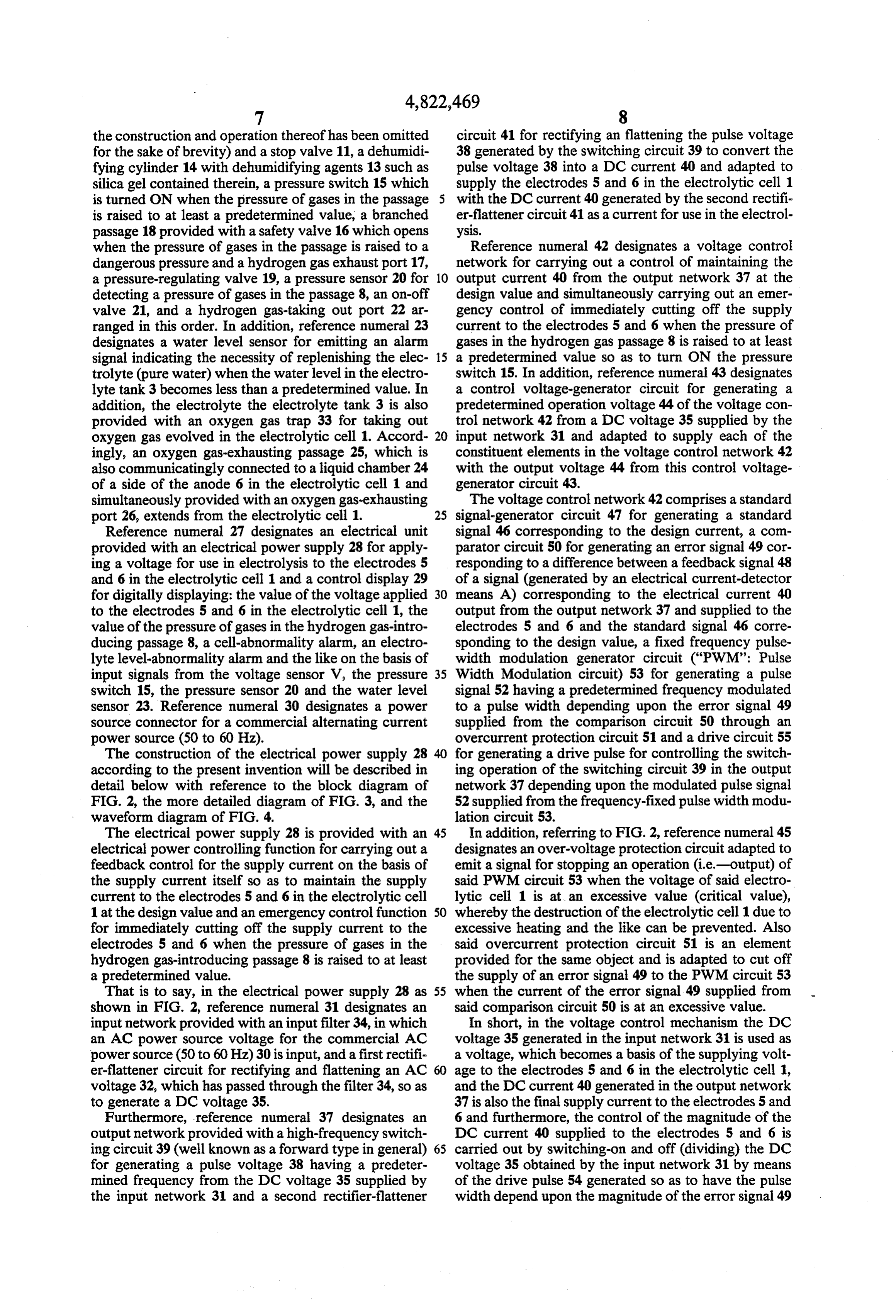
the construction and operation thereof has been omitted circuit 41 for rectifying an flattening the pulse voltage for the sake of brevity) and a stop valve 11, a dehumidi 38 generated by the switching circuit 39 to convert the fying cylinder 14 with dehumidifying agents 13 such as pulse voltage 38 into a DC current 40 and adapted to silica gel contained therein, a pressure switch 15 which supply the electrodes 5 and 6 in the electrolytic cell 1 is turned ON when the pressure of gases in the passage 5 with the DC current 40 generated by the second rectifi is raised to at least a predetermined value, a branched er-flattener circuit 41 as a current for use in the electrol passage 18 provided with a safety valve 16 which opens ySIS.
when the pressure of gases in the passage is raised to a Reference numeral 42 designates a voltage control dangerous pressure and a hydrogen gas exhaust port 17, network for carrying out a control of maintaining the a pressure-regulating valve 19, a pressure sensor 20 for 10 output current 40 from the output network 37 at the detecting a pressure of gases in the passage 8, an on-off design value and simultaneously carrying out an emer valve 21, and a hydrogen gas-taking out port 22 ar gency control of immediately cutting off the supply ranged in this order. In addition, reference numeral 23 current to the electrodes 5 and 6 when the pressure of designates a water level sensor for emitting an alarm gases in the hydrogen gas passage 8 is raised to at least signal indicating the necessity of replenishing the elec- 15 a predetermined value so as to turn ON the pressure trolyte (pure water) when the water level in the electro switch 15. In addition, reference numeral 43 designates lyte tank 3 becomes less than a predetermined value. In a control voltage-generator circuit for generating a addition, the electrolyte the electrolyte tank 3 is also predetermined operation voltage 44 of the voltage con provided with an oxygen gas trap 33 for taking out trol network 42 from a DC voltage 35 supplied by the oxygen gas evolved in the electrolytic cell 1. Accord- 20 input network 31 and adapted to supply each of the ingly, an oxygen gas-exhausting passage 25, which is constituent elements in the voltage control network 42 also communicatingly connected to a liquid chamber 24 with the output voltage 44 from this control voltage of a side of the anode 6 in the electrolytic cell 1 and generator circuit 43.
simultaneously provided with an oxygen gas-exhausting The voltage control network 42 comprises a standard port 26, extends from the electrolytic cell 1. 25 signal-generator circuit 47 for generating a standard Reference numeral 27 designates an electrical unit signal 46 corresponding to the design current, a com provided with an electrical power supply 28 for apply parator circuit 50 for generating an error signal 49 cor ing a voltage for use in electrolysis to the electrodes 5 responding to a difference between a feedback signal 48 and 6 in the electrolytic cell 1 and a control display 29 of a signal (generated by an electrical current-detector for digitally displaying: the value of the voltage applied 30 means A) corresponding to the electrical current 40 to the electrodes 5 and 6 in the electrolytic cell 1, the output from the output network 37 and supplied to the value of the pressure of gases in the hydrogen gas-intro electrodes 5 and 6 and the standard signal 46 corre ducing passage 8, a cell-abnormality alarm, an electro sponding to the design value, a fixed frequency pulse lyte level-abnormality alarm and the like on the basis of width modulation generator circuit ("PWM': Pulse input signals from the voltage sensor V, the pressure 35 Width Modulation circuit) 53 for generating a pulse switch 15, the pressure sensor 20 and the water level signal 52 having a predetermined frequency modulated sensor 23. Reference numeral 30 designates a power to a pulse width depending upon the error signal 49 source connector for a commercial alternating current supplied from the comparison circuit 50 through an power source (50 to 60 Hz). overcurrent protection circuit 51 and a drive circuit 55 The construction of the electrical power supply 28 40 for generating a drive pulse for controlling the switch according to the present invention will be described in ing operation of the switching circuit 39 in the output detail below with reference to the block diagram of network 37 depending upon the modulated pulse signal FIG. 2, the more detailed diagram of FIG. 3, and the 52 supplied from the frequency-fixed pulse width modu waveform diagram of FIG. 4. lation circuit 53.
The electrical power supply 28 is provided with an 45 In addition, referring to FIG. 2, reference numeral 45 electrical power controlling function for carrying out a designates an over-voltage protection circuit adapted to feedback control for the supply current on the basis of emit a signal for stopping an operation (i.e.-output) of the supply current itself so as to maintain the supply said PWM circuit 53 when the voltage of said electro current to the electrodes 5 and 6 in the electrolytic cell lytic cell 1 is at an excessive value (critical value), 1 at the design value and an emergency control function 50 whereby the destruction of the electrolytic cell 1 due to for immediately cutting off the supply current to the excessive heating and the like can be prevented. Also electrodes 5 and 6 when the pressure of gases in the said overcurrent protection circuit 51 is an element hydrogen gas-introducing passage 8 is raised to at least provided for the same object and is adapted to cut off a predetermined value. the supply of an error signal 49 to the PWM circuit 53 That is to say, in the electrical power supply 28 as 55 when the current of the error signal 49 supplied from shown in FIG. 2, reference numeral 31 designates an said comparison circuit 50 is at an excessive value. input network provided with an input filter 34, in which In short, in the voltage control mechanism the DC an AC power source voltage for the commercial AC voltage 35 generated in the input network 31 is used as power source (50 to 60Hz)30 is input, and a first rectifi a voltage, which becomes a basis of the supplying volt er-flattener circuit for rectifying and flattening an AC 60 age to the electrodes 5 and 6 in the electrolytic cell 1, voltage 32, which has passed through the filter 34, so as and the DC current 40 generated in the output network to generate a DC voltage 35. 37 is also the final supply current to the electrodes 5 and Furthermore, reference numeral 37 designates an 6 and furthermore, the control of the magnitude of the output network provided with a high-frequency switch DC current 40 supplied to the electrodes 5 and 6 is ing circuit 39 (well known as a forward type in general) 65 carried out by switching-on and off (dividing) the DC for generating a pulse voltage 38 having a predeter voltage 35 obtained by the input network 31 by means mined frequency from the DC voltage 35 supplied by of the drive pulse 54 generated so as to have the pulse the input network 31 and a second rectifier-flattener width depend upon the magnitude of the error signal 49
Page 12
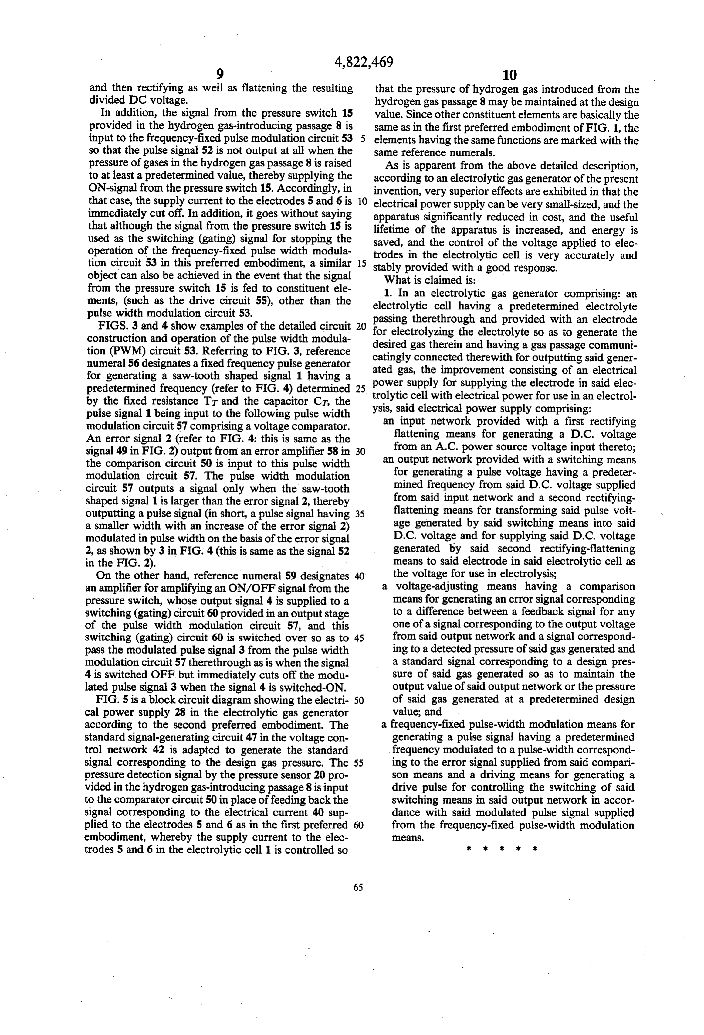
and then rectifying as well as flattening the resulting that the pressure of hydrogen gas introduced from the divided DC voltage. hydrogen gas passage 8 may be maintained at the design In addition, the signal from the pressure switch 15 value. Since other constituent elements are basically the provided in the hydrogen gas-introducing passage 8 is same as in the first preferred embodiment of FIG. 1, the input to the frequency-fixed pulse modulation circuit 53 elements having the same functions are marked with the so that the pulse signal 52 is not output at all when the same reference numerals.
pressure of gases in the hydrogen gas passage 8 is raised As is apparent from the above detailed description, to at least a predetermined value, thereby supplying the according to an electrolytic gas generator of the present ON-signal from the pressure switch 15. Accordingly, in invention, very superior effects are exhibited in that the that case, the supply current to the electrodes 5 and 6 is O electrical power supply can be very small-sized, and the immediately cut off. In addition, it goes without saying apparatus significantly reduced in cost, and the useful that although the signal from the pressure switch 15 is lifetime of the apparatus is increased, and energy is used as the switching (gating) signal for stopping the saved, and the control of the voltage applied to elec operation of the frequency-fixed pulse width modula trodes in the electrolytic cell is very accurately and tion circuit 53 in this preferred embodiment, a similar 15 stably provided with a good response. object can also be achieved in the event that the signal What is claimed is:
from the pressure switch 15 is fed to constituent ele 1. In an electrolytic gas generator comprising: an ments, (such as the drive circuit 55), other than the electrolytic cell having a predetermined electrolyte pulse width modulation circuit 53. passing therethrough and provided with an electrode FIGS. 3 and 4 show examples of the detailed circuit 20 for electrolyzing the electrolyte so as to generate the construction and operation of the pulse width modula desired tion (PWM) circuit 53. Referring to FIG. 3, reference catinglygas therein and having a gas passage communi numeral 56 designates a fixed frequency pulse generator ated gas,connectedthe therewith for outputting said gener improvement consisting of an electrical for generating a saw-tooth shaped signal 1 having a predetermined frequency (refer to FIG. 4) determined 25 power supply for supplying the electrode in said elec trolytic cell with electrical power for use in an electrol by the fixed resistance TT and the capacitor CT, the ysis, said electrical power supply comprising: pulse signal 1 being input to the following pulse width an input network provided with a first rectifying modulation circuit 57 comprising a voltage comparator. flattening means for generating a D.C. voltage An error signal 2 (refer to FIG. 4: this is same as the signal 49 in FIG. 2) output from an error amplifier 58 in 30 anfrom an A.C. power source voltage input thereto; output network provided with a switching means the comparison circuit 50 is input to this pulse width for generating a pulse voltage having a predeter modulation circuit 57. The pulse width modulation mined frequency from said D.C. voltage supplied circuit 57 outputs a signal only when the saw-tooth shaped signal 1 is larger than the error signal 2, thereby from said input network and a second rectifying outputting a pulse signal (in short, a pulse signal having 35 flattening means for transforming said pulse volt a smaller width with an increase of the error signal 2) age generated by said switching means into said modulated in pulse width on the basis of the error signal D.C. voltage and for supplying said D.C. voltage 2, as shown by 3 in FIG. 4 (this is same as the signal 52 generated by said second rectifying-flattening in the FIG. 2). means to said electrode in said electrolytic cell as On the other hand, reference numeral 59 designates the voltage for use in electrolysis; an amplifier for amplifying an ON/OFF signal from the a voltage-adjusting means having a comparison pressure switch, whose output signal 4 is supplied to a means for generating an error signal corresponding Switching (gating) circuit 60 provided in an output stage to a difference between a feedback signal for any of the pulse width modulation circuit 57, and this one of a signal corresponding to the output voltage switching (gating) circuit 60 is switched over so as to 45 from said output network and a signal correspond pass the modulated pulse signal 3 from the pulse width ing to a detected pressure of said gas generated and modulation circuit 57 therethrough as is when the signal a standard signal corresponding to a design pres 4 is switched OFF but immediately cuts off the modu sure of said gas generated so as to maintain the lated pulse signal 3 when the signal 4 is switched-ON. output value of said output network or the pressure FIG. 5 is a block circuit diagram showing the electri 50 of said gas generated at a predetermined design cal power supply 28 in the electrolytic gas generator value; and according to the second preferred embodiment. The a frequency-fixed pulse-width modulation means for standard signal-generating circuit 47 in the voltage con generating a pulse signal having a predetermined trol network 42 is adapted to generate the standard frequency modulated to a pulse-width correspond signal corresponding to the design gas pressure. The 55 ing to the error signal supplied from said compari pressure detection signal by the pressure sensor 20 pro son means and a driving means for generating a vided in the hydrogen gas-introducing passage 8 is input drive pulse for controlling the switching of said to the comparator circuit 50 in place offeeding back the switching means in said output network in accor signal corresponding to the electrical current 40 sup dance with said modulated pulse signal supplied plied to the electrodes 5 and 6 as in the first preferred from the frequency-fixed pulse-width modulation embodiment, whereby the supply current to the elec e2S trodes 5 and 6 in the electrolytic cell 1 is controlled so is
Provenance
- Collection
- Cited prior art
- Original PDF
- patentimages.storage.googleapis.com →
- Filed
- 1988-02-12
- Pages
- 12
- Method
- pdftotext (the PDF's own text layer) + pdftoppm 300dpi page scans
- Source
- Google Patents bibliographic record
- Granted
- 1989-04-18
- Inventors
- Mitsuzo Shimomura; Yoshiro Torii; Stec KK
- Transcribed from
- patentimages.storage.googleapis.com →