patent · US20070284244A1
Electrolysis apparatus with pulsed, dual voltage, multi-composition electrode assembly
13 December 2007
Page 1 — bibliographic record
(19) United States (12) Patent Application Publication (10) Pub. No.: US 2007/0284244 A1
Davidson (43) Pub. Date: Dec. 13, 2007 (54) ELECTROLYSIS APPARATUS WITH Publication Classification PULSED, DUAL VOLTAGE, (51) Int. Cl.
MULT-COMPOSITION ELECTRODE
ASSEMBLY
(52) U.S. Cl. ........................................ 204/274; 204/242 (76) Inventor: Nehemia Davidson, (US) (57) ABSTRACT An electrolysis system (100) is provided. In addition to an
Correspondence Address: electrolysis tank (101) and a membrane (105) separating the Patent Law Office of David G. Beck tank into two regions, the system includes at least one pair P.O.BOX 1146 of low voltage electrodes (115/117) of a first type comprised Mill Valley, CA 94.942 of a first material, at least one pair of low Voltage electrodes (117/118) of a second type comprised of a second material (21) Appl. No.: 11/707.460 different from the first material, and at least one pair of high voltage electrodes (121/122) comprised of a material that (22) Filed: Feb. 13, 2007 may be the same as either the first or second material or different from both the first and second material. The low
Related U.S. Application Data Voltage applied to the low voltage electrodes and the high Voltage applied to the high Voltage electrodes is pulsed with (63) Continuation of application No. 1 1/450,042, filed on the pulses occurring simultaneously with the same pulse Jun. 9, 2006, now abandoned. duration.
HIGH
WOLTAGE
PULSE
125 GENERATOR
Page 2
Drawing sheet — no readable text.
Page 3
Drawing sheet — no readable text.
Page 4
Patent Application Publication Dec. 13, 2007 Sheet 3 of 16 US 2007/0284244 A1
PULSE FREOUENCY
TANK DRAINED
SET 305 -- - -- - - - - - - - - - - - - - - - -- a-- as as as a as a as a 317
PULSE DURATION
SET
TANK CLEANED :
309 s a a 321 ELECTROLYSIS : ELECTRODES - INITIATED REPLACED : 31 O 315
ELECTROLYSS
TANK REFILLED
PROCEEDS
FIG. 3
Page 5
Patent Application Publication Dec. 13, 2007 Sheet 4 of 16 US 2007/0284244 A1
FILL ELECTROLYSIS NITIAL PERIOD OF
OUTPUT
SET INITIAL PULSE
DURATION
PULSE FREQUENCY
OPTIMIZED
ELECTROLYSIS
PULSE DURATION
INITIATED
OPTIMIZED
COMPLETE
SUSPENDED
Page 6
Patent Application Publication Dec. 13, 2007 Sheet 5 of 16 US 2007/0284244 A1
FILL ELECTROLYSIS INITIAL PERIOD OF
OUTPUT
SET INITIAL PULSE PULSE FREOUENCY
DURATION
OPTIMIZED
SET INITIAL HIGH LOWVOLTAGE
OPTIMIZED
MONITOR
HYDROGEN
OUTPUT
FIG. 5
Page 7
Drawing sheet — no readable text.
Page 8
Drawing sheet — no readable text.
Page 9
Drawing sheet — no readable text.
Page 10
Drawing sheet — no readable text.
Page 11
Drawing sheet — no readable text.
Page 12
Drawing sheet — no readable text.
Page 13
Drawing sheet — no readable text.
Page 14
Drawing sheet — no readable text.
Page 15
Drawing sheet — no readable text.
Page 16
Drawing sheet — no readable text.
Page 17
Drawing sheet — no readable text.
Page 18
US 2007/0284244 A1 Dec. 13, 2007
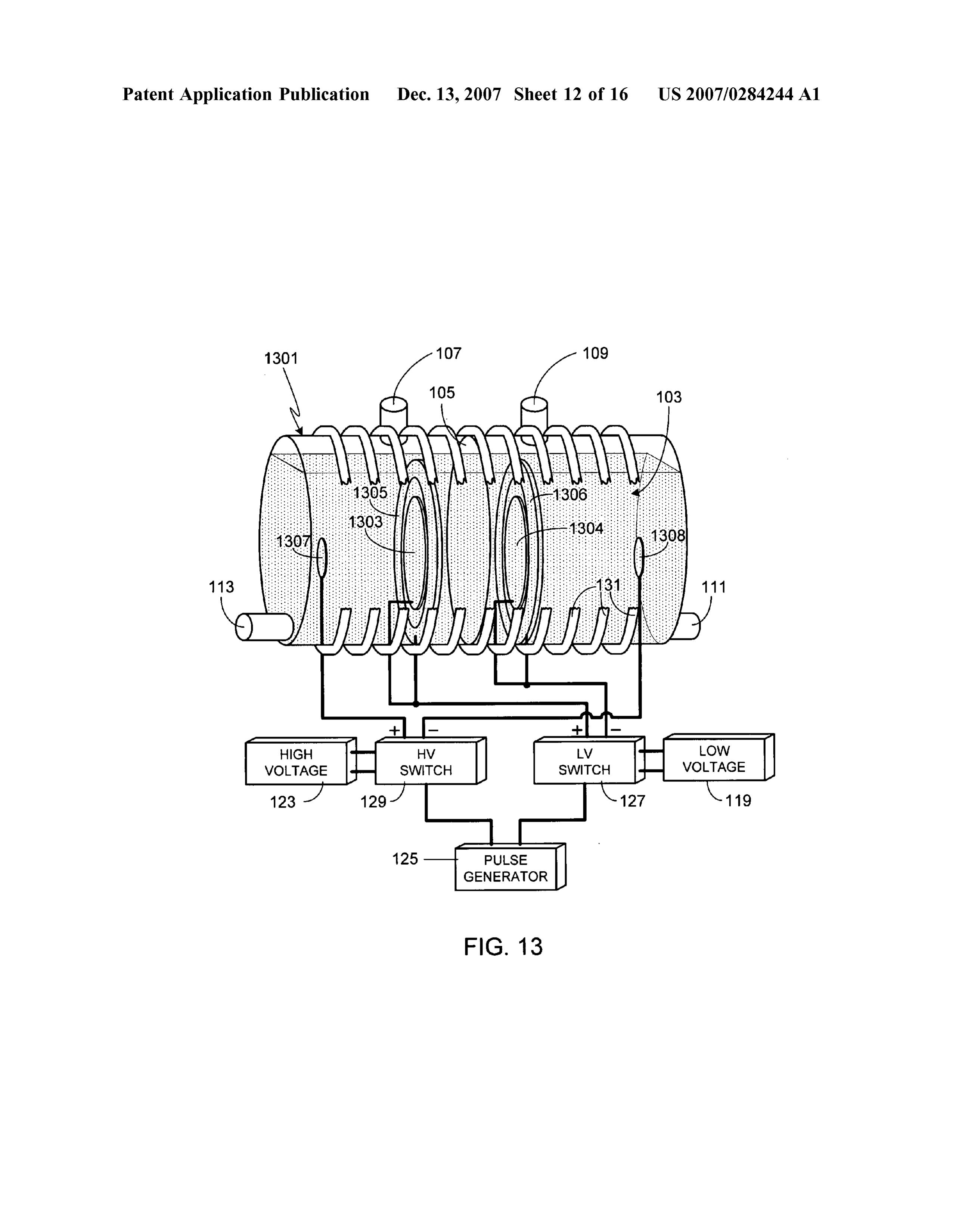
ELECTROLYSIS APPARATUS WITH 0006 Electrolysis as a means of producing hydrogen has PULSED, DUAL VOLTAGE, been known and used for over 80 years. In general, elec MULTI-COMPOSITON ELECTRODE trolysis of water uses two electrodes separated by an ion ASSEMBLY conducting electrolyte. During the process hydrogen is produced at the cathode and oxygen is produced at the
CROSS-REFERENCES TO RELATED anode, the two reaction areas separated by an ion conducting APPLICATIONS diaphragm. Electricity is required to drive the process. An 0001. This application is a continuation of U.S. patent alternative to conventional electrolysis is high temperature application Ser. No. 11/450,042, filed Jun. 9, 2006. electrolysis, also known as steam electrolysis. This process uses heat, for example produced by a Solar concentrator, as
FIELD OF THE INVENTION a portion of the energy required to cause the needed reaction. Although lowering the electrical consumption of the process 0002 The present invention relates generally to elec is desirable, this process has proven difficult to implement trolysis systems and, more particularly, to a high efficiency due to the tendency of the hydrogen and oxygen to recom electrolysis system. bine at the technique's high operating temperatures. 0007 Although a variety of improvements have been
BACKGROUND OF THE INVENTION devised to improve upon the efficiency of the electrolytic 0003) Fossil fuels, in particular oil, coal and natural gas, hydrogen production system, to date none of them have been represent the primary sources of energy in today's world. able to make the process efficient enough to make hydrogen Unfortunately in a world of rapidly increasing energy needs, based fuel a viable alternative to fossil fuels. Accordingly, dependence on any energy source of finite size and limited what is needed in the art is a means for efficiently producing regional availability has dire consequences for the world’s hydrogen, the means preferably being Small enough to economy. In particular, as a country's need for energy minimize the need for an overly complex distribution sys increases, so does its Vulnerability to disruption in the Supply tem. The present invention provides such a system. of that energy source. Additionally, as fossil fuels are the largest single source of carbon dioxide emissions, a green SUMMARY OF THE INVENTION house gas, continued reliance on Such fuels can be expected to lead to continued global warming. Accordingly it is 0008. The present invention provides a system for imperative that alternative, clean and renewable energy achieving high hydrogen output flow rates utilizing elec sources be developed that can replace fossil fuels. trolysis. In addition to an electrolysis tank, a membrane 0004 Hydrogen-based fuel is currently one of the leading separating the tank into two regions, hydrogen gas and contenders to replace fossil fuel. However in order to oxygen gas outlets, and means for filling the tank with successfully transition from oil-based and coal-based fuels electrolyte containing water, the system includes three types to a hydrogen-based fuel, significant improvements must be of electrodes. For each type of electrode, the system includes made in terms of hydrogen production, hydrogen storage at least one pair of electrodes, with each pair of electrodes and distribution, and hydrogen engines. Clearly the state of including a cathode and an anode. the art in each of these developmental areas impacts the 0009. The first and second types of electrodes are con other areas. For example, if a method of inexpensively nected to a low voltage source(s) while the third type of producing hydrogen in Small production plants can be electrode is connected to a high Voltage source. The first and developed, production plants can be situated close to the end second types of electrodes are positioned between the third user, thus avoiding the need for extremely complex and type of electrodes, i.e., the separation distance between the costly distribution systems. high Voltage electrodes is greater than the separation dis 0005. Although a number of techniques can be used to tance of either the first or second types of low voltage produce hydrogen, the primary technique is by Steam electrodes. The power supplied by both the low and high reforming natural gas. In this process thermal energy is used Voltage sources to the three types of electrodes is simulta to react natural gas with Steam, creating hydrogen and neously pulsed, preferably at a frequency between 50 Hz and carbon dioxide. Although this process is well developed, due 5 kHz and with a pulse duration of between 10 nanoseconds to its reliance on fossil fuels and the release of carbon and 0.5 seconds. Preferably the ratio of the high voltage to dioxide during production, it does not alleviate the need for the low voltage is at least 5:1, more preferably within the fossil fuels nor does it lower the environmental impact of its range of 5:1 to 20:1, with a low voltage of between 3 and use over that of traditional fossil fuels. Other, less developed 1500 volts, more preferably within the range of 12 to 750 hydrogen producing techniques include (i) biomass fermen volts, and with a high voltage of between 50 volts and 50 tation in which methane fermentation of high moisture kilovolts, more preferably within the range of 100 volts and content biomass creates fuel gas, a small portion of which is 5 kilovolts. The first and second types of electrodes are hydrogen; (ii) biological water splitting in which certain fabricated from different materials. The first, second and photosynthetic microbes produce hydrogen from water dur third types of electrodes can utilize any combination of ing their metabolic activities; (iii) photoelectrochemical Surface shapes, including flat and curved. Each pair, i.e., processes using either soluble metal complexes as a catalyst cathode and anode, of electrodes of each type can either be or semiconducting electrodes in a photochemical cell; (iv) positioned parallel to one another, or not parallel to one thermochemical water splitting using chemicals such as another. Although the electrodes can be fabricated from a bromine or iodine, assisted by heat, to split water molecules; variety of materials, preferably the material for each elec (v) thermolysis in which concentrated Solar energy is used to trode type is selected from the group consisting of steel, generate temperatures high enough to split methane into nickel, copper, iron, stainless steel, cobalt, manganese, Zinc, hydrogen and carbon; and (vi) electrolysis. titanium, platinum, and alloys thereof.
Page 19
US 2007/0284244 A1 Dec. 13, 2007
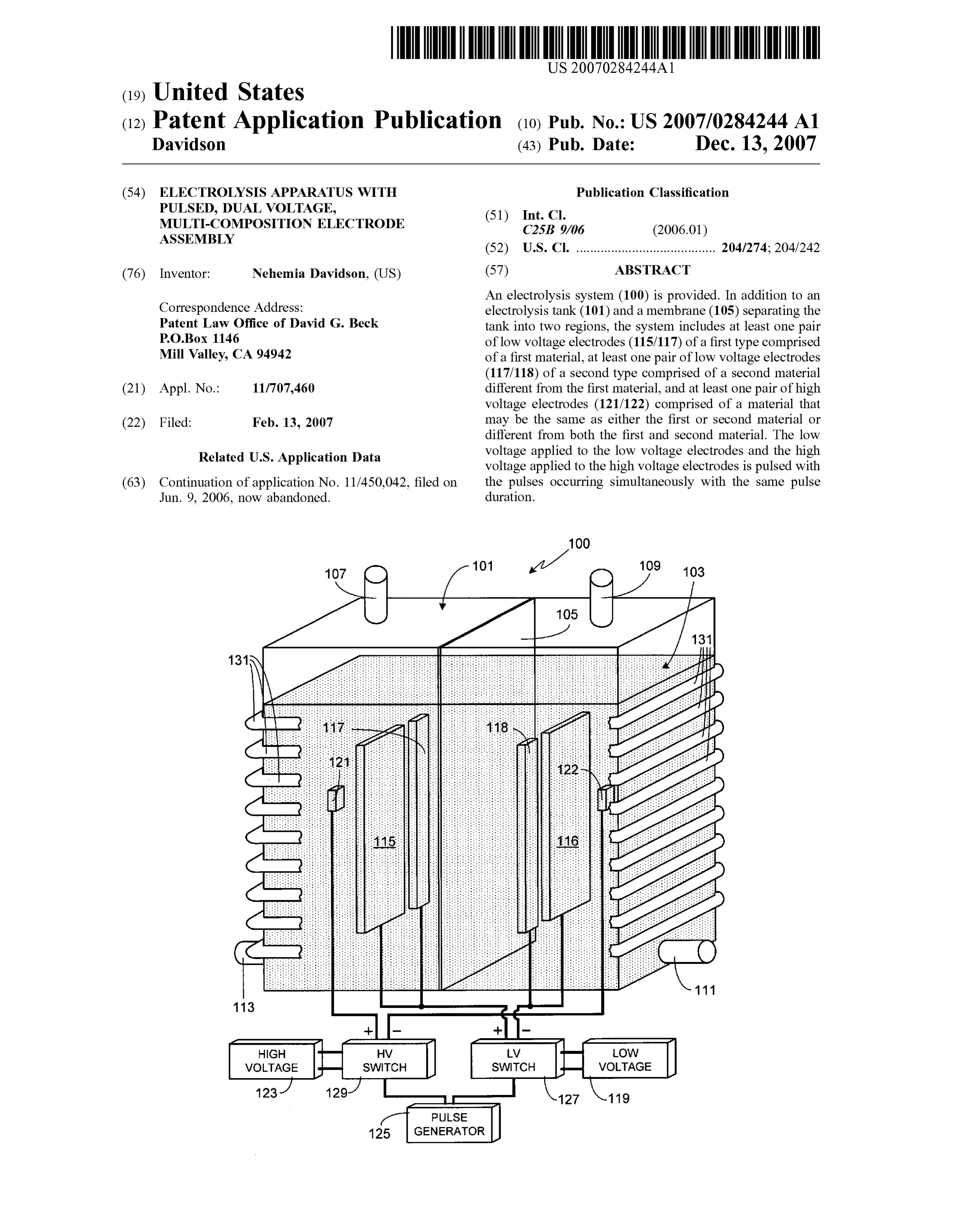
0010. In at least one embodiment of the invention, the material, the size of the tank depending primarily upon the membrane separating the electrolysis tank into two regions desired output level for the system, for example the desired is comprised of polypropylene. quantity/flow rate of hydrogen to be generated. Although 0011. In at least one embodiment of the invention, the tank 101 is shown as having a rectangular shape, it will be concentration of electrolyte in the water is between 0.05 and appreciated that the invention is not so limited and that tank 0.5 percent by weight. Preferably potassium hydroxide is 101 can utilize other shapes, for example cylindrical, square, used as the electrolyte. irregularly-shaped, etc. Tank 101 is substantially filled with 0012. A further understanding of the nature and advan water 103. Within water 103 is an electrolyte, the electrolyte tages of the present invention may be realized by reference necessary to achieve the desired level of conductivity within to the remaining portions of the specification and the draw the water. A preferred electrolyte is potassium hydroxide,
although the invention is not limited to this specific elec
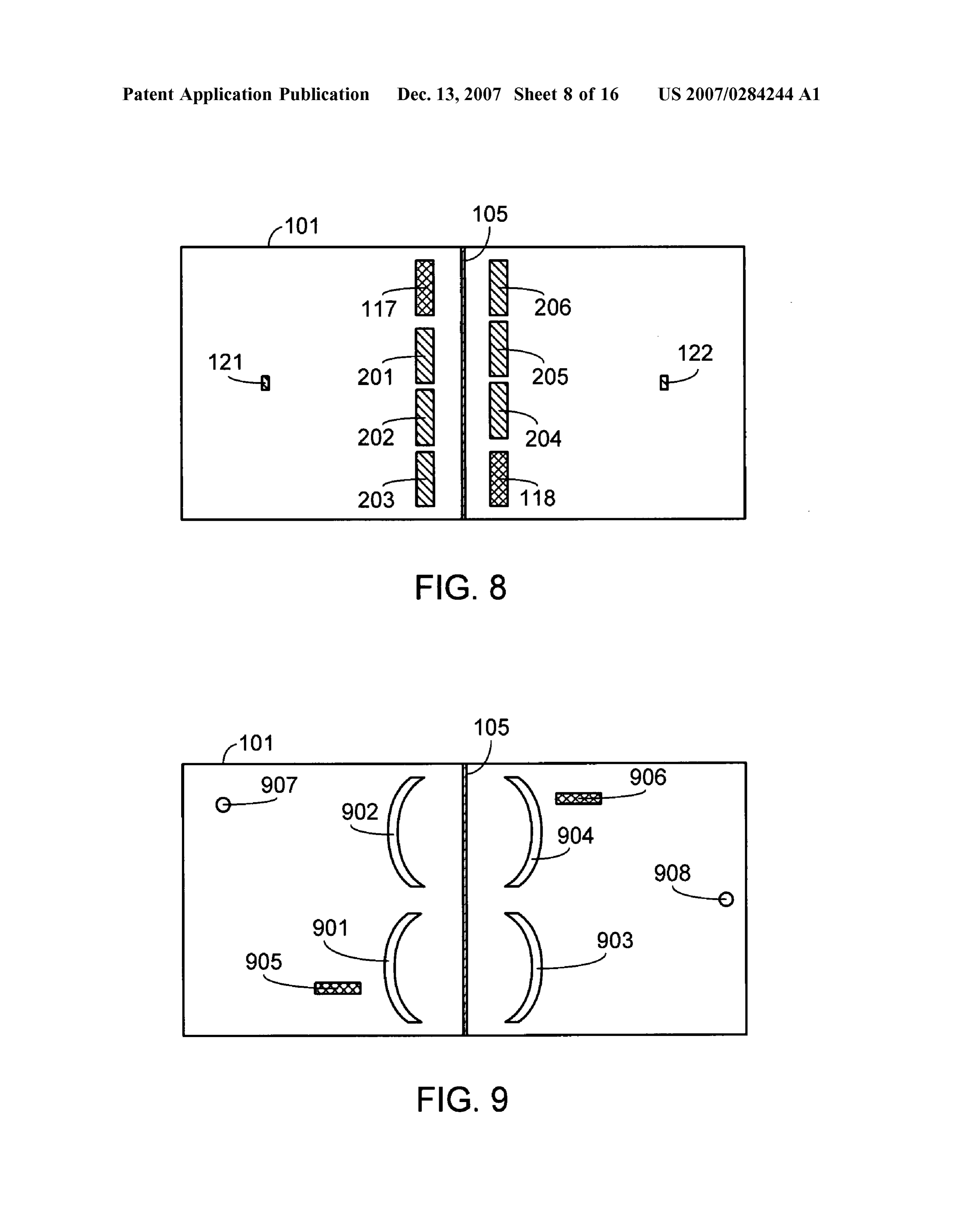
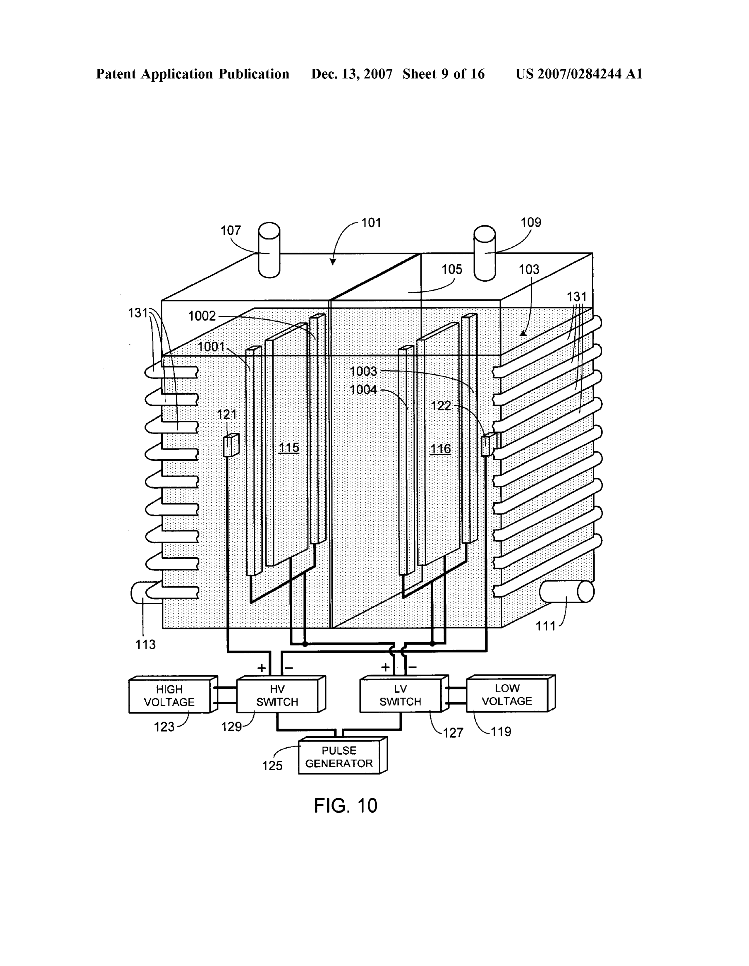
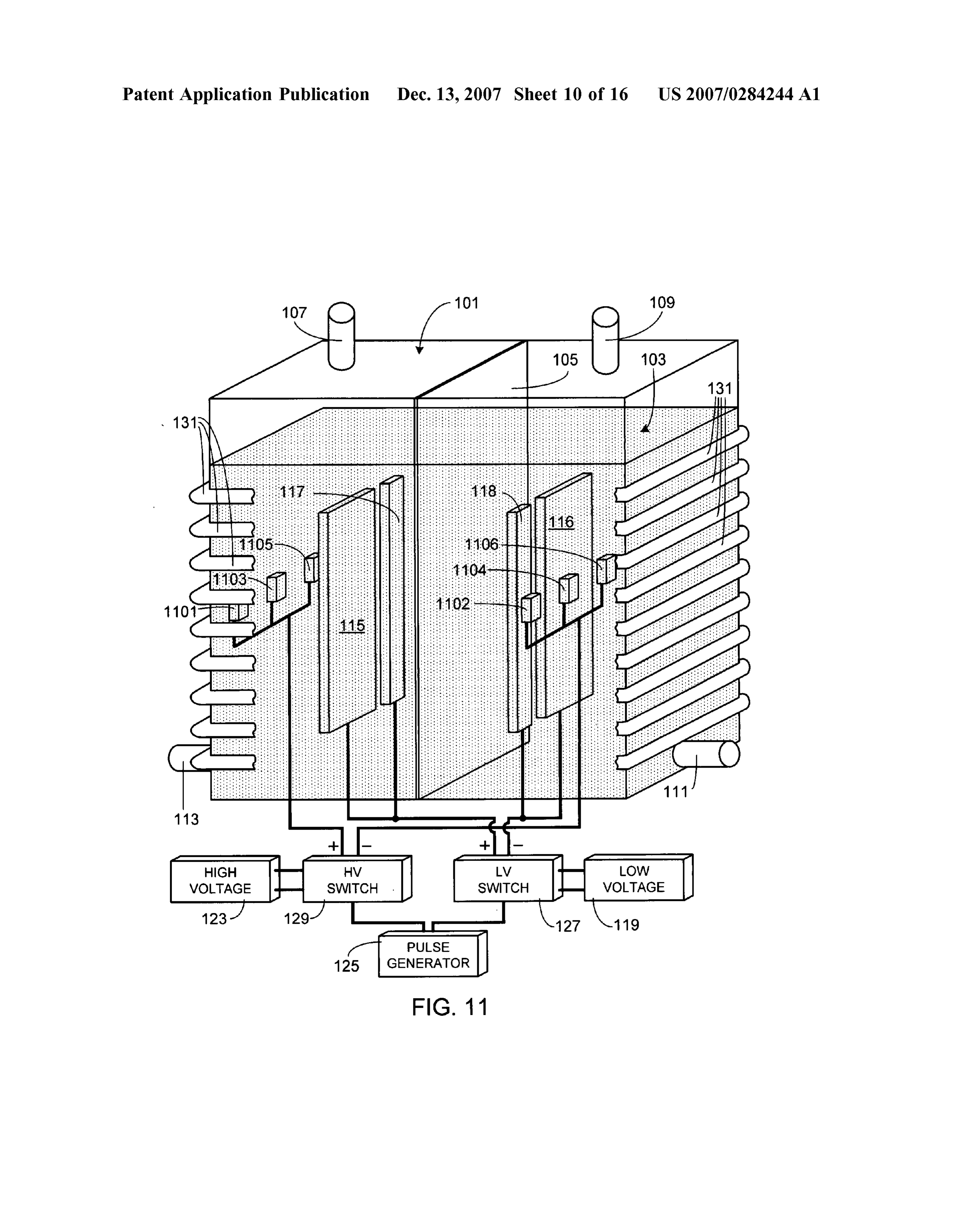
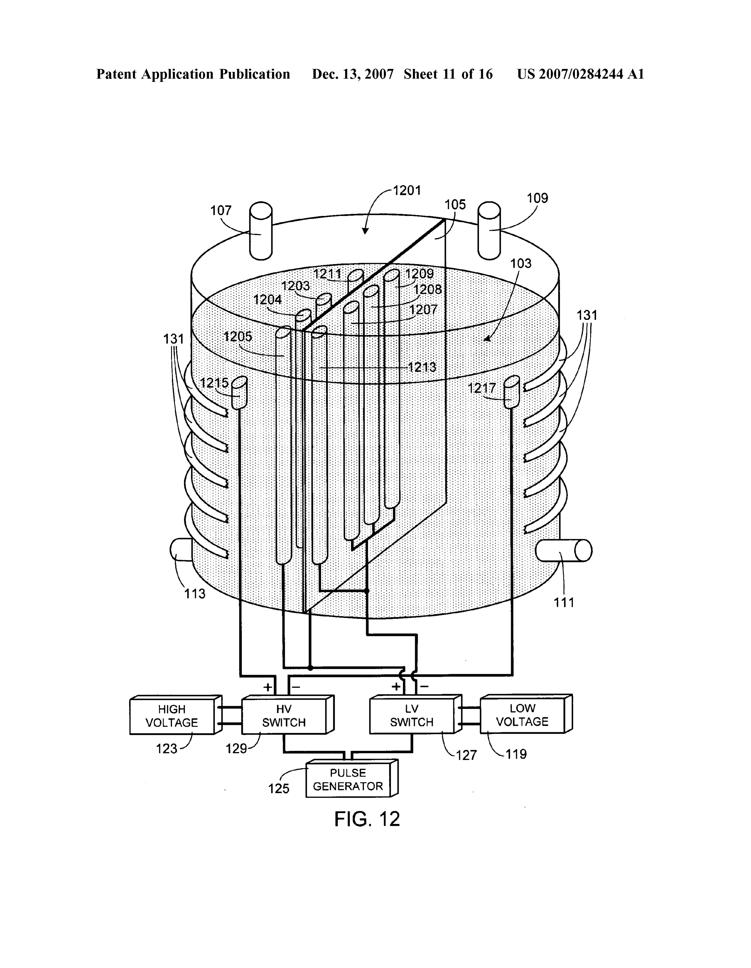
BRIEF DESCRIPTION OF THE DRAWINGS trolyte. For example, sodium hydroxide can also be used. Although a typical electrolysis system used to decompose 0013 FIG. 1 is an illustration of an exemplary, and water into hydrogen and oxygen gases will utilize relatively preferred, embodiment of the invention; high concentrations of electrolyte, the present invention has 0014 FIG. 2 is an illustration of an alternate preferred been found to work best with relatively low electrolyte embodiment utilizing multiple electrodes for one type of low concentrations, thereby maintaining a relatively high water Voltage electrode; resistivity (e.g., typically on the order of 1 to 2 megohms). 0015 FIG. 3 is an illustration of one mode of operation; Note that this resistivity is based on the initial resistance of 0016 FIG. 4 is an illustration of an alternate mode of the water since typically after the system has been operating operation that includes initial process optimization steps: for a while (for example, on the order of 5 to 6 hours), the 0017 FIG. 5 is an illustration of an alternate, and pre resistivity of the water has been found to drop. In at least one ferred, mode of operation in which the process undergoes continuous optimization; preferred embodiment of the invention, an electrolyte con 0018 FIG. 6 is a block diagram illustrating the preferred centration of between 0.05 percent and 0.5 percent by optimization control system; weight, and more preferably an electrolyte concentration of 0.019 FIG. 7 is an illustration of an alternate embodiment 0.2 percent by weight, is used.
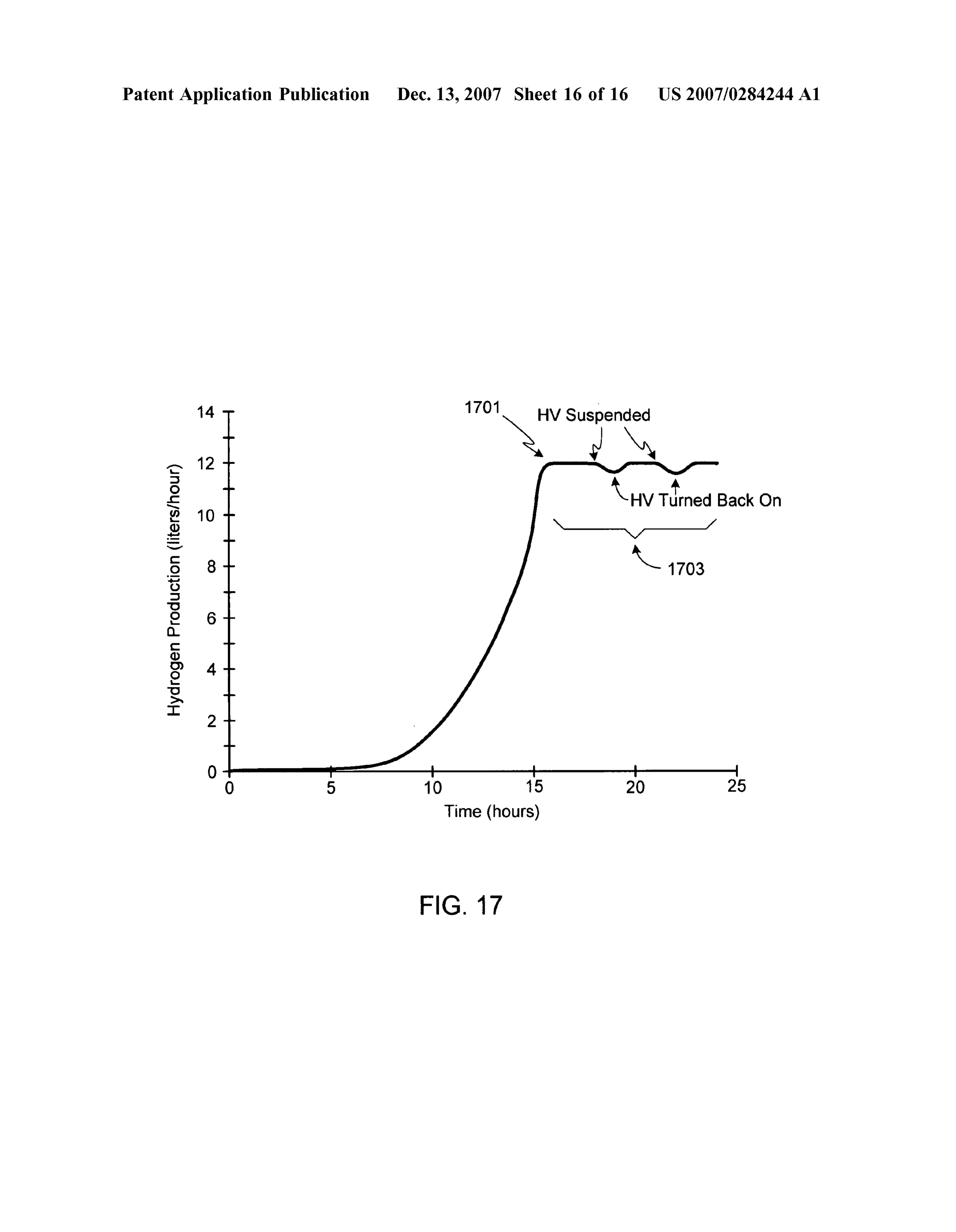
in which the separation distance between one type of low 0031 Separating tank 101 into two regions is a mem voltage electrode is greater than the separation distance brane 105. Membrane 105 permits ion/electron exchange between the second type of low voltage electrode: between the two regions of tank 101 while keeping separate 0020 FIG. 8 is a top, cross-sectional view of the embodi the oxygen and hydrogen bubbles produced during elec ment shown in FIG. 2; trolysis. Maintaining separate hydrogen and oxygen gas 0021 FIG. 9 is a top, cross-sectional view of an alternate regions is important both as a means of allowing the embodiment utilizing shaped electrodes for one type of low collection of pure hydrogen gas and pure oxygen gas, but Voltage electrode; also as a means of minimizing the risk of explosions due to 0022 FIG. 10 is an illustration of an alternate embodi the inadvertent recombination of the two gases. In addition ment utilizing multiple electrodes for the second type of low to permitting ion/electron transfer while segregating the Voltage electrode; produced hydrogen and oxygen gases, the material compris 0023 FIG. 11 is an illustration of an alternate embodi ing membrane 105 is also selected based on its ability to ment utilizing multiple high Voltage electrodes; withstand the temperatures generated by the electrolysis 0024 FIG. 12 is an illustration of an alternate embodi process. Accordingly, in at least one preferred embodiment ment utilizing a cylindrically-shaped tank; the material comprising membrane 105 is selected to be able 0.025 FIG. 13 is an illustration of an alternate embodi to withstand a temperature of at least 90° C. without ment utilizing a cylindrically-shaped tank with a different Suffering from any material degradation. As is well known orientation than the tank of FIG. 12; by those of skill in the art, there are a variety of materials that 0026 FIG. 14 is an illustration of an alternate embodi meet all of these criteria, exemplary materials including ment utilizing a cylindrically-shaped tank with a different polypropylene, tetrafluoroethylene, asbestos, etc. In at least membrane orientation than that utilized in the tank shown in one preferred embodiment, membrane 105 is 25 microns FIG. 13; thick and comprised of polypropylene. 0027 FIG. 15 is an illustration of an alternate embodi 0032. Other standard features of electrolysis tank 101 are ment utilizing multiple low Voltage power Supplies; gas outlets 107 and 109. As hydrogen gas is produced at the 0028 FIG. 16 is an illustration of the hydrogen flow rate cathode and oxygen gas is produced at the anode, in the for a system such as that shown in FIG. 2; and exemplary embodiment shown in FIG. 1 oxygen gas will 0029 FIG. 17 is an illustration of the hydrogen flow rate exit tank 101 through outlet 107 while hydrogen gas will exit for a system in which power to the high Voltage electrodes through outlet 109. Replenishment of the electrolyte con is cycled on/off after maximum flow rate has been achieved. taining water is preferably through a separate conduit, for example conduit 111. In at least one embodiment of the
DESCRIPTION OF THE SPECIFIC invention, another conduit 113 is used to remove water from EMBODIMENTS the system. If desired, a single conduit can be used for both water removal and replenishment. It will be appreciated that 0030 FIG. 1 is an illustration of an exemplary, and a system utilizing electrolysis system 100 to produce hydro preferred, embodiment of the invention which is used to gen will also include means for either storing the produced produce large quantities of hydrogen. Electrolysis system gases, e.g., hydrogen storage tanks, or means for delivering 100 includes a tank 101 comprised of a non-conductive the produced gas to the point of consumption, e.g., pipes and
Page 20
US 2007/0284244 A1 Dec. 13, 2007
Valves, as well as flow gauges, pressure gauges, gas com electrodes 115/116 and 117/118. Additionally the surface pressors, gas driers, gas purifiers, water purifiers, water area of electrodes is much less than either electrodes 115/116 pumps, etc. or electrodes 117/118; for example in one preferred embodi 0033. The electrolysis system of the invention uses three ment the area of electrodes 121/122 is approximately 2 to 3 types of electrodes, each type of electrode being comprised percent the area of electrodes 117/118. Preferably electrodes of one or more electrode pairs with each electrode pair 121/122 are fabricated from titanium, although other mate including a cathode (i.e., a cathode coupled electrode) and rials can be used (e.g., Steel, copper, iron, stainless steel, an anode (i.e., an anode coupled electrode). All cathodes, cobalt, manganese, Zinc, titanium, platinum, and alloys of regardless of the type, are kept in one region of tank 101 these materials).
while all anodes, regardless of the type, are kept in the other 0037. As previously noted, the voltage applied to elec tank region, the two tank regions separated by membrane trode pair 121/122 is greater than that applied to electrodes 105. In the embodiment illustrated in FIG. 1, each type of 115, 116, 117 and 118. Preferably the ratio of the high electrode includes a single pair of electrodes.
0034. The first pair of electrodes, electrodes 115/116, and voltage to the low voltage is between 5:1 and 33:1, and more the second set of electrodes, electrodes 117/118, are both preferably between 5:1 and 20:1. Typically the high voltage low voltage electrodes and, in the illustrated embodiment, generated by source 123 is within the range of 50 volts to 50 coupled to the same voltage source 119. The third set of kilovolts, and preferably within the range of 100 volts to 5 electrodes, electrodes 121/122, are coupled to a high voltage kilovolts. Typically the low voltage generated by source 119 source 123. As described and illustrated, voltage source 119 is within the range of 3 volts to 1500 volts, and preferably is referred to and labeled as a low voltage source not within the range of 12 volts to 750 volts. Rather than because of the absolute voltage produced by the source, but continually apply voltage to the electrodes, sources 119 and because the output of voltage source 119 is maintained at a 123 are pulsed, preferably at a frequency of between 50 Hz lower output voltage than the output of voltage source 123. and 5 kHz with a pulse width (i.e., pulse duration) of Preferably and as shown, the individual electrodes of each between 10 nanoseconds and 0.5 seconds, and more pref pair of electrodes are parallel to one another; i.e., the face of erably with a pulse width of between 10 nanoseconds and electrode 115 is parallel to the face of electrode 116, the face 0.2 seconds. Additionally, the Voltage pulses are applied of electrode 117 is parallel to the face of electrode 118, and simultaneously to electrodes 121/122 via source 123 and the face of electrode 121 is parallel to the face of electrode electrodes 115, 116, 117 and 118 via source 119. In other 122. Additionally, and as shown, in at least one preferred words, the pulses applied to electrodes 121/122 coincide embodiment electrodes 117 and 118 are not positioned with the pulses applied to electrodes 115, 116, 117 and 118. directly across from one another, rather they are on opposite The inventor has found that by simultaneously applying a sides of electrodes 115 and 116 as shown. high voltage to outermost electrodes 121/122 and a low (i.e., 0035 Although electrode pairs 115/116 and 117/118 are lower) voltage to electrodes 115, 116, 117 and 118, the both low voltage electrodes and are preferably coupled to production of hydrogen can be greatly increased over a the same Voltage Supply, these electrode pairs are quite conventional electrolysis system. Although voltage sources different, both in terms of composition and size. In the 119 and 123 can include internal means for pulsing the preferred embodiment electrodes 115/116 are comprised of respective outputs from each source, preferably an external titanium while electrodes 117/118 are comprised of steel. It pulse generator 125 controls a pair of Switches, i.e., low should be appreciated, however, that other materials can be voltage switch 127 and high voltage switch 129 which, in used as long as electrodes 115/116 are made up of a different turn, control the output of voltage sources 119 and 123 as material from electrodes 117/118. In addition to titanium and shown, and as described above.
steel, other exemplary materials that can be used for elec 0038. As previously noted, the electrolysis process of the trode pairs 115/116 and 117/118 include, but are not limited invention generates considerable heat. It will be appreciated to, copper, iron, stainless steel, cobalt, manganese, Zinc, that if the system is allowed to become too hot, the water titanium, platinum, nickel, and alloys of these materials. within the tank will begin to boil. Additionally, other com Preferably the faces of electrodes 115 and 117 are coplanar ponents such as membrane 105 are susceptible to heat as are the faces of electrodes 116 and 118. Also preferably, damage. Although the system can be turned off and allowed the combined area made up by the faces of electrodes 115 to cool when the temperature exceeds a preset value, this is and 117, and similarly the faces of electrodes 116 and 118, not a preferred approach due to the inherent inefficiency of cover approximately 70 percent to 90 percent of the cross stopping the process, allowing the system to cool, and then sectional area of tank 101. Preferably electrodes 117 and 118 restarting the system. Accordingly in the preferred embodi have a much smaller surface area than that of electrodes 115 ments of the invention the system includes means to actively and 116, for example on the order of a sixth of the area. Also cool the system to within an acceptable temperature range. preferably, the height of electrodes 115, 116, 117, and 118 In at least one preferred embodiment, the cooling system are close to the water level of water 103 within tank 101. does not allow the temperature to exceed 90° C. Although it Preferably the separation of the plane containing electrodes will be appreciated that the invention is not limited to a 115 and 117 and the plane containing electrodes 116 and 118 specific type of cooling system or a specific implementation is between 3 millimeters and 15 centimeters, and more of the cooling system, in at least one embodiment the preferably on the order of 10 to 12 centimeters. electrolysis tank is surrounded by a coolant conduit 131, 0036 Electrodes 121/122 are positioned outside of elec portions of which are shown in FIGS. 1, 2, 7, and 10-15. trodes 115/116 and 117/118 (i.e., outside of the planes Within coolant conduit 131 is a heat transfer medium, for containing electrodes 115/116 and 117/118). In other words, example water. The coolant pump and refrigeration system the separation distance between electrodes 121 and 122 is is not shown in the figures as cooling systems are well greater than the distance separating the planes containing known by those of skill in the art.
Page 21
US 2007/0284244 A1 Dec. 13, 2007
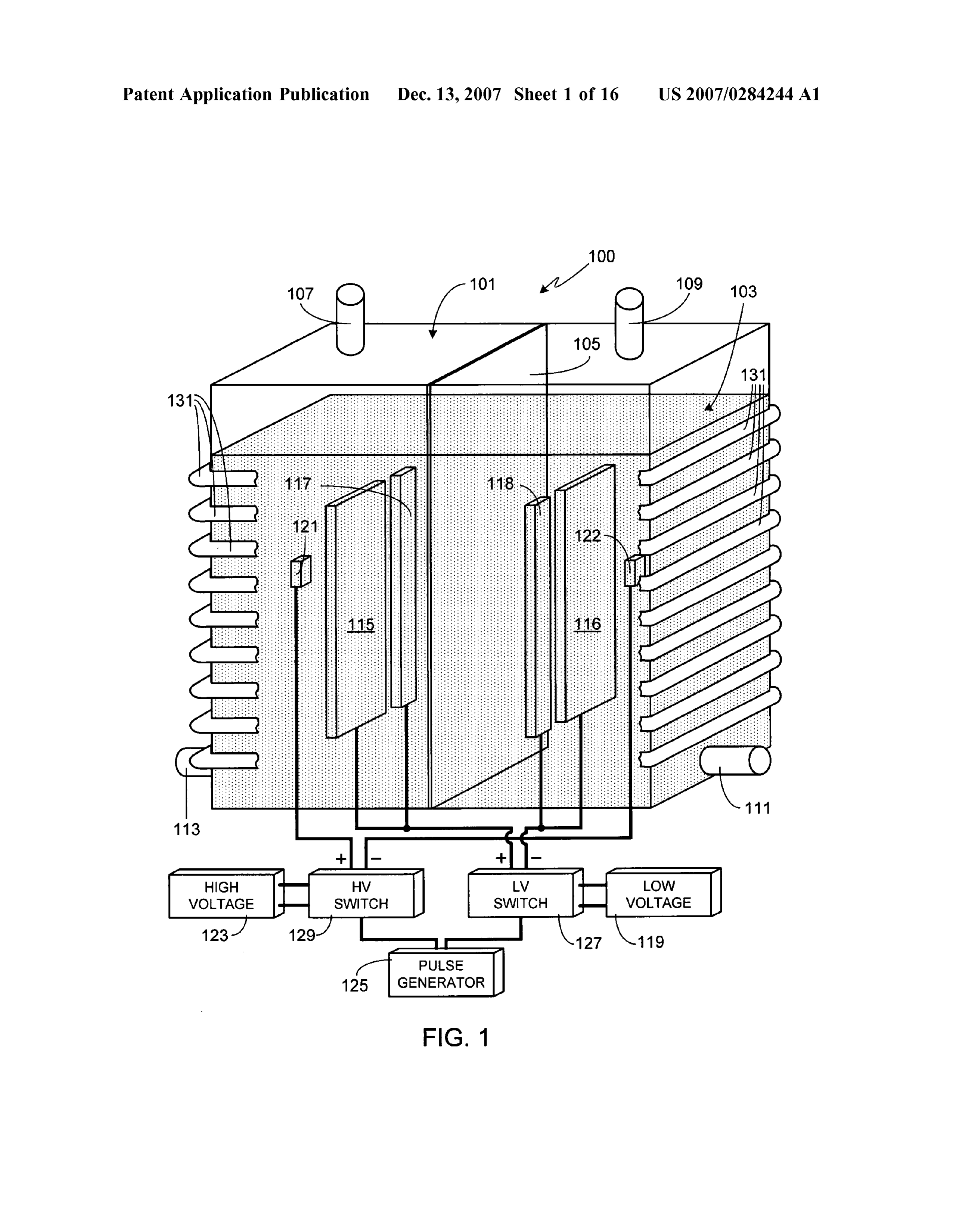
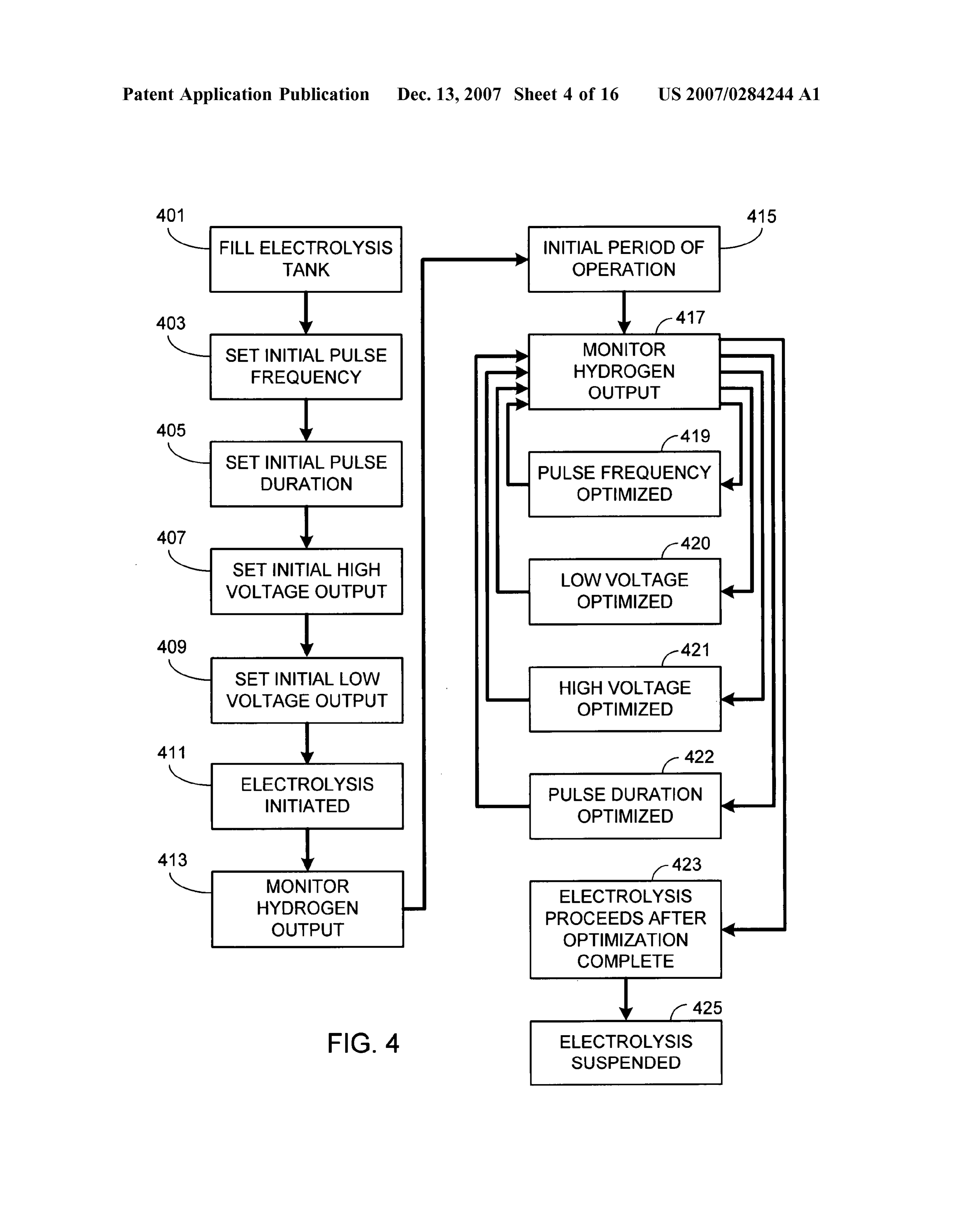
0039. Before describing variations, a specific preferred by washing the electrodes with diluted acids, and/or replac embodiment will be described. In general this embodiment ing spent (i.e., used up) electrodes as necessary (optional has the same configuration as that shown in FIG. 1 except, step 321). After cleaning the system and/or replacing elec as shown in FIG. 2, electrode 115 is replaced by 3 electrodes trodes as necessary, and refilling the system, the system is 201-203 while electrode 116 is replaced by 3 electrodes ready to reinitiate the electrolysis process. 204-206. Electrodes 201-206 were made of rectangular 0043. The above sequence of processing steps works best sheets of titanium, each sheet having an area of 5 centime once the operational parameters have been optimized for a ters by 75 centimeters. Electrodes 117 and 118 were made of specific system configuration since the system configuration rectangular sheets of steel, each having an area of 5 centi will impact the efficiency of the process and therefore the meters by 75 centimeters. Electrodes 121 and 123 were hydrogen output. Exemplary system configuration param made of rectangular sheets of titanium, each sheet having an eters that affect the optimal electrolysis settings include tank area of 2 centimeters by 5 centimeters. The plane containing size, quantity of water, electrolyte composition, electrolyte electrodes 201-203 and 117 was separated from the plane concentration, electrode size, electrode composition, elec containing 204-206 and 118 by 12 centimeters while the trode shape, electrode configuration, electrode separation, separation between electrodes 121 and 122 was 55 centi initial water temperature, low Voltage setting, high Voltage meters. Tank 101 was filled with 180 liters of water, the setting, pulse frequency and pulse duration. water including a potassium hydroxide electrolyte at a 0044 FIG. 4 illustrates an alternate procedure, one in concentration of 0.2% by weight. which the process undergoes optimization. Initially the tank 0040. It should be understood that the present invention is filled (step 401) and initial settings for pulse frequency can be operated in a number of modes, the primary differ (step 403), pulse duration (step 405), high voltage supply ence between the modes being the degree of process opti output (step 407) and low voltage supply output (step 409) mization used during operation. For example, FIG. 3 illus are made. Typically the initial settings are based on previous trates one method of operation requiring minimal settings that have been optimized for a similarly configured optimization. As illustrated, initially the electrolysis tank, system. For example, assuming that the new configuration e.g., tank 101, is filled with water (step 301). The level of was the same as a previous configuration except for the water in the tank preferably just covers the top of the composition of the electrodes, a reasonable initial set-up electrodes although the process can also be run with even would be the optimized set-up from the previous configu more water filling the tank. The electrolyte can either be ration.
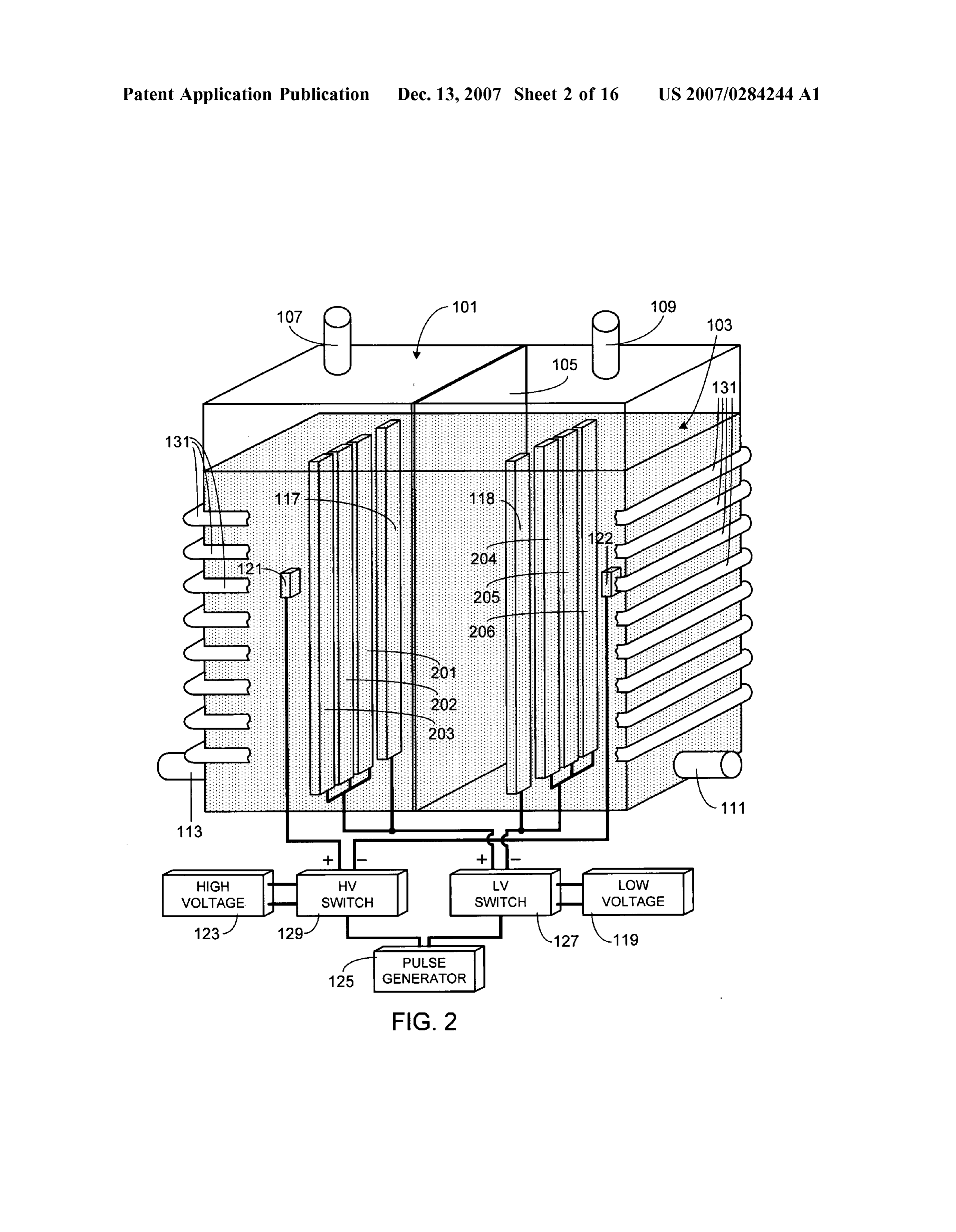
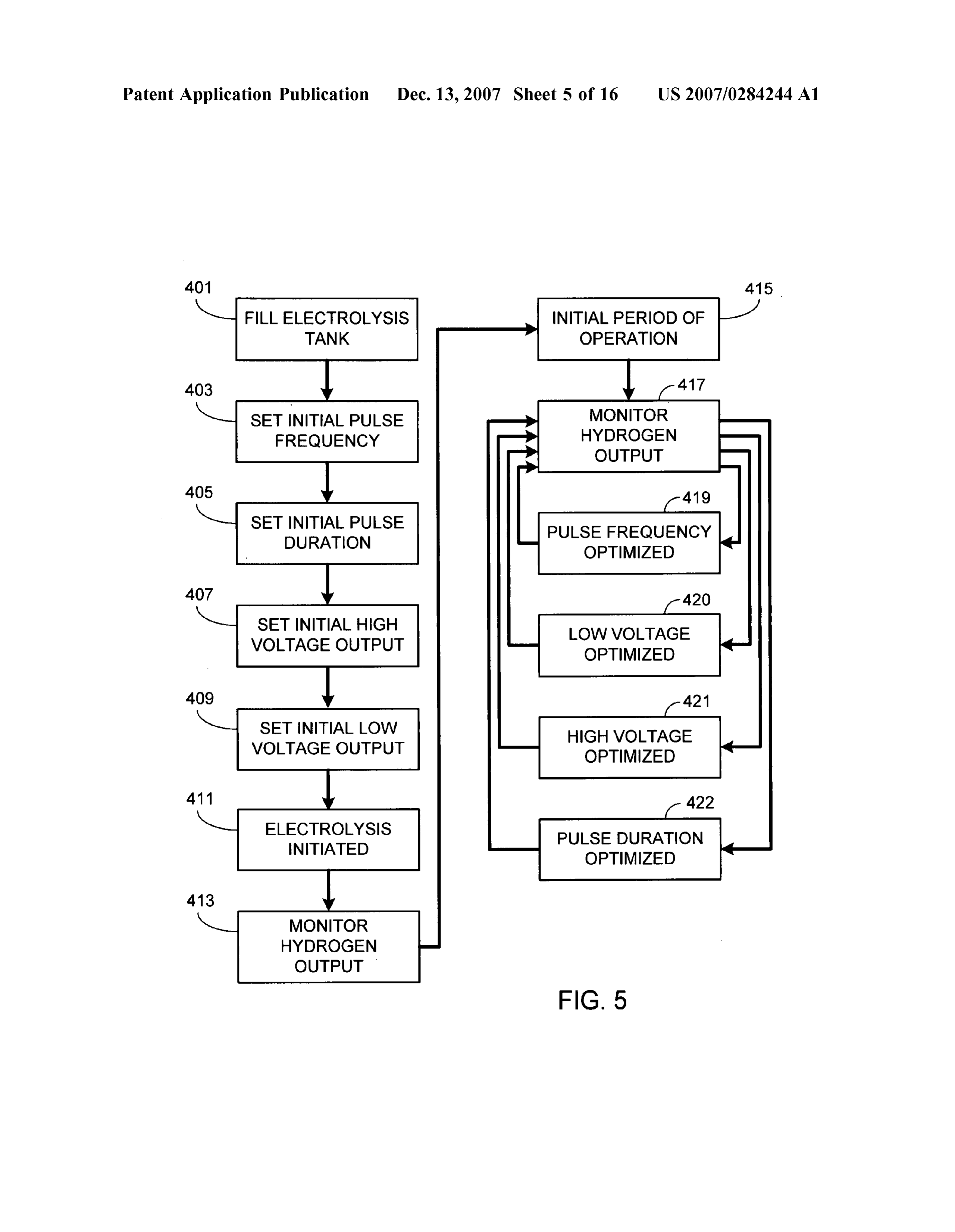
mixed into the water prior to filling the tank or after the tank 0045. After the initial set-up is completed, electrolysis is is filled. The frequency of the pulse generator is then set initiated (step 411) and the hydrogen output flow rate is (step 303) as well as the pulse duration (step 305), the pulse monitored (step 413). Although system optimization can generator controlling the output pulse frequency/duration begin immediately, preferably the system is allowed to run for both voltage supplies. The initial voltage settings for the for an initial period of time (step 415) prior to optimization. low voltage power Supply (e.g., source 119) and the high The initial period of operation can be based on achieving a Voltage power Supply (e.g., Source 123) are also set (step predetermined level of hydrogen flow, for example 50 liters 307). It will be appreciated that the order of set-up is clearly per hour, or achieving a steady state hydrogen flow rate. not critical to the electrolysis process. In the preferred Alternately the initial period of time can simply be a approach, prior to the initiation of electrolysis the tempera predetermined time period, for example 6 hours. ture of the water is at room temperature. 0046. After the initial time period is exceeded, the hydro 0041. Once set-up is complete, electrolysis is initiated gen output is monitored (step 417) while optimizing one or (step 309). During the electrolysis process (step 310), and as more of the operational parameters. Although the order of previously noted, the water is heated by the process itself. parameter optimization is not critical, in at least one pre For example, during operation of an exemplary embodiment ferred embodiment the first parameter to be optimized is the water temperature increased from an initial temperature pulse frequency (step 419). Then the voltage of the low of 25°C. to an average temperature of 70° C., the tempera voltage supply is optimized (step 420) followed by the ture increase occurring over a period of less than 24 hours. optimization of the output voltage of the high Voltage Supply In this exemplary embodiment (i.e., FIG. 2), the pulse (step 421). Lastly the pulse duration is optimized (step 422). frequency was set to 100 Hz, the initial pulse duration was In this embodiment after optimization is complete, based on set to 0.5 milliseconds, the low voltage supply was set to 35 hydrogen output, the electrolysis process is allowed to Volts (drawing approximately 7 amps) and the high Voltage continue (step 423) without further optimization until the Supply was set to 210 volts (drawing approximately 1 amp). process is halted, step 425, for example due to the rate of With this set-up, the system of the invention produced hydrogen production dropping below a user preset level. In hydrogen at an average rate of 10 to 15 liters per hour. In another, and preferred, alternative approach illustrated in comparison, a conventional electrolysis system of similar FIG. 5, optimization steps 419-422 are performed continu capacity will produce approximately 1 liter of hydrogen per ously throughout the electrolysis process until electrolysis is hour. Suspended.
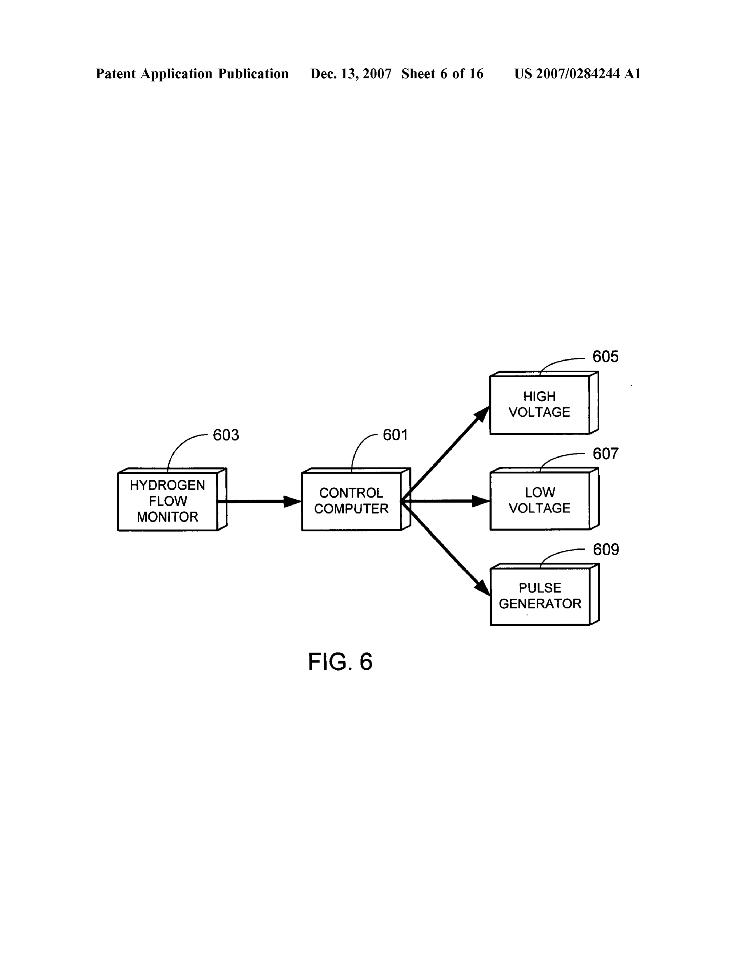
0042 Eventually, after the rate of hydrogen production 0047. The optimization process described relative to drops below a user preset level, the electrolysis process is FIGS. 4 and 5 can be performed manually. In the preferred suspended (step 311) and the water is removed from the tank embodiment, however, the system and the optimization of (step 313). The tank is then refilled (step 315) in order to the system are controlled via computer as illustrated in the prepare it for further electrolysis. If desired, prior to refilling block diagram of FIG. 6. As shown, computer 601 receives the tank, the tank can be washed out (optional step 317). hydrogen flow rate data from monitor 603. Using this Other optional system preparatory steps include cleaning the information computer 601 varies the output of high voltage electrodes to remove oxides (optional step 319), for example source 605, the output of low voltage source 607 and the
Page 22
US 2007/0284244 A1 Dec. 13, 2007
frequency and pulse duration generated by pulse generator replaced with cylindrically-shaped electrode 1213; electrode 609 in order to optimize the output of the system as 121 has been replaced with cylindrical electrode 1215; and previously described. electrode 122 has been replaced with cylindrically-shaped 0048 Although preferably the two types of electrodes electrode 1217.
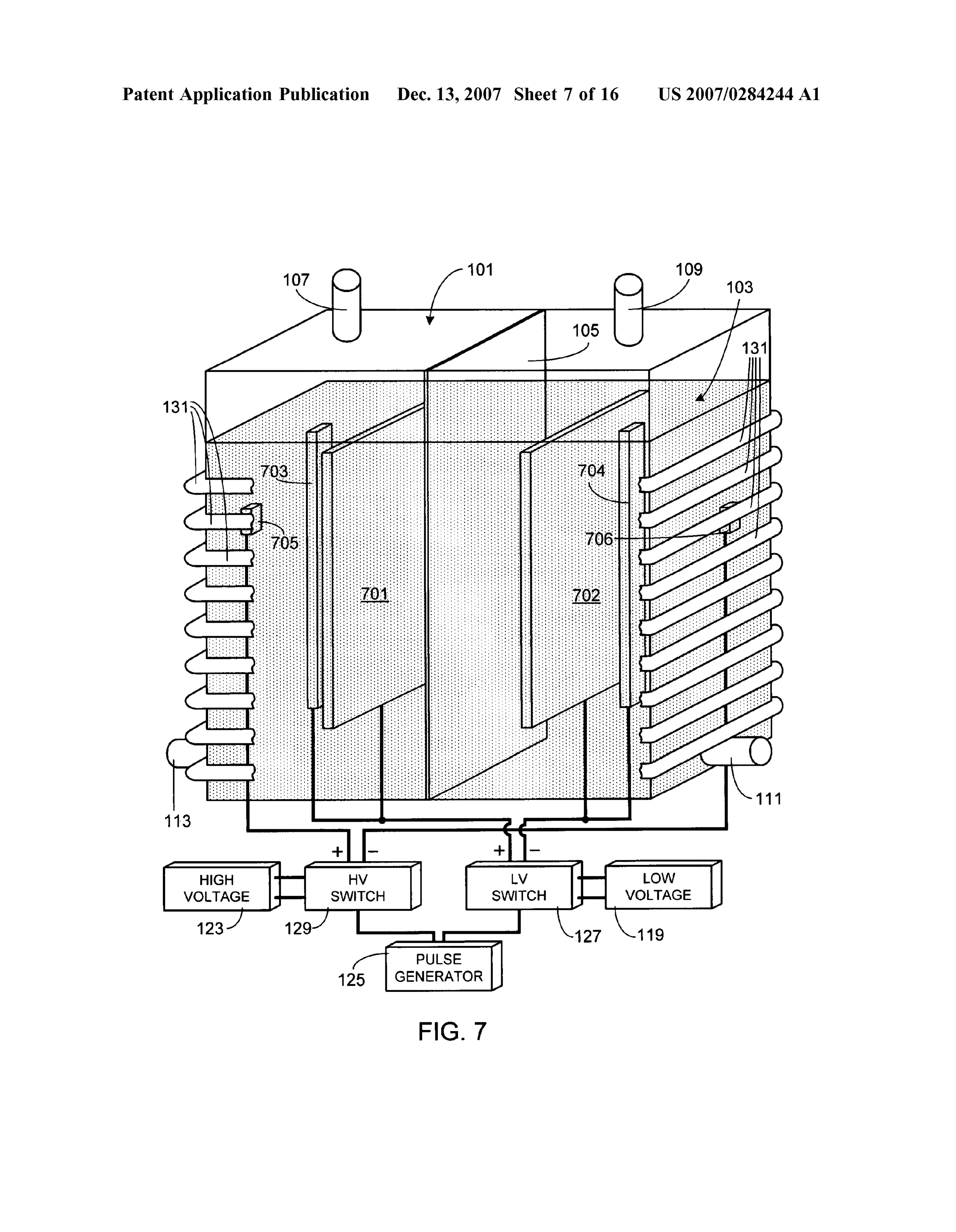
connected to the low Voltage power Supply are arranged in 0053. In yet another alternate embodiment, the system a coplanar fashion as illustrated in FIGS. 1 and 2 (e.g., illustrated in FIG. 13 utilizes a cylindrically-shaped tank 115/116 and 117/118 in FIG. 1 and electrodes 117/201-203 1301 similar to that shown in FIG. 12, except for the and 118/204-205 in FIG. 2), it will be appreciated that such orientation of the tank. As in the embodiment illustrated in arrangement is not a requirement of the invention. For FIG. 1, this embodiment includes a single pair of electrodes example and as illustrated in FIG. 7, the first type of low of each type; disc-shaped electrodes 1303/1304 substituting voltage electrodes (i.e., electrodes 701/702 which corre for electrodes 115/116, ring-shaped electrodes 1305/1306 spond to exemplary electrodes 115/116 of FIG. 1) is sepa substituting for electrodes 117/118, and disc-shaped elec rated by a smaller distance than the second type of low trodes 1307/1308 substituting for electrodes 121/122. As voltage electrodes (i.e., electrodes 703/704 which corre previously noted with respect to the invention in general, the spond to exemplary electrodes 117/118 of FIG. 1). Thus, as invention is not limited to specific electrode numbers, shown, the two types of low voltage electrodes are not shapes, sizes or orientations.
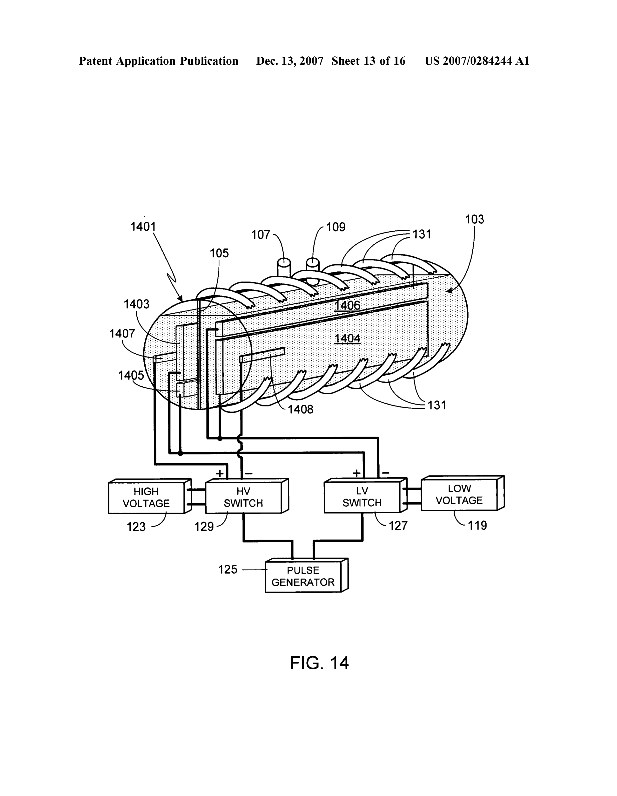
coplanar. As in the previous embodiments, the high Voltage 0054. In yet another alternate embodiment, the system electrodes 705/706 are positioned outside the planes of the illustrated in FIG. 14 utilizes a cylindrically-shaped tank low Voltage electrodes. 1401 similar to that shown in FIG. 13, except for the 0049. As previously described, preferably the electrodes orientation of the membrane and electrodes. As in the are flat and arranged such that the flat electrodes faces are embodiment illustrated in FIG. 1, this embodiment includes parallel to one another. For example, another view of the a single pair of electrodes of each type; electrodes 1403/ system shown in FIG. 2 is provided in FIG. 8, the latter view 1404 substituting for electrodes 115/116, electrodes 1405/ being a top, cross-sectional view of the electrode configu 1406 substituting for electrodes 117/118, and electrodes ration. It should be appreciated that Such a configuration is 1407/1408 substituting for electrodes 121/122. As previ not a requirement of the invention. For example, Some or all ously noted with respect to the invention in general, the of the electrodes can utilize curved surfaces and/or be invention is not limited to specific electrode numbers, arranged in a non-parallel geometry. Examples of some shapes, sizes or orientations. It should also be noted that variations are shown in the top, cross-sectional view of FIG. typically electrodes 1407/1408 are centered length-wise 9. In this exemplary embodiment one type of low voltage within tank 1401; however, the electrodes are shown non electrode, corresponding to electrodes 115/116 of FIG. 1, centered in FIG. 14 so that they are visible in this view, i.e., have curved electrode faces (i.e., electrodes 901-904) while so that electrode 1407 is not hidden from view by electrode the second type of low Voltage electrode, corresponding to 1403 and membrane 105.
electrodes 117/118 of FIG. 1, have flat faces that are per 0055. It will be appreciated that although all of the pendicular to the membrane and positioned near the walls of illustrated embodiments show only a single low voltage the tank (i.e., electrodes 905/906). The third type of elec source coupled to both types of low voltage electrodes, two trodes, the high Voltage electrodes corresponding to elec separate low voltage sources 1501 and 1503 can be used as trodes 121/122 of FIG. 1, are cylindrically shaped and shown in FIG. 15. Although this configuration is similar to positioned near the outermost walls of the tank and outside that shown in FIG. 1 except for the use of multiple low of the two types of low voltage electrodes (i.e., electrodes voltage sources, it will be understood that multiple low 907/908). Voltage sources can be used with any of the illustrated 0050. As previously described, FIG. 2 illustrates an alter embodiments. The constraints placed on both low voltage nate embodiment of the system shown in FIG. 1 utilizing source 1501 and low voltage source 1503 are the same as three electrodes 201-203 of the type represented by elec placed on low voltage source 119 of the previous embodi trode 115 in FIG. 1, and three electrodes 204-206 of the type ments, for example the preferred ratio of the high voltage to represented by electrode 116 in FIG. 1. In another alternate the low voltage (of both low voltage sources) is between 5:1 embodiment of the system shown in FIG. 1, and as shown and 33:1, and more preferably between 5:1 and 20:1. Simi in FIG. 10, electrode 117 is replaced by two electrodes 1001 larly, it should be understood that the invention can utilize and 1002 while electrode 118 is replaced by two electrodes multiple high Voltage sources. For example, in the embodi 1003 and 1004. ment illustrated in FIG. 11 in which multiple high voltage 0051. In yet another alternate embodiment, shown in electrodes are used, multiple high Voltage sources could be FIG. 11, the system includes multiple high voltage electrode coupled to these electrodes.
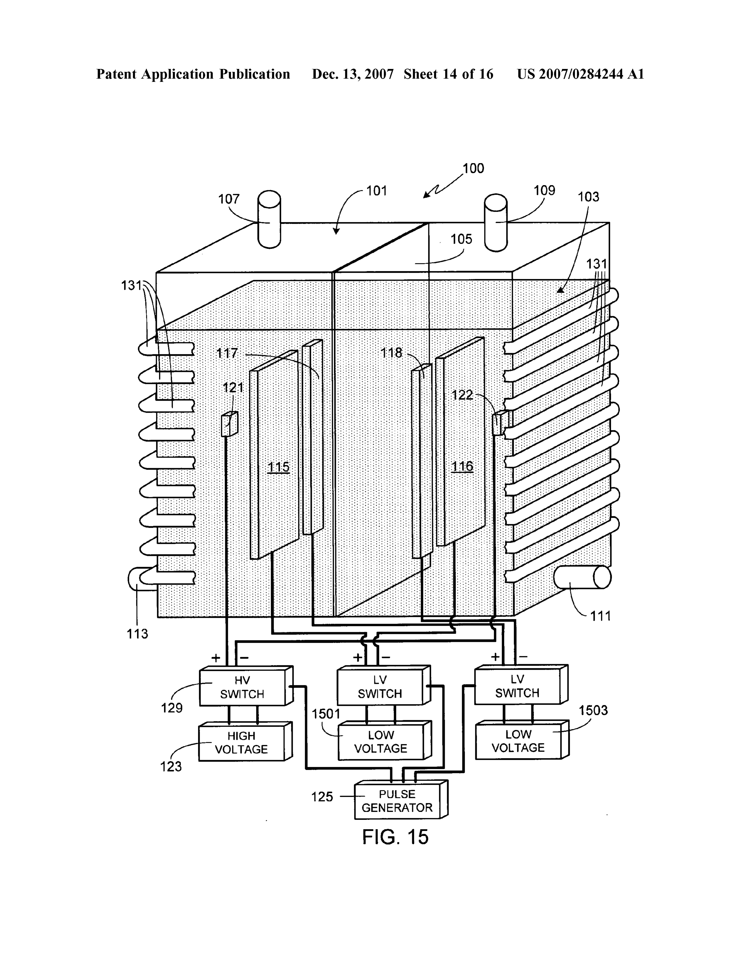
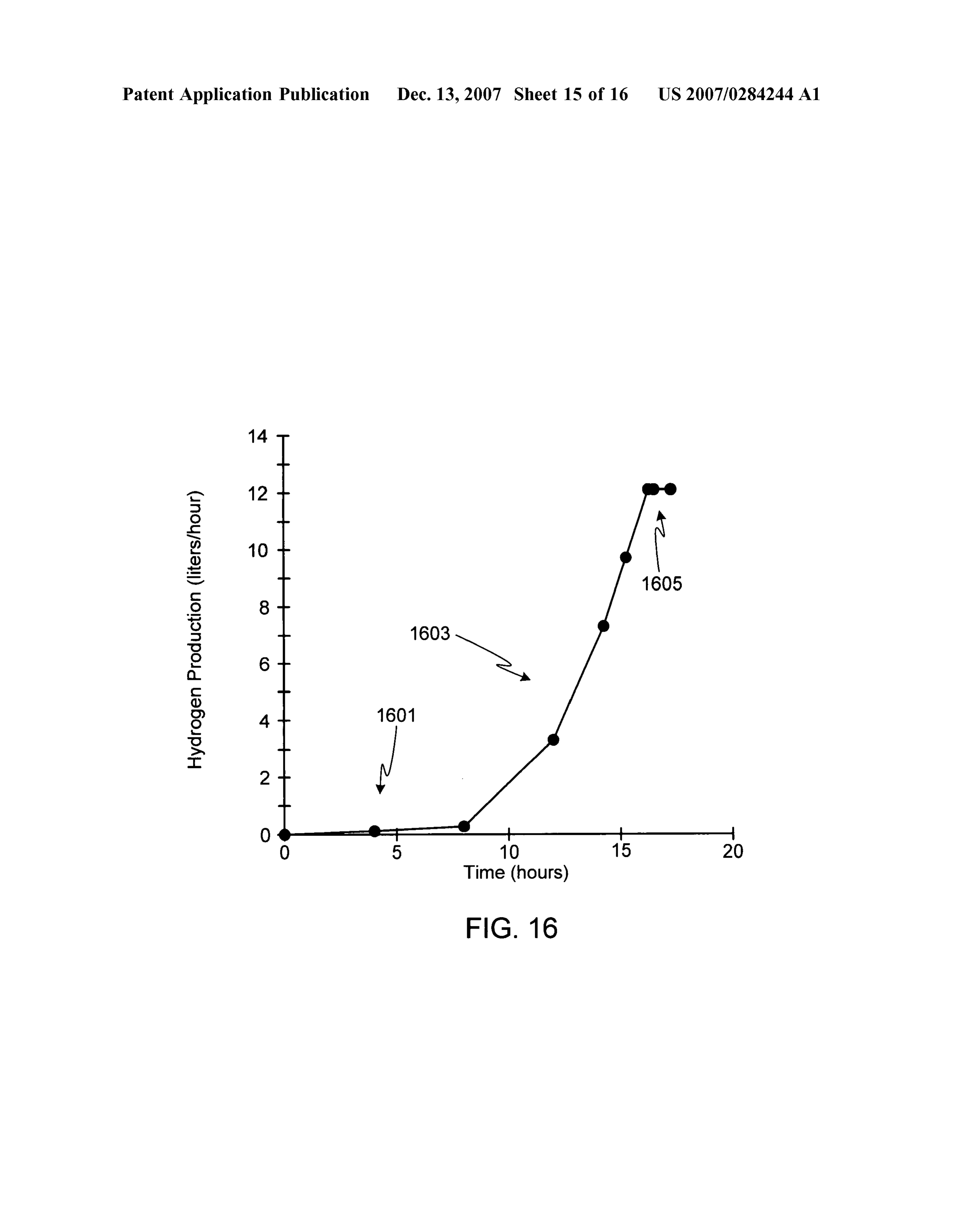
pairs (101/1102, 1103/1104, and 1105/1106). 0056. As previously noted, the use of high voltage elec 0052. As previously noted, the present invention is not trodes in conjunction with two types of low voltage elec limited to a specific tank shape. FIG. 12 illustrates an trodes (i.e., electrodes of different composition), leads to a embodiment similar to that shown in FIG. 2 utilizing an major increase in hydrogen production. For example, FIG. alternate tank shape, specifically a horizontally-positioned, 16 illustrates the hydrogen flow rate for a system similar to cylindrically-shaped tank 1201. Although a cylindrical tank that shown in FIG. 2. As shown, during the initial period of does not restrict the type of electrode, in the illustrated time, typically on the order of the first 5 to 8 hours of embodiment electrodes 201-203 have been replaced with operation, the hydrogen flow rate is similar to that of a cylindrically-shaped electrodes 1203–1205; electrodes 204 conventional system (i.e., region 1601). After this initial 206 have been replaced with cylindrically-shaped electrodes period of time, however, the rate undergoes a dramatic 1207-1209; electrode 117 has been replaced with cylindri increase (i.e., region 1603) until the hydrogen flow rate cally-shaped electrode 1211; electrode 118 has been reaches a plateau (i.e., region 1605) for that particular
Page 23
US 2007/0284244 A1 Dec. 13, 2007
system. Operation at the higher flow rate will continue until, said at least one pair of low voltage electrodes of said eventually, it becomes necessary to replace the water in second type includes an anode and a cathode: order to maintain the desired hydrogen flow rate/conversion at least one pair of high Voltage electrodes contained efficiency. within said electrolysis tank, wherein each pair of said 0057. In order to conserve input energy, the inventor has at least one pair of high Voltage electrodes includes an found that once the high flow plateau has been reached (e.g., anode and a cathode, wherein said anodes of said first region 1605 in FIG. 16), this output level, or close to this and second types of low Voltage electrodes and said output level, will continue for a period of time after power anodes of said high Voltage electrodes are contained to the high voltage electrodes has been terminated. However, within said first region and said cathodes of said first if voltage is re-applied to the high voltage electrodes before and second types of low Voltage electrodes and said the output flow is allowed to significantly decrease, the cathodes of said high Voltage electrodes are contained output flow rate quickly rises back to the previous maxi within said second region, wherein a first separation mum. Accordingly the high Voltage can be cycled on and off distance corresponding to the distance between the high to achieve a high output rate while minimizing input power. Voltage electrodes of each pair of said at least one pair FIG. 17 is an illustrative flow rate for such a system. As of high Voltage electrodes is greater than a second shown, after the maximum flow rate for the system is separation distance corresponding to the distance reached (i.e., region 1701), the high voltage electrodes are between the low voltage electrodes of each pair of said cycled on and off (i.e., region 1703). In the illustrated at least one pair of low voltage electrodes of said first example, the high Voltage is applied for 2 hours, then type, and wherein said first separation distance is Suspended for 1 hour, then applied for 2 hours, etc., this greater than a third separation distance corresponding process continuing until the water must be replaced in order to the distance between the low voltage electrodes of to maintain the desired hydrogen flow rate/conversion effi each pair of said at least one pair of low Voltage ciency. Note that in a preferred implementation of this aspect electrodes of said second type; of the invention, high Voltage cycling is based on hydrogen a low Voltage source with a first output voltage electri output, not a strict time line. Thus, for example, once Voltage cally connected to said at least one pair of low Voltage to the high Voltage electrodes has been Suspended, it would electrodes of said first type and to said at least one pair not be re-applied until the output flow drops below a user of low Voltage electrodes of said second type; preset level, for example when the flow rate drops by 5 percent of the maximum flow rate. At that time high voltage a high Voltage source with a second output voltage would be re-applied to the high voltage electrodes until the electrically connected to said at least one pair of high output flow rate re-stabilizes at the higher flow rate. Cycling Voltage electrodes, wherein said second output voltage would then continue using hydrogen flow rate to determine is higher than said first output Voltage; and when to turn-on/turn-off the high voltage electrodes. means for simultaneously pulsing both said low Voltage 0058 As will be understood by those familiar with the Source and said high voltage source at a specific art, the present invention may be embodied in other specific frequency and a specific pulse duration. forms without departing from the spirit or essential charac 2. The electrolysis system of claim 1, further comprising teristics thereof. For example, although the preferred use of means for cooling said electrolysis system. the apparatus is as a hydrogen generator, the system can also 3. The electrolysis system of claim 2, wherein said be used as a heat Source since the apparatus generates cooling means is comprised of a conduit containing a heat considerable heat during use. Accordingly, the disclosures transfer medium, wherein a portion of said conduit is in and descriptions herein are intended to be illustrative, but thermal communication with at least a portion of said not limiting, of the scope of the invention which is set forth electrolysis tank.
in the following claims. 4. The electrolysis system of claim 3, wherein said heat What is claimed is: transfer medium is comprised of water. 1. An electrolysis system comprising: 5. The electrolysis system of claim 1, wherein said an electrolysis tank; simultaneous pulsing means comprises a pulse generator a membrane separating said electrolysis tank into a first coupled to said low Voltage source and to said high Voltage
SOUC.
region and a second region, wherein said membrane 6. The electrolysis system of claim 1, wherein said permits ion and electron exchange between said first simultaneous pulsing means comprises a pulse generator and second regions, and wherein said membrane coupled to a low Voltage Switch and coupled to a high restricts hydrogen gas flow and oxygen gas flow Voltage Switch, wherein said low voltage Switch is coupled between said first and second regions; to said low Voltage source, and wherein said high Voltage at least one pair of low voltage electrodes of a first type Switch is coupled to said high Voltage source. contained within said electrolysis tank, said at least one pair of low Voltage electrodes of said first type com 7. The electrolysis system of claim 1, wherein said prised of a first material, wherein each pair of said at simultaneous pulsing means comprises a first internal pulse least one pair of low voltage electrodes of said first type generator coupled to said low Voltage source and a second includes an anode and a cathode: internal pulse generator coupled to said high Voltage source. at least one pair of low Voltage electrodes of a second type 8. The electrolysis system of claim 1, wherein said contained within said electrolysis tank, said at least one membrane is comprised of polypropylene. pair of low voltage electrodes of said second type 9. The electrolysis system of claim 1, wherein a ratio of comprised of a second material, wherein said first and said second output Voltage to said first output voltage is at second materials are different, and wherein each pair of least 5 to 1.
Page 24
US 2007/0284244 A1 Dec. 13, 2007
10. The electrolysis system of claim 1, wherein a ratio of electrodes of said second type are positioned between said said second output voltage to said first output voltage is high Voltage electrodes of said at least one pair of high within the range of 5:1 to 20:1. Voltage electrodes.
11. The electrolysis system of claim 1, further comprising 21. The electrolysis system of claim 1, wherein all low water within said electrolysis tank, said water including voltage cathode electrodes of said first type and all low between 0.05 and 0.5 percent by weight of an electrolyte. Voltage cathode electrodes of said second type are posi 12. The electrolysis system of claim 11, wherein said tioned in a first plane, and wherein all low Voltage anode electrolyte is comprised of potassium hydroxide. electrodes of said first type and all low voltage anode 13. The electrolysis system of claim 1, wherein said first electrodes of said second type are positioned in a second output voltage is between 3 volts and 1500 volts and said plane.
second output voltage is between 50 volts and 50 kilovolts. 22. The electrolysis system of claim 1, wherein each low 14. The electrolysis system of claim 1, wherein said first Voltage electrode of said at least one pair of low Voltage output voltage is between 12 volts and 750 volts and said electrodes of said first type is flat. 23. The electrolysis system of claim 1, wherein each low second output voltage is between 100 volts and 5 kilovolts. Voltage electrode of said at least one pair of low Voltage 15. The electrolysis system of claim 1, wherein a ratio of electrodes of said first type is curved. a first Surface area corresponding to each low voltage 24. The electrolysis system of claim 1, wherein each low electrode of said first type and a second Surface area corre Voltage electrode of said at least one pair of low Voltage sponding to each low Voltage electrode of said second type electrodes of said second type is flat. is greater than 6 to 1. 25. The electrolysis system of claim 1, wherein each low 16. The electrolysis system of claim 1, wherein a first Voltage electrode of said at least one pair of low Voltage Surface area corresponding to each high Voltage electrode is electrodes of said second type is curved. less than three percent of a second Surface area correspond 26. The electrolysis system of claim 1, wherein each high ing to each low voltage electrode of said first type. Voltage electrode of said at least one pair of high Voltage 17. The electrolysis system of claim 1, wherein said first electrodes is flat.
material is selected from the group consisting of steel, 27. The electrolysis system of claim 1, wherein each high nickel, copper, iron, stainless steel, cobalt, manganese, Zinc, Voltage electrode of said at least one pair of high Voltage titanium, platinum, and alloys of Steel, nickel, copper, iron, electrodes is curved.
stainless steel, cobalt, manganese, Zinc, titanium, and plati 28. The electrolysis system of claim 1, wherein said low num, wherein said second material is selected from the Voltage source is comprised of a first power Supply electri group consisting of steel, nickel, copper, iron, stainless steel, cally connected to said at least one pair of low voltage cobalt, manganese, Zinc, titanium, platinum, and alloys of electrodes of said first type and a second power Supply steel, nickel, copper, iron, stainless steel, cobalt, manganese, electrically connected to said at least one pair of low voltage Zinc, titanium, and platinum, and wherein each high Voltage electrodes of said second type.
electrode is comprised of a material selected from the group 29. The electrolysis system of claim 1, wherein the low consisting of steel, nickel, copper, iron, stainless steel, Voltage electrodes of said at least one pair of low Voltage cobalt, manganese, Zinc, titanium, platinum, and alloys of electrodes of said first type are positioned parallel to one another.
steel, nickel, copper, iron, stainless steel, cobalt, manganese, 30. The electrolysis system of claim 1, wherein the low Zinc, titanium, and platinum. Voltage electrodes of said at least one pair of low Voltage 18. The electrolysis system of claim 1, wherein said electrodes of said second type are positioned parallel to one second separation distance between the low Voltage elec another.
trodes of each pair of said at least one pair of low Voltage 31. The electrolysis system of claim 1, wherein the high electrodes of said first type is between 3 millimeters and 15 Voltage electrodes of said at least one pair of high Voltage centimeters.
19. The electrolysis system of claim 1, wherein said third electrodes are positioned parallel to one another. separation distance between the low voltage electrodes of 32. The electrolysis system of claim 1, wherein said each pair of said at least one pair of low Voltage electrodes specific frequency is between 50 Hz, and 5 kHz. of said second type is between 3 millimeters and 15 centi 33. The electrolysis system of claim 1, wherein said meters. specific pulse duration is between 10 nanoseconds and 0.5 seconds.
20. The electrolysis system of claim 1, wherein all low
Voltage electrodes of said first type and all low Voltage
Provenance
- Collection
- Patents citing this work
- Pages
- 24
- Method
- pdftotext (the PDF's own text layer) + pdftoppm 300dpi page scans
- Patent office record
- patents.google.com →
- Source
- Google Patents citing-documents table
- Assignee
- Nehemia Davidson
- Inventors
- Nehemia Davidson
- Published
- 2007-12-13
- Transcribed from
- patentimages.storage.googleapis.com →