patent · US2101168
Electrical precipitation apparatus
7 December 1937
Page 1
Drawing sheet — no readable text.
Page 2
Patented Dec. 7, 1937 2,101,168
UNITED STATES PATENT OFFICE 2,10,168
ELECTRICAL PRECIPITATION APPARATUS
Walther Deutsch, Frankfort-on-the-Main, Ger many, assignor to international Precipitation
Company, Los Angeles, Calif., a corporation of
California
Application February 23, 1937, Serial No. 12,287
In Germany February 24, 1936
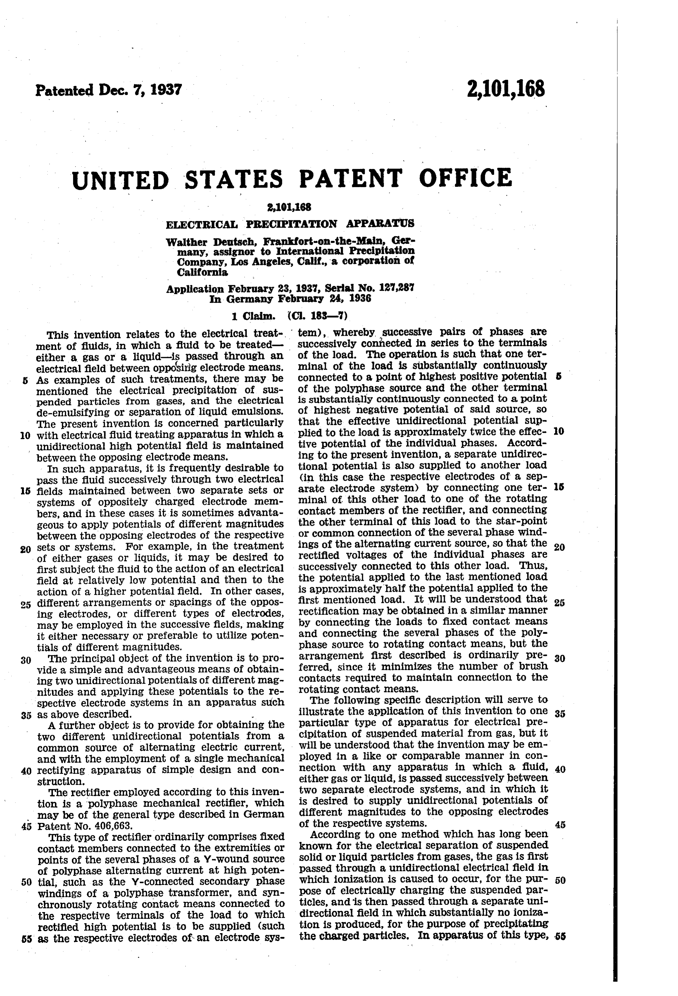
This invention Irelates to the electrical treate tem), whereby successive pairs of phases are ment of fluids, in which a fluid to be treated successively connected in series to the terminals either a gas or a liquid-is passed through an of the load. The Operation is such that one ter electrical field between opposing electrode means. minal of the load is substantially continuously As examples of such treatments, there may be connected to a point of highest positive potential mentioned the electrical precipitation of sus of the polyphase source and the other terminal pended particles from gases, and the electrical is substantially continuously connected to a point de-emulsifying Or separation of liquid emulsions. of highest negative potential of said source, so The present invention is concerned particularly that the effective unidirectional potential sup O with electrical fluid treating apparatus in which a plied to the load is approximately twice the effec O unidirectional high potential field is maintained tive potential of the individual phases. Accord between the opposing electrode means. ing to the present invention, a separate unidirec In such apparatus, it is frequently desirable to tional potential is also supplied to another load pass the fluid successively through two electrical (in this case the respective electrodes of a sep 5 fields maintained between two separate sets or arate electrode system) by connecting one ter s systems of oppositely charged electrode mem minal of this other load to one of the rotating contact members of the rectifier, and connecting bers, and in these cases it is sometimes advanta the geous to apply potentials of different magnitudes other terminal of this load to the star-point between the opposing electrodes of the respective or common Connection of the several phase wind 20 sets or systems. For example, in the treatment ings of the alternating current source, so that the 20 of either gases or liquids, it may be desired to rectified voltages of the individual phases are first subject the fiuid to the action of an electrical successively connected to this other load. Thus, field at relatively low potential and then to the the potential applied to the last mentioned load action of a higher potential field. In other cases, is approximately half the potential applied to the different arrangements or spacings of the oppos first mentioned load. It will be understood that 25 ing electrodes, or different types of electrodes, by rectification may be obtained in a similar manner may be employed in the successive fields, making connecting the loads to fixed contact means it either necessary or preferable to utilize poten and connecting the several phases of the poly tials of different magnitudes. phase source to rotating contact means, but the 30 The principal object of the invention is to pro arrangement first described is ordinarily pre 30 vide a simple and advantageous means of obtain ferred, since it minimizes the number of brush ing two unidirectional potentials of different mag contacts required to maintain connection to the nitudes and applying these potentials to the re rotating contact means.
Spective electrode systems in an apparatus such The following specific description will serve to 35 as above described. illustrate the application of this invention to one 35 A further object is to provide for obtaining the particular type of apparatus for electrical pre two different unidirectional potentials from a cipitation of suspended material from gas, but it common source of alternating electric current, will be understood that the invention may be em and with the employment of a single mechanical ployed in a like or comparable manner in con 40 rectifying apparatus of simple design and con nection with any apparatus in which a fluid, 40 struction. either gas or liquid, is passed successively between The rectifier employed according to this inven tWO Separate electrode systems, and in which it tion is a polyphase mechanical rectifier, which is desired to supply unidirectional potentials of may be of the general type described in German different magnitudes to the opposing electrodes 45 Patent No. 406,663. of the respective systems. 45 This type of rectifier ordinarily comprises fixed According to one method which has long been contact members connected to the extremities or known for the electrical separation of suspended points of the Several phases of a Y-wound source Solid or liquid particles from gases, the gas is first of polyphase alternating current at high poten passed through a unidirectional electrical field in 50 tial, such as the Y-connected secondary phase which ionization is caused to occur, for the pur 50 windings of a polyphase transformer, and syn ticles,pose of electrically charging the suspended par chronously rotating contact means connected to and is then passed through a separate uni the respective terminals of the load to which directional field in which substantially no ioniza rectified high potential is to be Supplied (such tion is produced, for the purpose of precipitating 55 as the respective electrodes of an electrode sys the charged particles. In apparatus of this type, 55
Page 3
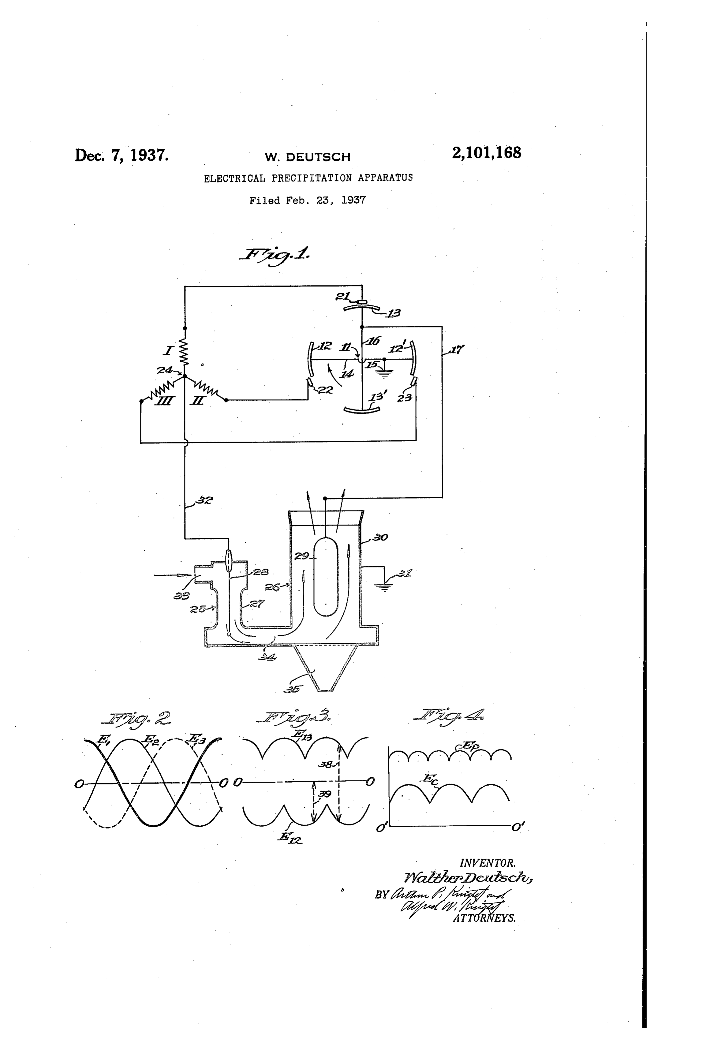
- some difficulty has been encountered in obtainiag arrangement. Tae contact segments 3 and 3' Suficient ionization in the first or charging field are also electrically connected together as indi to effectively charge the suspended particles, cated at 5, alad are connected by conductor without causing an objectionably large proportion to one of the electrodes of one electrode systern 5 of the suspended particles to be actually precip of the precipitator as hereinafter described . The 5 . . itated in this field instead of in the second or contact segments 3 and 3' are at high poten precipitating field in which, according to this tial with respect to ground and the connection method, the actual separation may be naore ad -thereof to conductor Laay be nade by means of Wantageously carried Ot. a brush or other stitable contact device. O For the above reason, it is advantageOIS in he rectifier further comprises three fixed con- O sone cases to pass the gas through the charging tact Imembers 2, 22 and 23 spaced 120 apart in field at a velocity several times as great as the position for effective spark contact with the rotat velocity at which it is passed through the pre ing contact segmeats and connected respectively cipitating field. This may be accomplished ad to the extrenities of the several paase windings 5 wantageously by placing the electrodes relatively I, II and L. The inaer ends of the several is close together in the charging field, to provide a phases are connected together at a common point gas passage space therebetween of relatively Small 2, commonly referred to as the star-point. k Cross-Sectional area, and placing the electrodes It will be understood that the rotating contact relatively farther apart in the precipitating field, assembly of the rectifier may be mounted in the to provide a gas passage space therebetween uSlai Inanner upon the shaft of a synchronous 2D Whose cross-sectional area is Several times that notor for rotationia the proper direction, for ex of the charging field. For example, the charging anaple as shown by the arrow in Fig. 1, and that electrode system may comprise a discharging suitable insulating araeans are provided for elec electrode formed as a wire of sufficiently small trically installating the segaerats 2 and 2' and diameter to provide effective corona, discharge or conductor fron segments 13 and 3' and con- 25 ionization, disposed axially within a substantially ductor 16. Owing to the fact that the device is cylindrical tube or pipe which constitutes the op shown as provided with two contact segments posing non-discharging electrode of extended for each polarity of the rectified potential, the surface, while the precipitating electrode Systern rotating asserably is operated at one-half syn 3) may comprise two concentric cylindrical electrode chronous Speed, as by means of a four-pole syn- 30 members, both of sufficiently extended surface to chronous motor, so that 80 rotation thereof cor substantially prevent corona dischargetherefroia, responds to 360 electrica degrees. It will beta and spaced from one another by a distance SOrne derstood, however, that only one rotating contact what greater than the spacing of the two elec segment for each polarity may be provided, in 35 trodes of the charging field, so as to provide the which case the two segments would be located as desired increase in cross-sectional area of the gas 180 apart in space, and the rotating assembly passage space therebetween. would be operated at synchronous speed. With such an arrangement, it becomes desir The electrical precipitator is shown as com able to apply a higher potential to the electrodesprising a charging zone or field 25 and a precip of the precipitating electrode system than to the tating Zone or field 26. The electrode system electrodes of the charging electrode system, and the charging fied comprises a non-di the arraragement according to the preSeat in Vera pipe electrode 2 aad a discharge electrodernen tion may be employed advantageously for this ber 23, such as a wire orthelike, extending axial
The accompanying drawing illustrates the in
ily within said pipe and insulated therefrom. The electrode System of the precipitating zone con vention as applied to an apparatus of this type, prises a Laon-discharging cyliadrical electrode and referring thereto: f Gaernber 29 of stificiently extended surface, and Fig. 1 is a diagrammatic representation of an preferably rounded at its ends as shown, to pre electrical precipitation apparatus of the type vent corona discharge therefron, and a pipe or 50 above described and an aSSociated electric circuit arrangement according to this invention;
cylindrical electrode member 30, concentrically
Surrounding and insulated from the electrode 2).
Fig. 2 is a diagram of the polyphase potential Electrodes 2 and 3 are electrically grounded as supplied by the alternating current source; indicated at 3. the other electrode 2 of the Fig. 3 is a diagraria representing the positive precipitating electrode Systera is connected 55 and negative potentials applied to the respective through the above inentioned conductor 7 to the is rotating contact members of the rectifier; and high tension contact segments 3 and 3, while Fig. 4 is a diagram of the rectified potentials the other electrode 28 of the charging electrode supplied to the respective electrode systems, it Systeria is connected by conductor 32 to the above being understood that the relationships shown in nentioned star-point car coranca connection of 80 Figs. 3 and 4 are somewhat idealized for purposes the taree plaases I, I and II of the alternating of illustration. Current Sorce.
Referring to Fig. , the secondary phase wind The gas to be cleaned enters the charging zone ings of a high potentia three-phase transformer at 33 and is conducted from this zone by a fie or are shown at , and . pipe connection 34 to the precipitating zone. The The rectifier comprises a rotating assembly in ckeaned gas is discharged from the open upper dicated diagrammatically at provided with two (end of the tubular electrode 30, and suitable diametrically opposed contact segments 2 and f2' means, such as a hopper 35, are provided below and another pair of diametrically opposed contact the precipitaling Zone for receiving and collect segments 3 and 3’ disposed circumferentially ing the precipitated raateria. .
70 Inidway between the contact segments 2 and 2. Referring to Fig. 2, the potentials of the several The contact segments 2 and i2' are electrically phase windings I, II and II (and consequently connected together as at 4 and are shown as the potentials maintained at the fixed contacts 2, grounded at 5. This connection may be made 22 and 23) are represented at E. E. and Es, re either through the shaft of the rotating assembly Spectively. This figure represents approximately 5 or by means of a brush or other suitable contact one full cycle of alternating current, in which is
Page 4
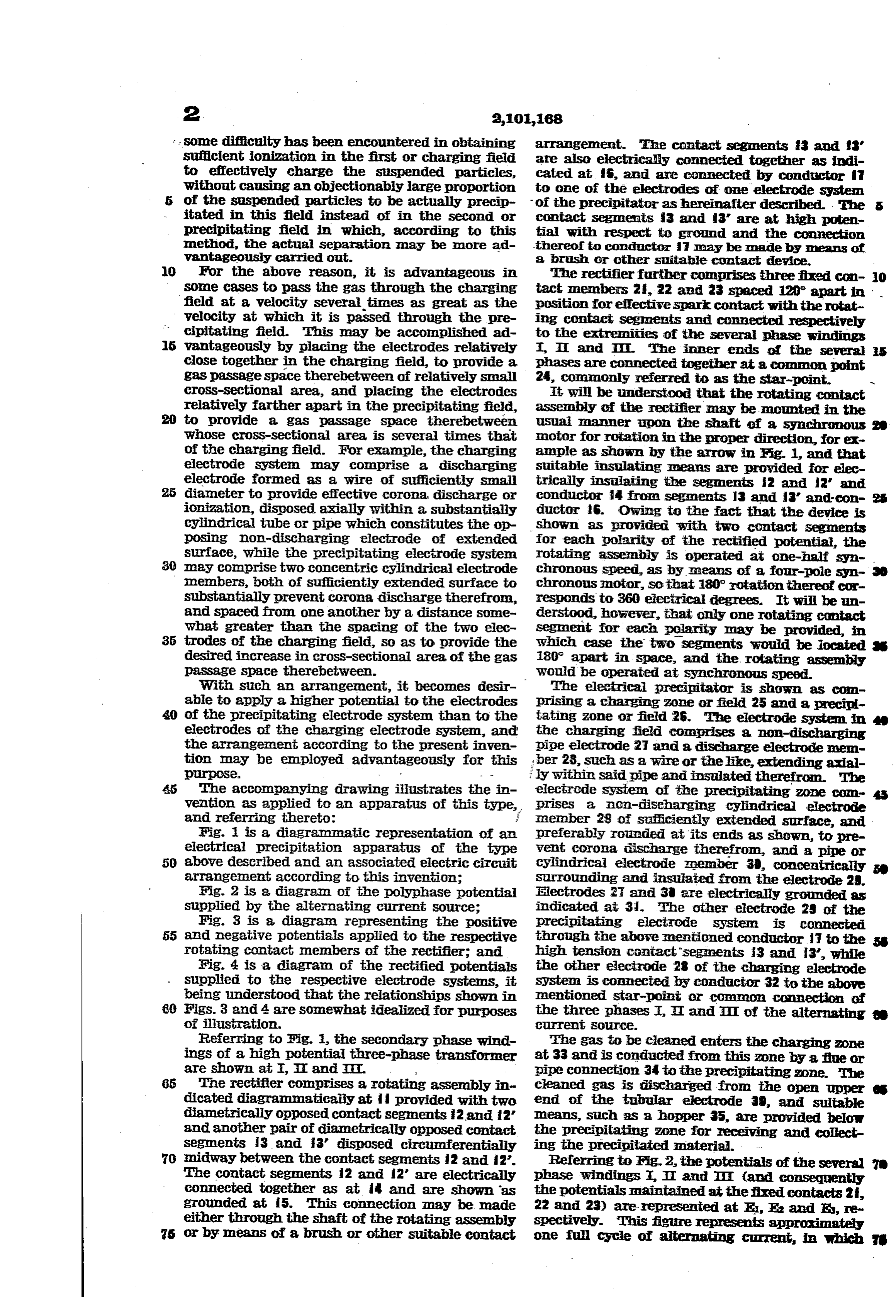
electrical degrees are plotted horizontally, while The fluctuating unidirectional potentials of the the ordinates of the respective curves with respect respective electrode systems are more clearly to the Zero axis O-O represent the difference in shown in Fig. 4, in which curve Ep represents the potential between the respective fixed contacts potential of the electrode 29 with respect to the 2, 22 and 23 and the star-point 24. grounded electrode 30 of the precipitating zone, In the operation of the rectifier, the effective while Ee represents the potential of the electrode 28 with respect to the grounded electrode 27 of contacts between the fixed and rotating contact elements are made and broken at times corre the charging zone, the ground potential line be Sponding Substantially to the points of intersec ing shown at 0'-0". It will be seen that the O tion of the respective curves in Fig. 2. For pur curve Ep has six peaks per cycle of the alternat O pOSes of illustration, it may be assumed that the ing current, while the curve Ec has three peaks high tension electrodes 28 and 29 of the respective per cycle of the alternating current, and that electrode Systems are to be maintained at positive the effective potential in the precipitating Zone is potentials with respect to the grounded electrodes approximately twice the effective potential in the 5 5 27 and 30, respectively. In this case, the rec charging Zone.
tifier is so operated that one or the other of the It will be understood that the spacing between high tension rotating contact segments 3 or 3' electrodes 27 and 28 in the charging zone is such as to provide the desired corona discharge from is Substantially at all times in contact with a fixed contact member which is at the greatest electrode 28, without producing disruptive dis 20 positive potential, while one of the grounded ro charge or arcing, while the spacing between elec 20 tating contact segments 2 or f2' is substantially trodes 29 and 30 is such as to provide a high elec at all times in contact with a fixed contact men trostatic field therebetween without disruptive ber which is at the greatest negative potential, discharge. Due to the difference in the potentials so that, at any instant, the combined potentials ofin these two fields, the electrode spacing in the 25 the two phases corresponding to the two fixed precipitating field may be in the neighborhood contact members so contacted are impressed in of twice that in the charging field, thus obtaining Series upon the respective electrodes 29 and 30 of the above mentioned advantage of a relatively high velocity in the charging field as compared the precipitating electrode system, while the po with tential of the individual phase corresponding to the precipitating field. 30 the fixed contact which is at that time contacted I claim: 30 by one of the grounded rotating contact segments An apparatus for electrical treatment of fluids 2 and 2' is impressed upon the electrodes 27 Comprising two separate electrode systems each and 28 of the charging electrode system, due to Comprising tWO Opposing electrode members the premanent connection of high tension elec Spaced from One another to accommodate flow of trode 28 to the star-point 24 of neutral or inter gas therebetween; a polyphase transformer with 35 mediate potential. Y-Connected secondary phase, windings having a Referring to Fig. 3, the positive potential sup common point connected to one end of each plied to the set of rotating contact segments f3 winding; means electrically connecting one elec and 3’ is represented by the curve E13, which cor trode member of one of said electrode systems to 40 responds in position to the positive peak portions Said common point; and Synchronously operated 40 of the several phase potential curves E1, E2 and E3 mechanical rectifying means associated with the of Fig. 2. Similarly, the negative potential sup other terminals of Said windings, and with the plied to the high tension set of rotating contact other electrode member of said one system, and segments 2 and 2' is represented by the curve also With the two electrodes of the other elec E12, which corresponds to the negative peak por trode System, said rectifying means being oper 45 tions of the several phase potential curves E, Ea able to successively connect the several phases in and E3. Thus, the vertical distance between these dividually to said other electrode member of said two curves, as indicated by the line 38, represents one system and to successively connect different the unidirectional potential supplied to the pre Successive pairs of phases in Series between the 50 cipitating electrodes 29 and 30, while the vertical two electrode members of said other system. distance between curve E12 and the zero axis 0-0, as indicated by the line 39, represents the unidirectional potential supplied to the charging
WALTHER DEUTSCH.
electrodes 2 and 28.
Provenance
- Collection
- Cited prior art
- Original PDF
- patentimages.storage.googleapis.com →
- Filed
- 1937-02-23
- Pages
- 4
- Method
- pdftotext (the PDF's own text layer) + pdftoppm 300dpi page scans
- Source
- Google Patents bibliographic record
- Granted
- 1937-12-07
- Inventors
- Deutsch Walther; International Precipitation Co
- Transcribed from
- patentimages.storage.googleapis.com →