patent · US4973868
Electrical machine with permanent magnet excitation
27 November 1990
Page 1 — bibliographic record
United States Patent (19) 11 Patent Number: 4,973,868 Wust (45) Date of Patent: Nov. 27, 1990 (54) ELECTRICAL MACHINE WITH FOREIGN PATENT DOCUMENTS
PERMANENT MAGNET EXCITATION
(75. Inventor: Bernhard Wust, Giengen, Fed. Rep. X of Germany 3705089 8/1988 Fed. Rep. of Germany ... 310/261 M
73 Assignee: J. M. Voith GmbH, Heidenheim, 00.12408 1/1977 Japan ................................... 310/266 Fed. Rep. of Germany O095091 3/1960 Netherlands ........................ 310/266
(21) Appl. No.: 387,331 Primary Examiner-R. Skudy
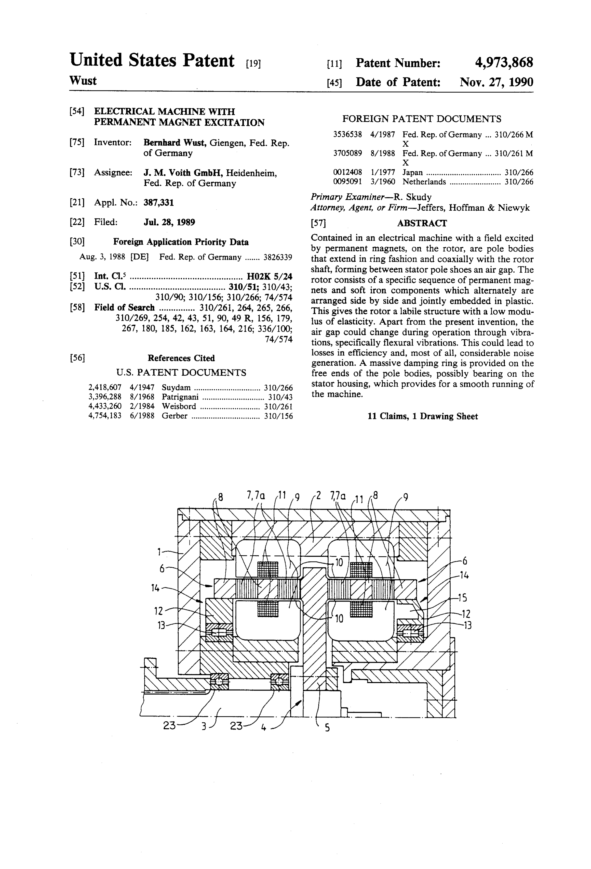
Attorney, Agent, or Firm-Jeffers, Hoffman & Niewyk 22 Filed: Jul. 28, 1989 57 ABSTRACT 30 Foreign Application Priority Data Contained in an electrical machine with a field excited by permanent magnets, on the rotor, are pole bodies
Aug. 3, 1988 DE Fed. Rep. of Germany ....... 3826339 that extend in ring fashion and coaxially with the rotor shaft, forming between stator pole shoes an air gap. The 51) Int. Cl. ............................................... HO2K 5/24 rotor consists of a specific sequence of permanent mag 52 U.S. Cl. ........................................ 310/51; 310/43; nets and soft iron components which alternately are 310/90; 310/156; 310/266; 74/574 arranged side by side and jointly embedded in plastic. 58) Field of Search ............... 310/261, 264, 265, 266, This gives the rotor a labile structure with a low modu 310/269,254, 42, 43, 51, 90, 49 R, 156, 179, lus of elasticity. Apart from the present invention, the 267, 180, 185, 162, 163, 164, 216; 336/100; air gap could change during operation through vibra 74/574 tions, specifically flexural vibrations. This could lead to 56 References Cited losses in efficiency and, most of all, considerable noise generation. A massive damping ring is provided on the
2,418,607 4/1947 Suydam ............................... 310/266 stator housing, which provides for a smooth running of 3,396,288 8/1968 Patrignani............................. 310/43 the machine.
4,433,260 2/1984 Weisbord .... ... 310/26i 4,754, 183 6/1988 Gerber ................................ 310/156 11 Claims, 1 Drawing Sheet
BN-ye NANE
Page 2
Drawing sheet — no readable text.
Page 3
efficiency the prerequisite for designing the electrical
ELECTRICAL MACHINE WITH PERMANENT machine for a higher capacity. MAGNET EXCTATION Further favorable developments of the invention are set forth herein. The massive rings are preferably made
BACKGROUND OF THE INVENTION 5 from fiber-reinforced plastic, making it possible to fas The invention concerns an electrical machine, specif. ten them in a space-saving fashion close to the perma ically a rectifier-energized synchronous machine with nent magnets, without affecting the magnetic flux. A permanent magnet excitation. A machine of this cate particular advantage lies in the fact that the rings may gory is known from the unpublished German Patent 10 extend radially inward toward the rotor shaft, making it Disclosure No. 37 05089.3. possible, additionally, to provide a mounting that is The peculiarity of this design is constituted by the arranged in the stator housing, specifically by means of fact that the rotor comprises essentially a central disk to an antifriction bearing. The result is a further solidifica which, in the area of the outer circumference and on tion of the rotor in the sense of improving the smooth both sides, a ring-shaped pole body structure that is 15 ness of running. The ring may in a partial area be so coaxial with the rotor shaft is attached. This pole body designed that it will yield slightly at least in radial direc structure consists of a defined sequence of permanent tion. This will equalize distortions in the housing or in magnets and soft iron components which alternately are the rotor, without affecting the air gaps. Additionally, it arranged side by side and in peripheral direction. is also possible to enlarge the rings radially, inwardly The permanent magnets and soft iron components are and outwardly, up into the area of the pole shoes. This jointly embedded in plastic, true to measure and in 20 makes it possible to forego under certain conditions an ring-shaped fashion, and as well fastened on the central additional mounting or support in the stator housing, disk in axial direction. The central disk itself consists because the ring enveloping the ends of the pole bodies preferably of fiber-reinforced plastic. The free end of is quite rigid itself.
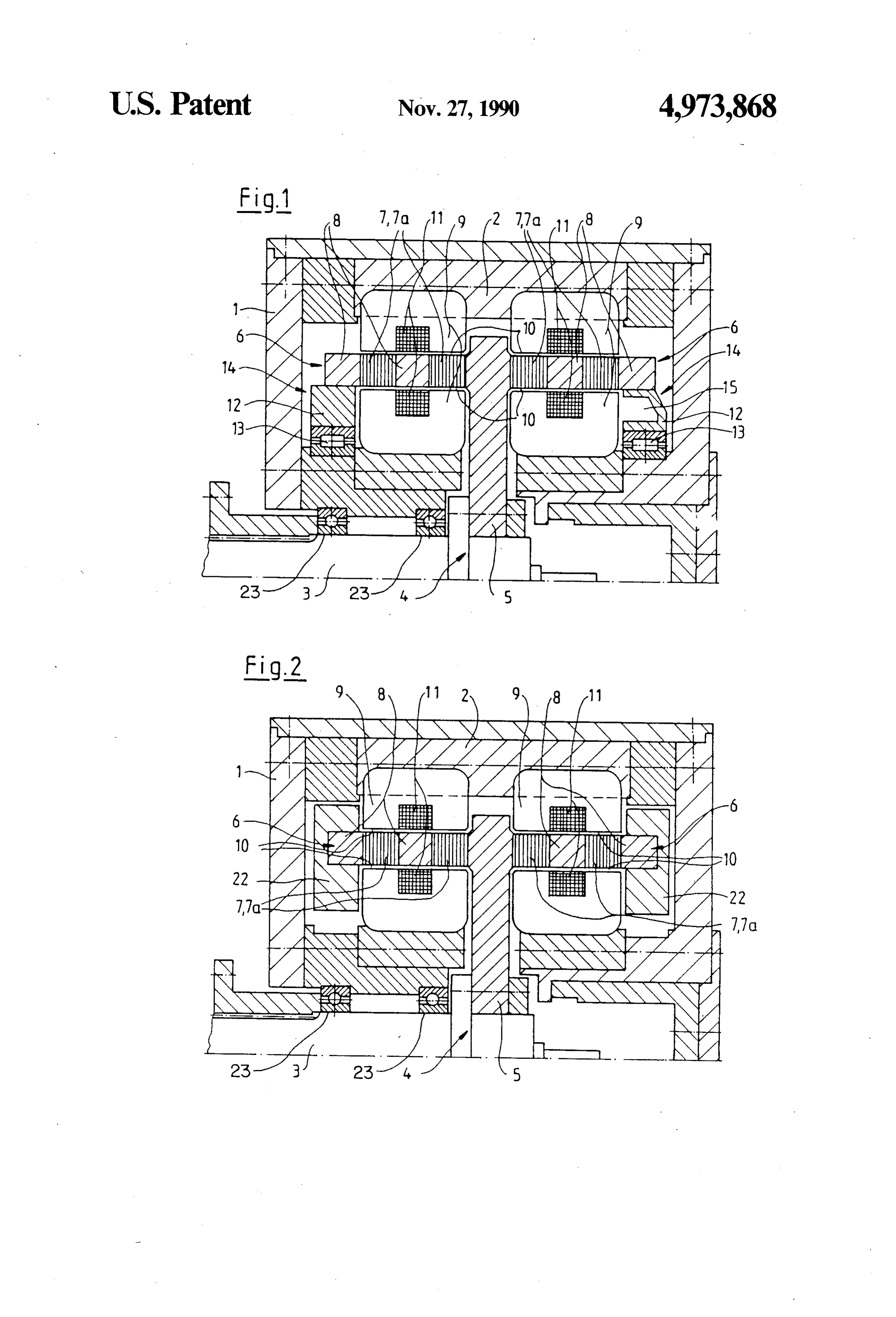
each pole body structure, away from the disk, features a cover plate which consists as well of plastic. 25 BRIEF DESCRIPTION OF THE DRAWING Arranged around the inner and outer circumference Two embodiments of the invention will be more fully of the pole body structure are pole elements which are explained hereafter with the aid of the drawing. integral parts of the stator of the machine and feature inside coils through which flows current. Directed section of ashows
motor schematically a partial longitudinal with a supported rotor; and toward the pole body structure of the rotor are open 30
FIG. 2 shows schematically a partial longitudinal pole shoes which, except for a slight air gap, extend up section the same as FIG. 1, where the rotor features a to the rotor.
The magnetic flux properties demand that the rotor, massive reinforcement ring without bearing. in its supporting mechanical components, be made ex DESCRIPTION OF THE PREFERRED tensively from plastic. The pole body is thus given an 35 EMBODIMENTS inhomogeneous structure where, for one, the metallic permanent magnets and soft iron components are em Marked 1 in FIG. 1 is a stator housing in which a bedded with their mass in plastic which, on the other rotor shaft 3 is rotatably mounted by means of antifric hand, however, has a modulus of elasticity that is about tion bearing 23. Fastened on this rotor shaft, on a flange, ten times as low as that of steel. Consequently, the rotor is a rotor 4. The latter comprises a central disk 5 on is a labile component which operationally tends to any which border, on its outer circumference, ring-shaped type of vibrations, specifically flexural vibrations. This, pole bodies 6 that are coaxial with the rotor shaft 3. The in turn, leads to unequal air gaps between the pole bod frominner design of the rotor 4 corresponds to that known ies and pole shoes. Unfavorable in this context are not the German Patent Disclosure No. 37 05089. The only air gap differences between the right hand and left 45 pole bodies 6 consist of a specific sequence of perma hand side but specifically between the air gaps on the nent magnets 7 and soft iron components 7a which are inner and outer circumference of the pole bodies. The arranged alternately side by side and in peripheral di result is a disturbed flux line pattern during rotation, rection, and which jointly with ring-shaped elements 8 which expresses itself in a considerable noise generation are embedded in plastic between and beside the perma and poor efficiency. Therefore, machines of this type 50 ment magnets.
cannot be manufactured yet for higher output and/or Radially inward of and outward of the pole bodies 6 speed of rotation. there are pole shoes 9 arranged on the stator housing 1 The problem underlying the invention is to so design in such a way that relative to the pole bodies 6, at least an electrical machine according to the categorial defini in the area of the permanent magnets 7, radial air gaps tion that the run performance of the rotor will be im 55 10 will be created. The pole shoes 9 are distributed proved and the capacity of the machine can be in across the entire circumference and permeated by wind creased. ings 11. They form a stator 2 of the motor that is ar SUMMARY OF THE INVENTION ranged, fixed, in the stator housing 1. Radially inward of the outermost ring-shaped element 8 opposite the
The problem stated above is solved through the fea central disk 5, a massive ring 12, in the form of a round tures of the present invention. The invention provides central disk of fiber-reinforced plastic, is arranged. This for arrangement of massive rings on the free ends of the ring 12 is supported on the stator housing 1 by means of ring-shaped pole bodies, away from the central disk. a sealed bearing 13 enclosed by ring 12. The right hand These disks serve the form stabilization of the pole part of FIG. 1 illustrates how the massive ring 12 can be bodies during operation and assure consistent roundness 65 provided, in a partial area 14, with recesses 15. This and, thus, constant air gaps between the pole shoes and creates a slight radial and/or axial flexibility between the pole bodies of the rotor. This reduces the noise the rotor and the stator housing 1, keeping the pole generation and provides through improvement of the bodies free from an harmful constraining forces. The
Page 4
support effect provided by the bearing 13 is upheld envelop the pole body on the entire inner and outer nonetheless. circumference thereof, except for the free axial end In FIG. 2, identical parts have been tagged using faces thereof;
identical reference symbols. The illustrated motor cor said ring-shaped pole body and said ring-shaped pole responds in its design with that of FIG. 1. On the ends shoes defining therebetween annular air gaps; and of the pole bodies 6 opposite the central disk there is a pair of massive rings for stabilization of the rotor located a massive ring 22 each that extends both radially against running vibrations, each fastened on a free inward and radially outward of the central disk, thus end face of the ring-shaped pole body. representing a rigid component. Depending on the size of the motor or the housing design or other design 10 each massive ring motor 2. An electrical
according to claim 1, in which composed of plastic.
conditions, such provision of a reinforcing ring makes it possible to forego a mounting or support on the gear each massive ring is supported ontotheclaim 3. An electrical motor according 1, in which stator housing housing 1.
It goes without saying that the rings 12 and 22 ac through a bearing.
cording to FIGS. 1 and 2, respectively, can for damping each massive ringmotor 15 4. An electrical according to claim 2, in which and reinforcement of the pole bodies be inserted and through a bearing. is supported on the stator housing fastened only toward the end of the assembly process. 5. An electrical motor according to claim 3, in which Consequently, the stator housing requires a split design.
Details in that respect are not illustrated specifically. the massive ring extends radially inward of said ring What is claimed is: 20 shaped pole body.
1. An electrical motor with a field excited by perma the6.bearingAn electrical motor according to claim 3, in which is an antifriction bearing which is enclosed nent magnets comprising:
a stator housing; by the massive ring.
a rotor including a rotor shaft mounted in said stator 7. An electrical motor according to claim 5, in which housing and having a round central disk of fiber 25 the bearing is an antifriction bearing which is enclosed reinforced plastic extending substantially radially by the massive ring.
from and fixed to said rotor shaft for rotation there 8. An electrical motor according to claim 5, in which with: the massive ring is, at least in a partial area between the a ring-shaped pole body coaxial with the rotor shaft pole body and the bearing, flexible at least radially. and connected to the outer periphery of the central 30 9. An electrical motor according to claim 6, in which disk, said ring-shaped pole body extending axially the massive ring is, at least in a partial area between the in opposite directions from the central disk and pole body and the bearing, flexible at least radially. having an inner circumferential surface, an outer 10. An electrical motor according to claim 1, in circumferential surface and free axial end faces, which the massive ring extends radially outward and said ring-shaped pole body including alternately 35 inward from the pole body toward the area of the pole arranged permanent magnets and soft iron compo shoes.
nents embedded in plastic and connected with each 11. An electrical motor according to claim 2, in other thereby; which the massive ring extends radially outward and ring-shaped pole shoes having windings and being inward from the pole body toward the area of the pole fixed to said stator housing and arranged radially shoes.
inward of and outward of the pole body so as to k k xx k
Provenance
- Collection
- Cited prior art
- Original PDF
- patentimages.storage.googleapis.com →
- Filed
- 1989-07-28
- Pages
- 4
- Method
- pdftotext (the PDF's own text layer) + pdftoppm 300dpi page scans
- Source
- Google Patents bibliographic record
- Granted
- 1990-11-27
- Inventors
- Bernhard Wust; JM Voith GmbH
- Transcribed from
- patentimages.storage.googleapis.com →