patent · US20110185990A1
System and method for improving combustion using an electrolysis fuel cell
4 August 2011
Page 1 — bibliographic record
(19) United States (12) Patent Application Publication (10) Pub. No.: US 2011/0185990 A1
Inwald (43) Pub. Date: Aug. 4, 2011 (54) SYSTEMAND METHOD FOR IMPROVING Publication Classification
COMBUSTION USING ANELECTROLYSIS
FUEL CELL (51) Int. Cl.
(76) Inventor: David Inwald, Franklin, MI (US) C25B 9/00 (2006.01)
(21) Appl. No.: 13/122,470 (52) U.S. Cl. .............................. 123/3; 204/242: 205/628 (22) PCT Fled: Oct. 2, 2009 (57) ABSTRACT A system for improving combustion including electrolysis
means for producing and storing hydrogen and oxygen gases
S371 (c)(1), operatively connected to injection means for injecting the (2), (4) Date: Apr. 4, 2011 hydrogen and oxygen gas into a combustion device. A hydro gen enrichment system. A method of improving combustion
Related U.S. Application Data by producing and storing hydrogen and oxygen gases, inject ing the hydrogen and oxygen gases into a combustion device, (60) Provisional application No. 61/102,098, filed on Oct. and performing combustion. A method of distributing current 2, 2008. in an electrolysis system.
Page 2
Drawing sheet — no readable text.
Page 3
Drawing sheet — no readable text.
Page 4
Drawing sheet — no readable text.
Page 5
Drawing sheet — no readable text.
Page 6
Drawing sheet — no readable text.
Page 7
Drawing sheet — no readable text.
Page 8
Drawing sheet — no readable text.
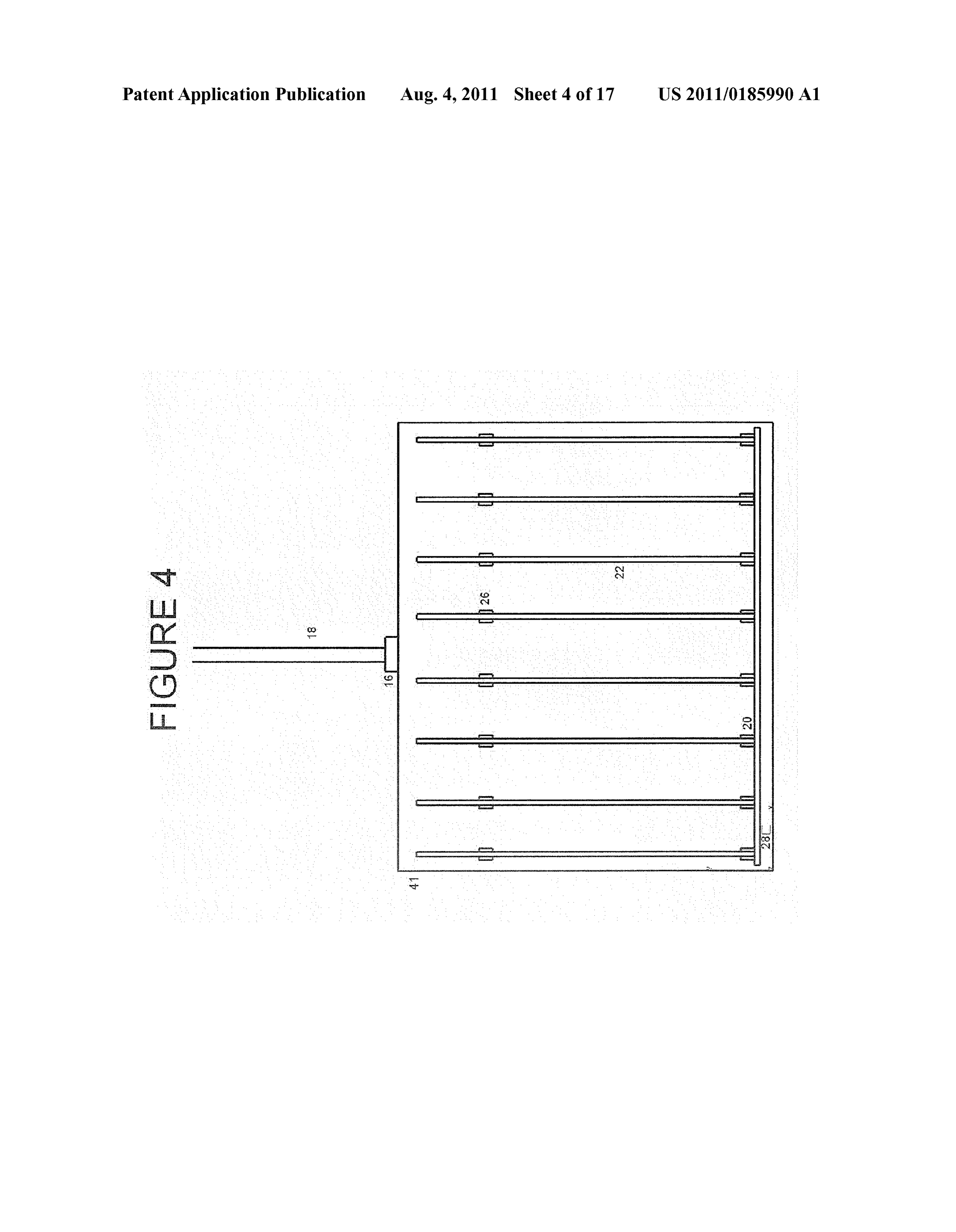
Page 9
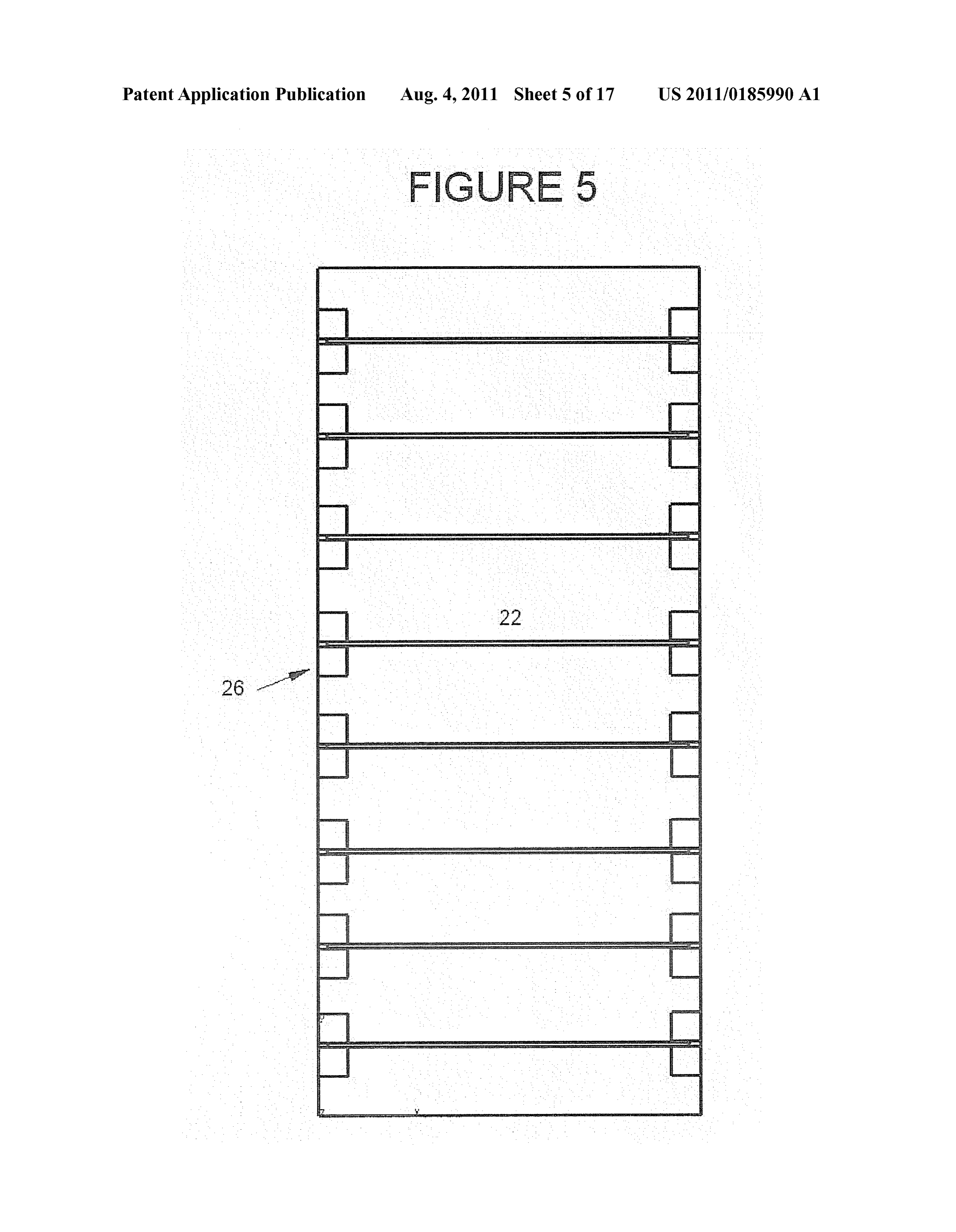
Drawing sheet — no readable text.
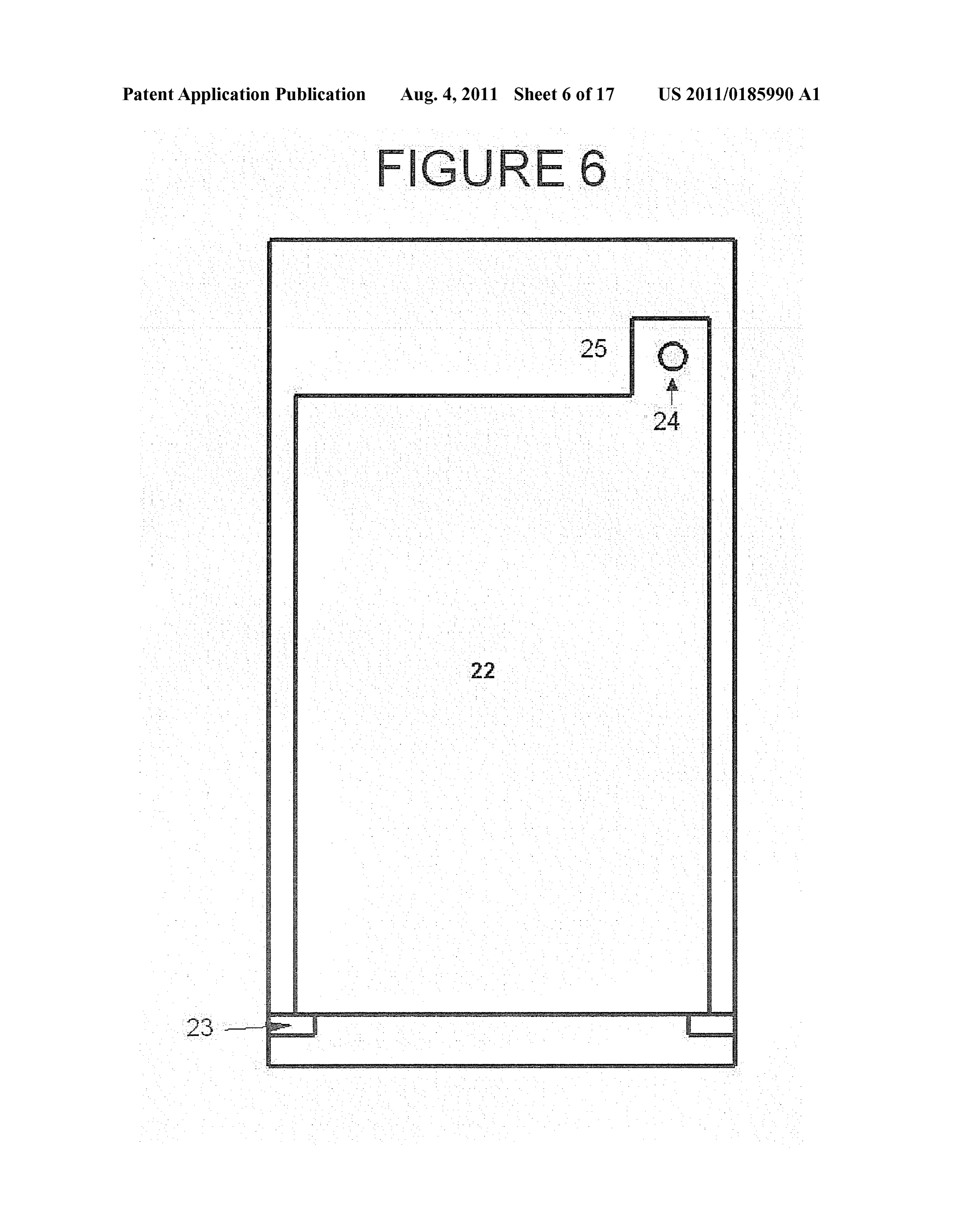
Page 10
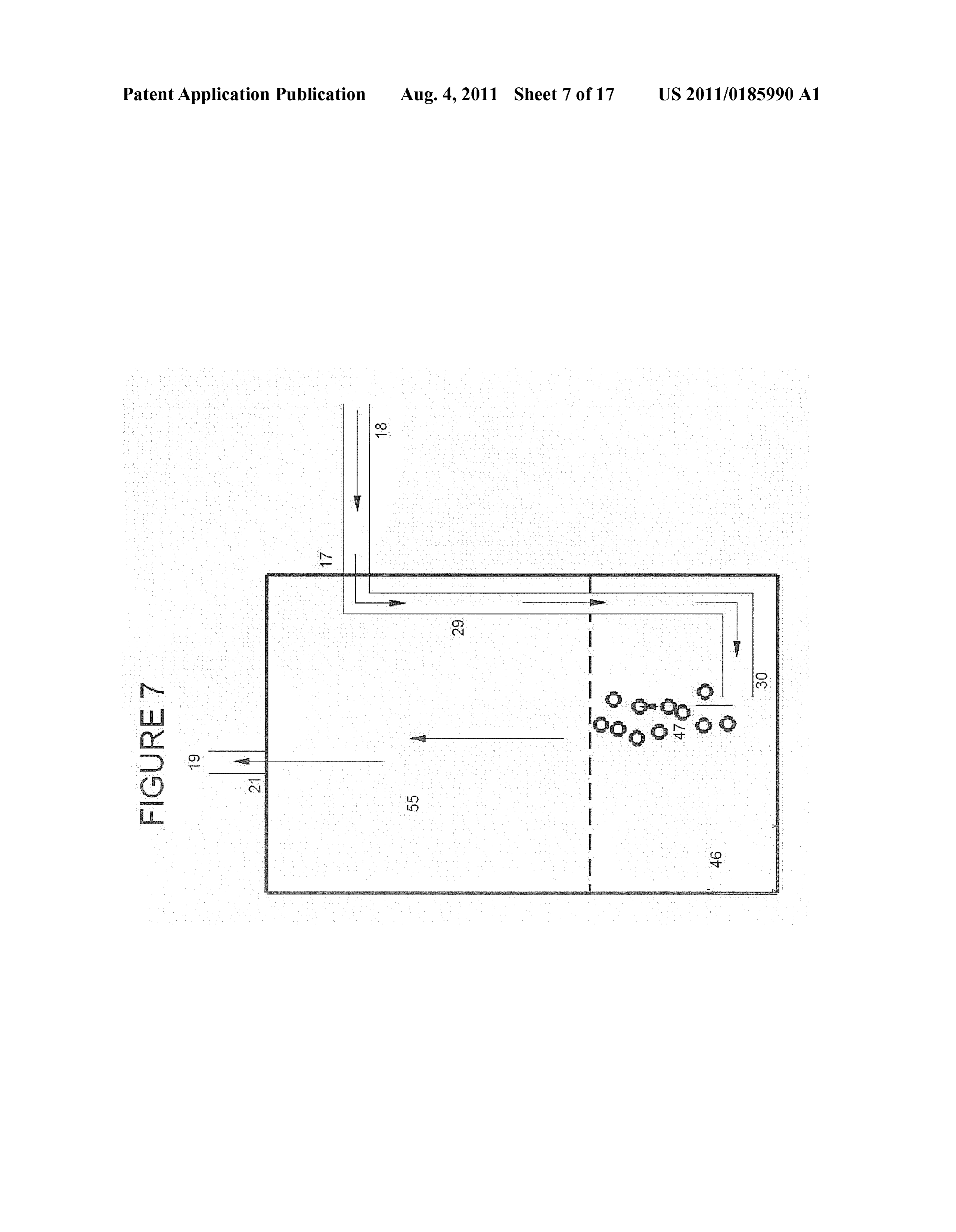
Drawing sheet — no readable text.
Page 11
Drawing sheet — no readable text.
Page 12
Drawing sheet — no readable text.
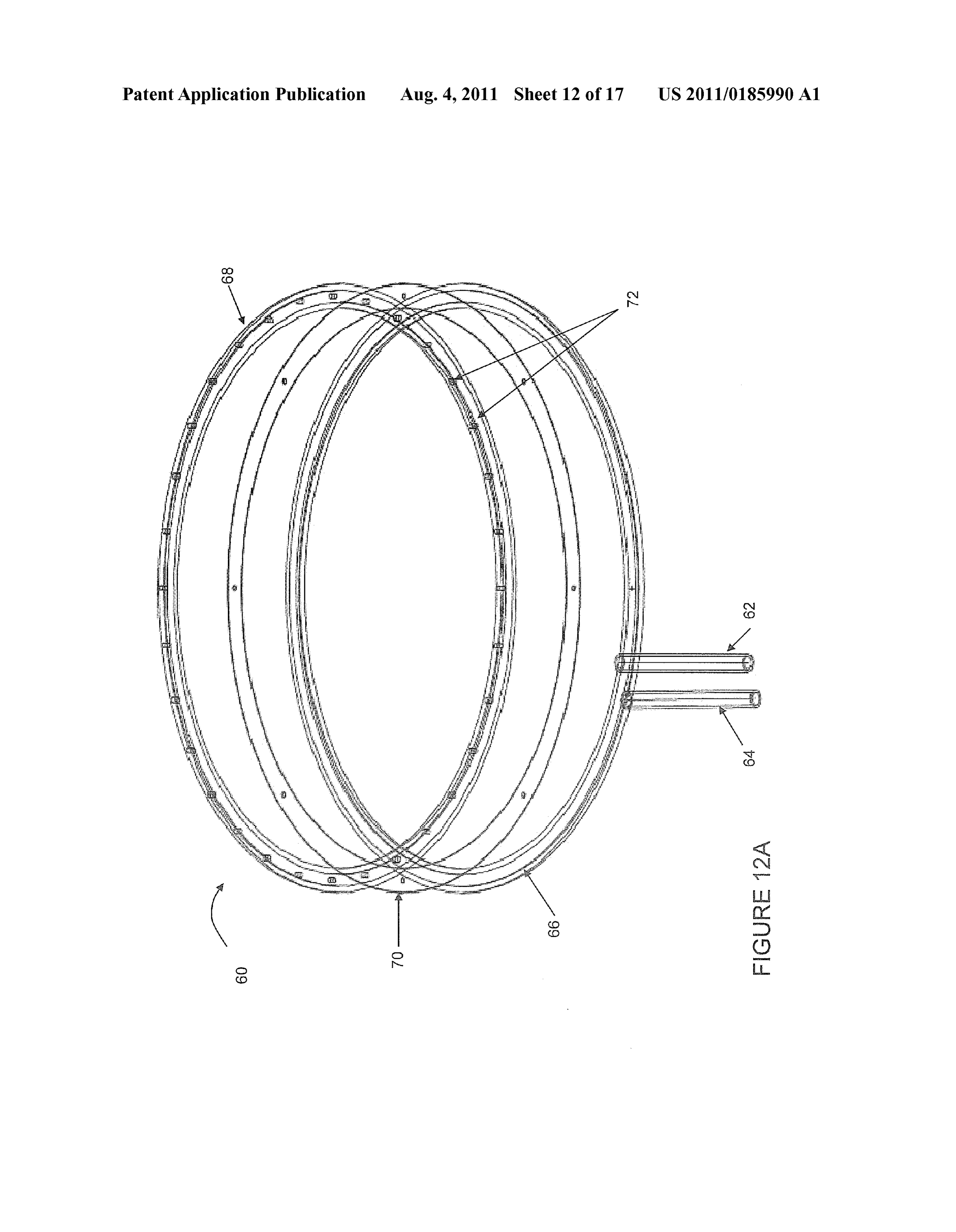
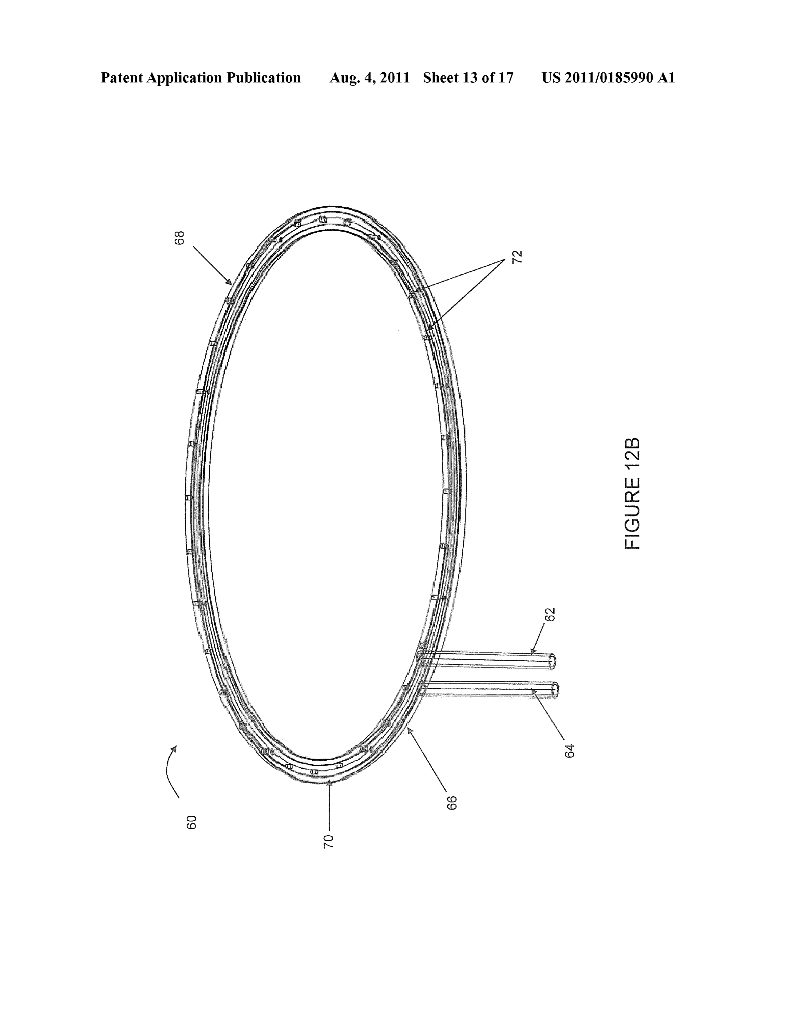
Page 13
Drawing sheet — no readable text.
Page 14
Drawing sheet — no readable text.
Page 15
Drawing sheet — no readable text.
Page 16
Drawing sheet — no readable text.
Page 17
Drawing sheet — no readable text.
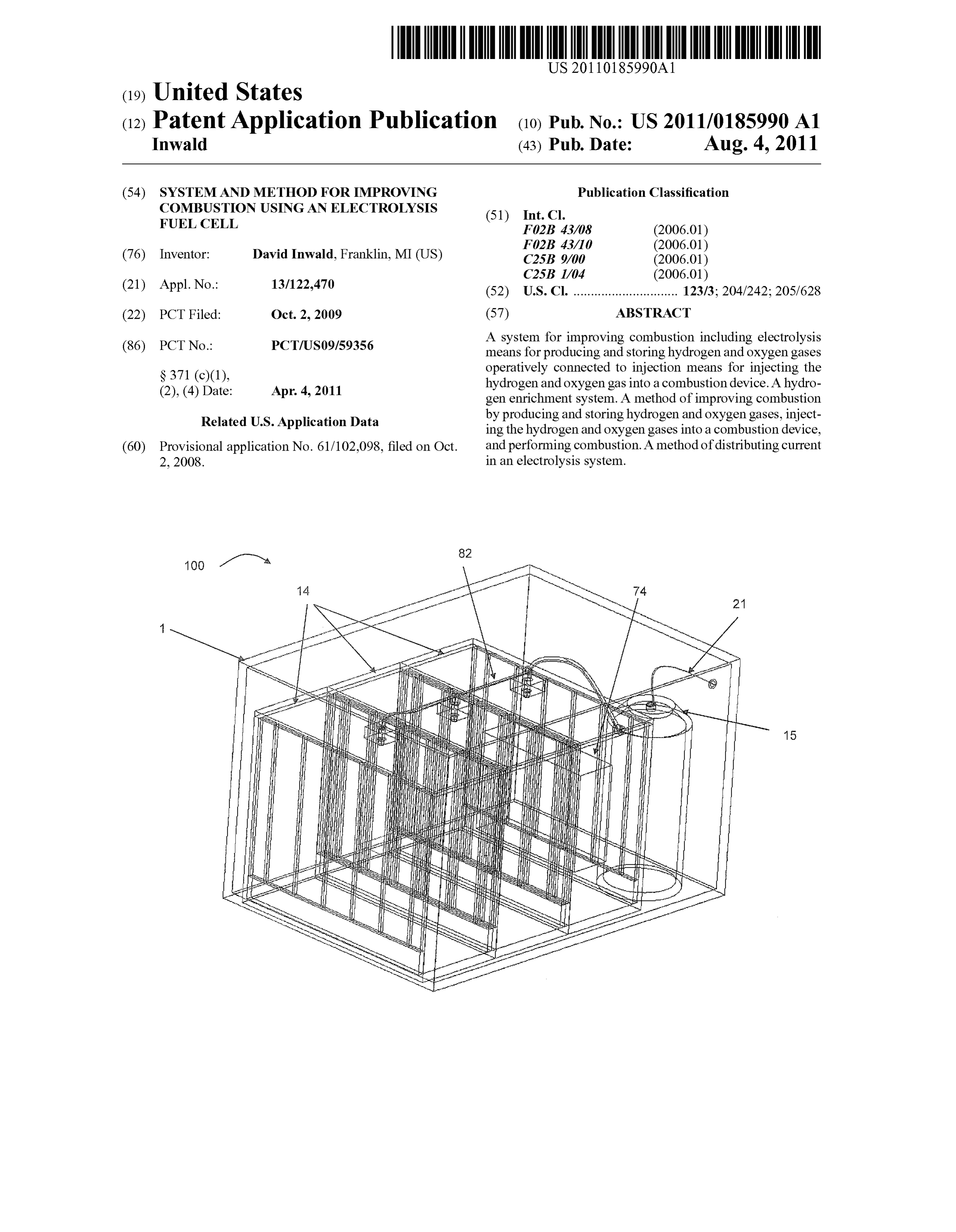
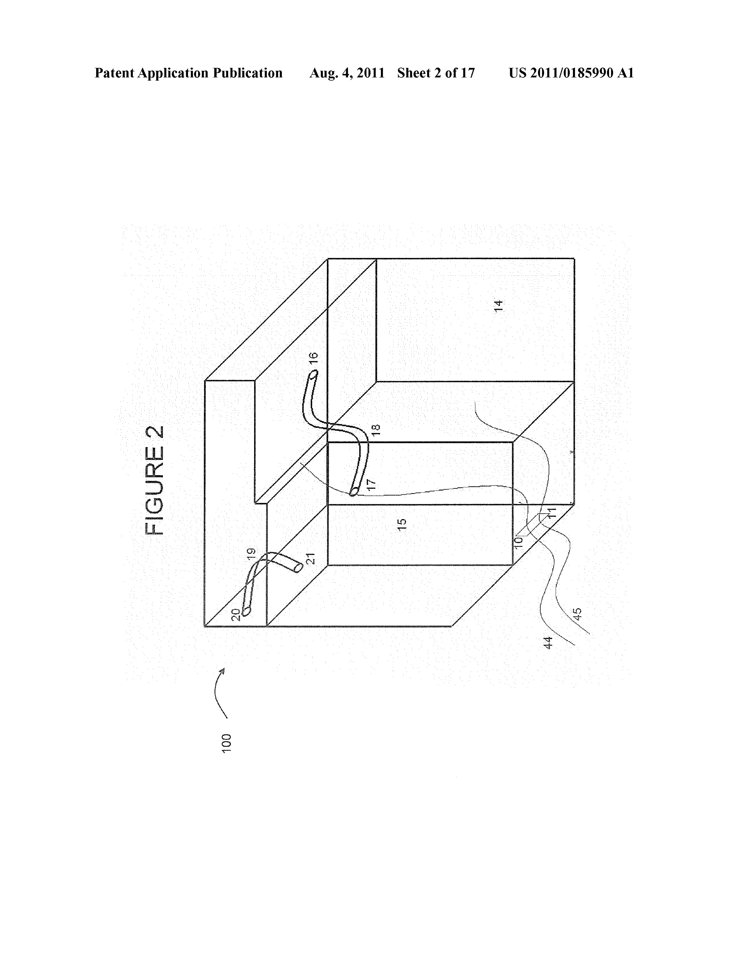
Page 18
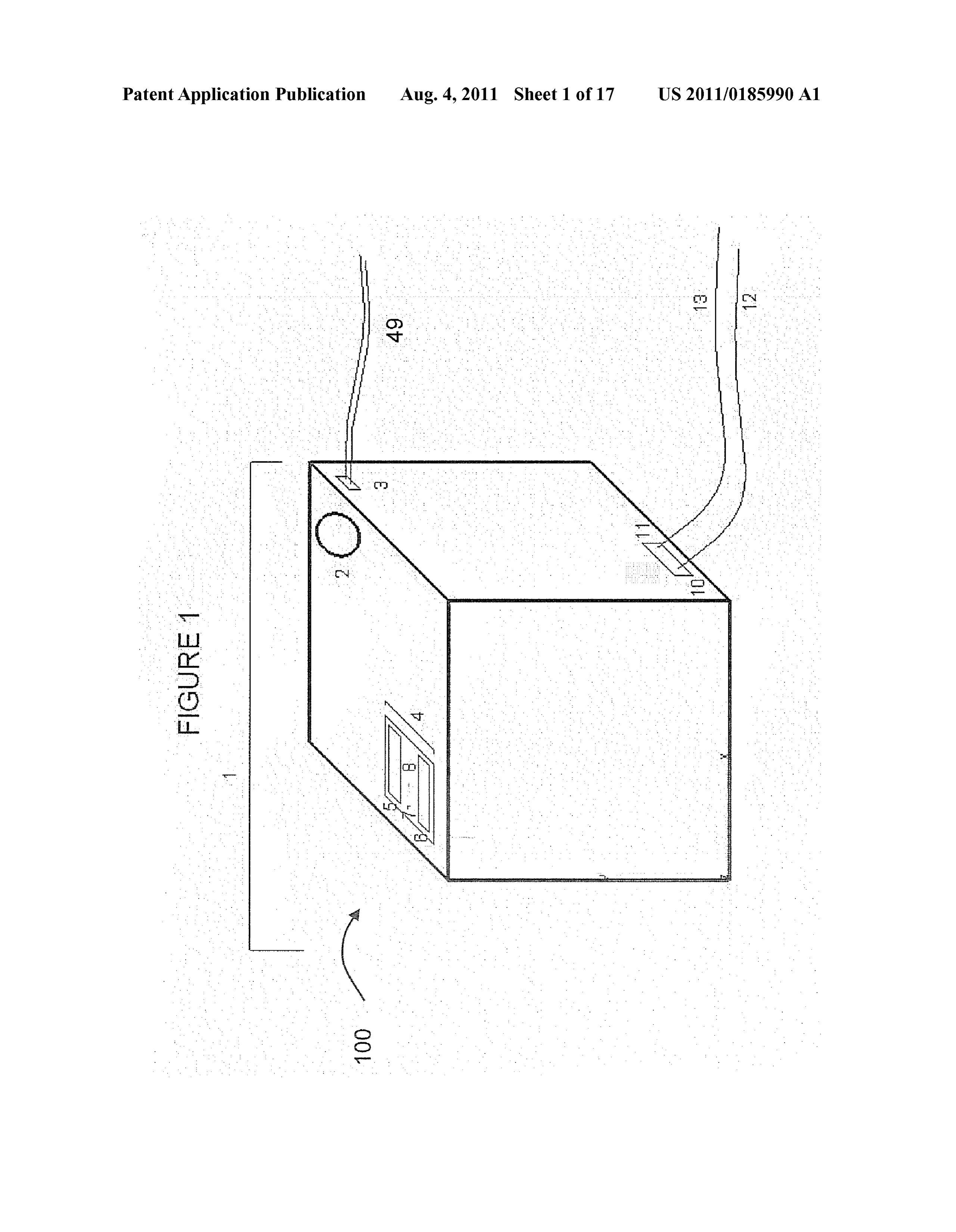
Drawing sheet — no readable text.
Page 19
US 2011/O 185990 A1 Aug. 4, 2011
SYSTEMAND METHOD FOR IMPROVING 0008. The burning temperature of the gas created proves to COMBUSTION USING ANELECTROLYSIS be an effective way to calculate the energy content of the FUEL CELL gaseous Substance. The burning temperature represents the energy content in a given amount of gas. The burning tem
BACKGROUND OF THE INVENTION perature of pure hydrogen is 2318°C. Oxygenburns slightly 0001 1. Technical Field higher attemperatures climbing past 3000°C. The gases at a 0002 The present invention generally relates to the field of 2:1 ratio of hydrogen to oxygen, however, burn at around combustion engines. More specifically, the present invention 5000° C.—much greater energy content than either of the relates to a system and method for using an electrolysis fuel gases alone. This increased amount of energy is precisely why cell to enhance combustion. the effect of adding larger quantities of oxygen to hydrogen 0003 2. Background Art aids the combustion process. Although burning temperatures 0004 Utilizing a hydrogen fuel injection system to of 5000° C. can seem too hot for any common application, improve power and efficiency of internal combustion engines temperatures only reach Such levels when the gases are burnt
has been attempted in the past, however prior methods of fuel injection have proved economically disadvantageous, inef 0009. In order to ensure an even 2:1 production of hydro fective, and provide no significant environmental reward. gen to oxygen, a true catalyst, one which affects neither the 0005 Basic electrolysis involves two electrodes, the product nor the reactant, must be used. The most readily anode and the cathode, Submerged in an aqueous solution available electrolyte, sodium chloride (NaCl) fits this profile. with an electrolyte. The electrolyte theoretically acts as a Sodium chloride (NaCl), common table salt, is an electrolyte catalyst in the electrochemical reaction as it provides a that is neither an acid nor base, and will therefore not affect medium for the electrons of the direct current to flow through the atoms of oxygen once they are split from their hydrogen the water. In actuality, however, very few electrolytes are true counterparts.
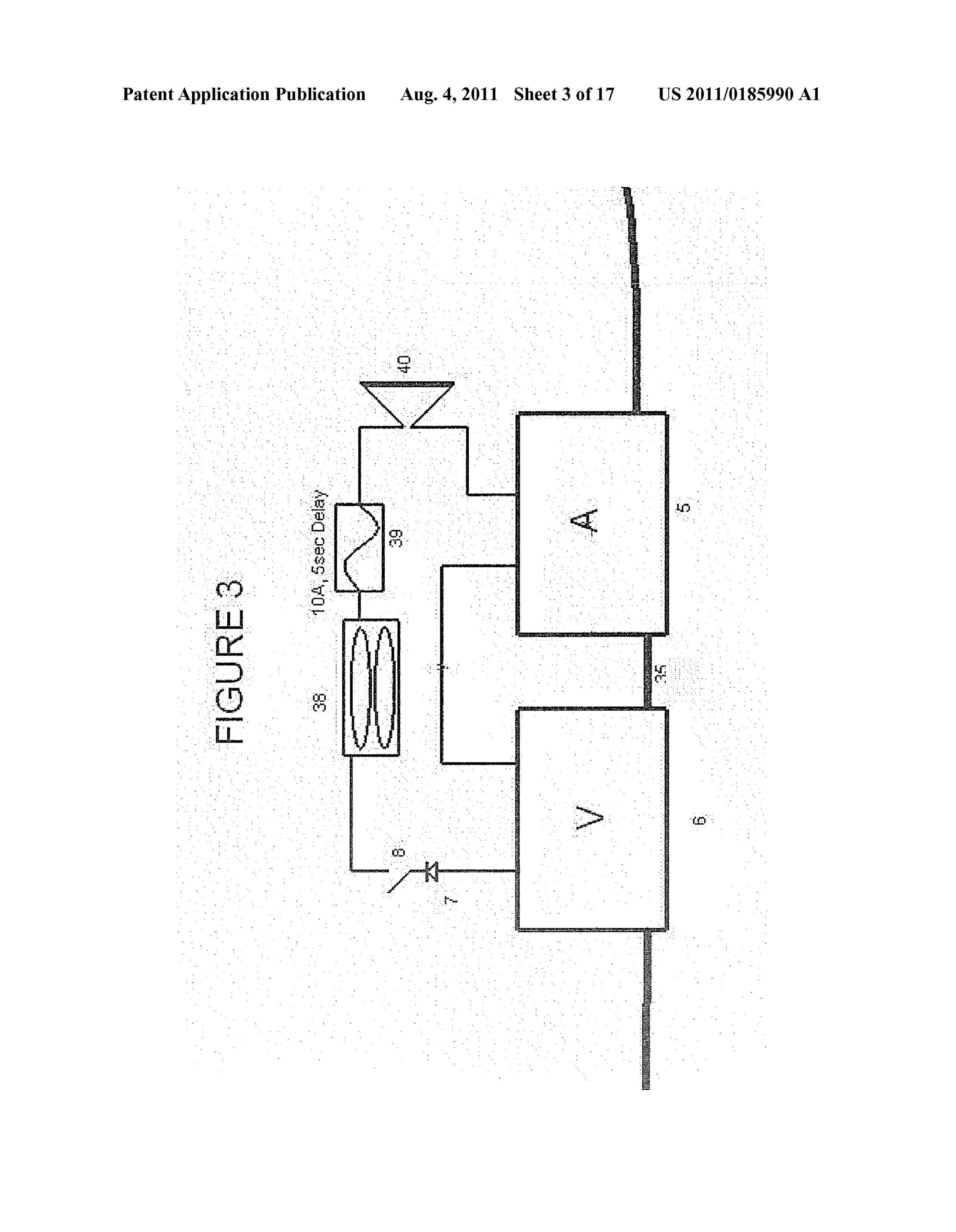
catalysts in electrolysis applications. The definition of a cata 0010. The environmental impact of the adoption of a lyst is a chemical Substance that increases the rate of a chemi hydrogen and oxygen fuel injection system is significant. The cal reaction without further altering the reactants or the prod concept behind fuel injection systems is to more completely uctS. combust the given hydrocarbons. In automobiles, for 0006. The most common electrolytes for hydrogen pro example, gasoline is the hydrocarbon. When the gasoline ducing fuel cells are the common bases sodium hydroxide goes through the current internal combustion system, a cer (NaOH) and potassiumhydroxide (KOH). Both of these elec tain amount of the hydrocarbon fuel is left over because of trolytes are strong bases, meaning that their ionic bonds dis incomplete combustion. There are two main reasons incom sociate when dissolved in water. The electrolysis splits the plete combustion exists. The first source of incomplete com bonds between the hydrogen and oxygen atoms in water. As bustion is the lack of overall heat in the burning of the fuel. Soon as the oxygen molecules are separated from the hydro Certain fuels, gasoline for example, require a higher burning gen in the water molecule some of the oxygen molecules then temperature than is provided in the combustion chamber of partially bond with the electropositive ions (metals). When the internal combustion engine. Hydrogen and oxygen gases the oxygen reacts with these ions, they go through a process have a higher burning temperature, and therefore raise the which ultimately results in the productions of more water temperature in the combustion chamber for the gasoline. molecules, but limits the amount of oxygen produced in a Because of this, the gasoline burns more completely. gaseous form. Theoretically, with an ideal catalyst, for each 0011. The second source of incomplete combustion is two units of hydrogen gas produced, one unit of oxygen gas found in the lack of oxygen in the combustion chamber. should be produced. By using bases as electrolytes (NaOH, Although the chemical composition of fuel is effected by KOH, etc.), the electrolytic cell increases this ratio of hydro specific crude oil source, the average amount of oxygen can gen to oxygen from 3:1 to 4:1, instead of 2:1. be calculated for a given amount of gasoline. According to 0007 Hydrogen is known to be more explosive in a com calculations, 7.0032x10" grams of oxygen are needed per bustion reaction than oxygen; however, it is a false assump gram of gasoline. This means that at standard temperature and tion to take for granted that in an internal or external combus pressure, 15.6872 mL of oxygen is needed. It can be assumed tion system that the more hydrogen the better. The present that at sea level that 20.95% of the atmospheric gases is pure invention utilizes hydrogen and oxygen gas in a 2:1 ratio to oxygen. Therefore, when an internal combustion engine is improve efficiency for any type of combustion, and preferably burning a given load of one gram, it is required to have 74.88 direct combustion. In combustion, hydrogen has very unique mL of atmospheric gases. This number, however, is often properties, with the most important being its wide flamma times not reached because there is insufficient air in the com bility range. At standard temperature and pressure (1 ATM, bustion chamber of the cylinder. This yield yields an incom 273.15 degrees Kelvin), a mixture of hydrogen and air will plete combustion of fuel.
burn when there is as little as 4 percent hydrogen or as much 0012 Environmentally, this means that more carbon mon as 75 percent hydrogen in the mixture. When hydrogen and oxide, Sulfur hexafluoride, and other Such gases are released oxygen gases are mixed together, the flammability range into the environment. In addition, more vaporized gasoline is increases further; from as little as 3% to near 99%. Injection released into the environment withoutgoing through the com systems are commonly scrutinized because it is said that the bustion process, which is the same thing as dumping out a electrolysis method of hydrogen production yields a non given percentage of gasoline from each tank of gas into the Sufficient amount of gas to make any difference in combus atmosphere.
tion. The properties of hydrogen and oxygen gases in the 0013 U.S. Pat. No. 6,257,175 to Mosher et al. discloses an mixture as discussed above prove this to be incorrect; because electrolysis unit that generates hydrogen gas and oxygen gas the gases will aide in combustion even when a mere 3% of the from water and an electrolyte. Mosher attempts to improve gases are mixed with atmospheric gases. the unit's safety by attempting to collect and isolate the gen
Page 20
US 2011/O 185990 A1 Aug. 4, 2011
erated hydrogen and oxygen gasses. However, additional 0018 Thus, there remains a significant need for an elec safety concerns arise upon implementation of Mosher's con trolysis unit for enhancing combustion which overcomes the cept. Injecting pure hydrogen gas into the engine cylinder (as various shortcomings and disadvantages found in the prior Suggested by Mosher) can lead to the hydrogen igniting pre art.
maturely, creating an unstable and unsafe situation, known by the automotive community as "knocking, which exists when SUMMARY OF THE INVENTION any fuel ignites prematurely. Furthermore, in Mosher the 0019. The present invention provides for a system for method of injection calls for a unique installation of addi improving combustion including an electrolysis mechanism tional parts in the intake manifold of the car, which raises for producing and storing hydrogen and oxygen gases opera questions about the purpose of the invention. tively connected to an injection mechanism for injecting the 0014. It is known that vaporized fuel injection systems are hydrogen and oxygen gas into a combustion device. beneficial to improved efficiency for a plethora of applica 0020. The present invention also provides for a hydrogen tions; however, it is anticipated that newer technologies will enrichment system including at least one production mecha completely eliminate the need for fossil fuels. As such, fuel nism for producing hydrogen and oxygen operatively con injection systems that require a great deal of engine modifi nected to a pressure-equalizing unit within an enclosure, and cations will prove unworthy to consumers. If the cost to an electronic control mechanism for controlling an amount of purchase an injection system is too great to the consumer, the hydrogen and oxygen produced.
technology will likely be ignored until the next alternative 0021. The present invention provides for a method of energies are developed further and made available to consum improving combustion by producing and storing hydrogen ers. Therefore, it is a priority for currentfuel injection systems and oxygen gases, injecting the hydrogen and oxygen gases to be simple enough to be reliable, be easy to install and into a combustion device, and performing combustion. remove without engine modifications, and be cost effective 0022. The present invention further provides for a method immediately for the average consumer. Mosher et al. provides of distributing current in an electrolysis system by routing a system that requires major modifications to the engine, power from a current source with an electronic control sys which defeats a significant purpose of Such an invention— tem, dedicating electricity for external demands, dedicating namely, economic savings to the consumer. The means of the electricity for hydrogen production, controlling the propor present invention is designed for easy implementation to pro tion of hydrogen and oxygen produced, Supplying electricity vide a path for the alternative energies of the future. for production of hydrogen and oxygen, producing hydrogen 0015 U.S. Pat. No. 6,311,648 to Larocque discloses a and oxygen at an output chosen from the group consisting of hydrogen-oxygen/hydrocarbon fuel system for enhancing the fixed and variable, storing the hydrogen and oxygen, and efficiency of an internal combustion engine. One of the sig feeding back results to the electronic control system. nificant shortcomings of the Larocque system is that it relies upon gravity to refill the water level inside the electrolytic DESCRIPTION OF THE DRAWINGS chamber. In real-world applications involving inclines and turbulent road conditions, it is likely that unintended water 0023. Other advantages of the present invention are will be added to the electrolytic chamber. Since maintaining readily appreciated as the same becomes better understood by a precise amount of electrolyte in the system is critical, reference to the following detailed description, when consid Larocque's system is not well Suited for real-world applica ered in connection with the accompanying drawings wherein: tions. Furthermore, Larocque does not account for the chang 0024 FIG. 1 is a diagram representing the external archi ing weather conditions which face real-world drivers which tecture of the collective enclosure of the present invention; could significantly affect the performance of the system. 0025 FIG. 2 is a diagram representing the major compo 0016 U.S. Pat. No. 7,143,722 to Ross discloses an elec nents within FIG. 1;
trolysis unit for Supplying gaseous fuel additives to enhance 0026 FIG. 3 is a schematic diagram representing the combustion in a combustion engine. However, Ross identifies monitoring system, on/off switch as well as main power indi potassium hydroxide (KOH) as the required electrolyte in the cation LED;
system. As described, the use of KOH in Ross’ system pre 0027 FIG. 4 is a diagram of the hydrogen and oxygen sents several design defects and problems, among them: the production unit with a frontal view focusing on the construc severely corrosive nature of high concentrations of KOH, the tion of the plates;
inefficiency and wasted electronic resistance that result when 0028 FIG. 5 is a diagram of the hydrogen and oxygen using KOH, and the resulting KO byproduct produced by the production unit with a lateral view: system which is an extremely potent and toxic Substance. 0029 FIG. 6 is a diagram of the hydrogen and oxygen Furthermore, the injection system described by Ross will production unit with an overhead view: likely require a significant amount of time before being able 0030 FIG. 7 is a diagram representing the vapor pressure to run at an adequate output, a situation which is impractical equalizer and storage unit;
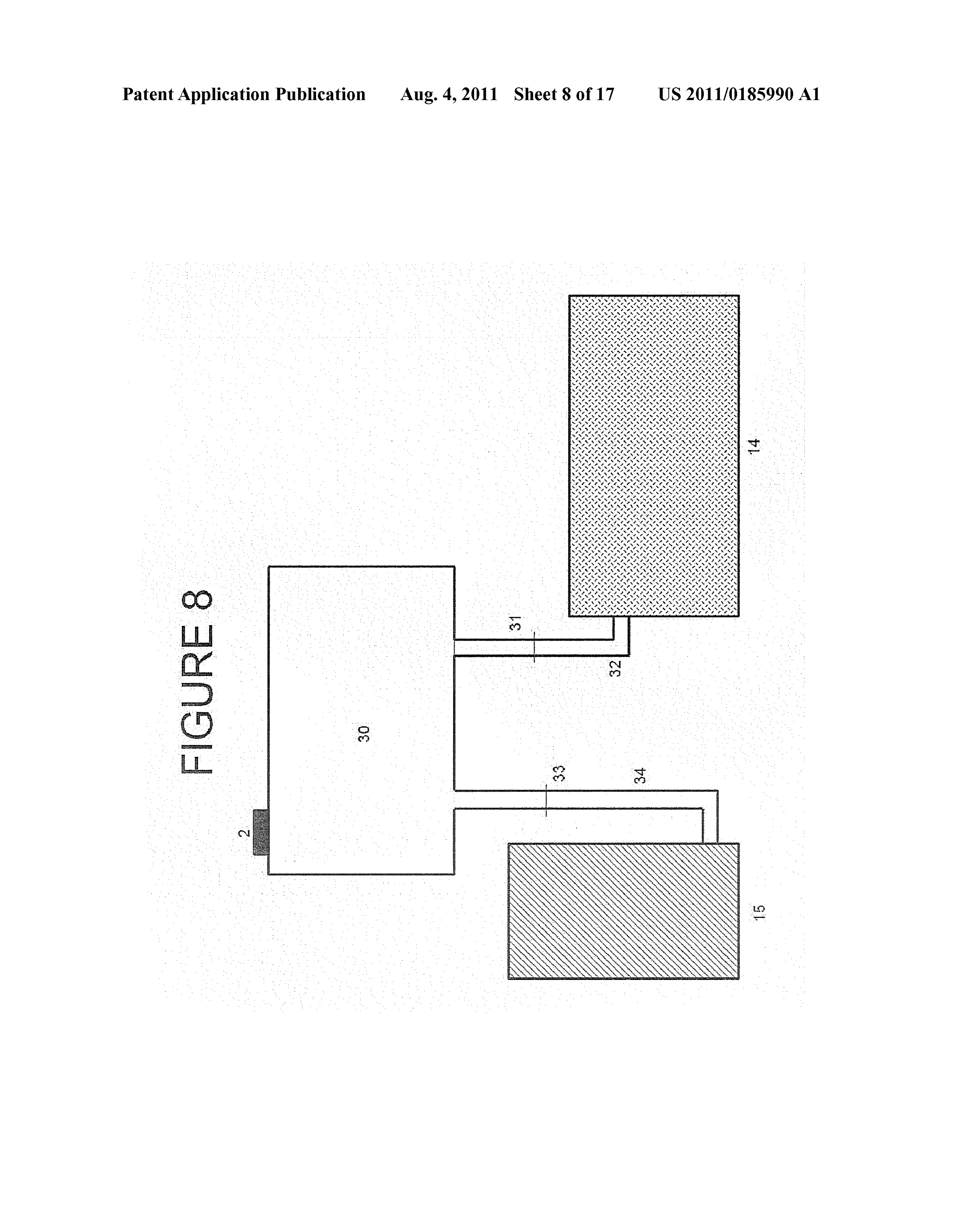
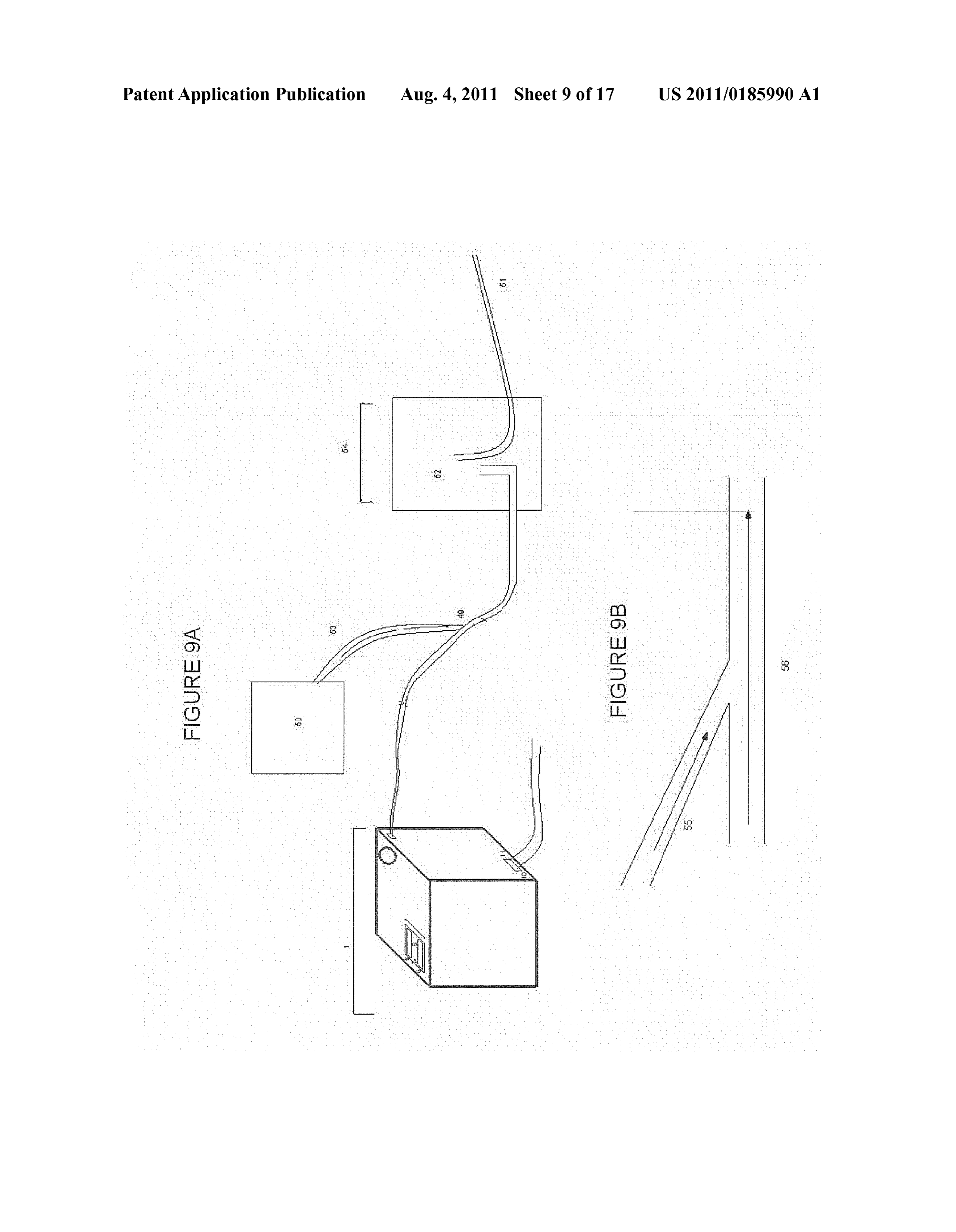
for most car drivers. 0031 FIG. 8 is a schematic diagram representing the flow 0017. Other known prior art designs present gas-produc of water from the main water source to the two components ing electrochemical fuel cells with various shortcomings. requiring water, the pressure-equalizing unit and the produc These fuel cells position the anode and cathode plates as close tion unit;
together as possible, resulting in a great amount of energy lost 0032 FIG. 9A represents the system of the present inven in the form of heat as well as requiring the system to pull tion as applied in an external combustion setting, and FIG.9B through an unnecessary amount of electricity. These older represents the means for implementing the air compressor to designs cause problems because many of today's cars are not the main line of tubing in an external combustion setting: produced with the high-output alternators that other systems 0033 FIG. 10 is a graph representing the relationship may require. between Volts and gas output;
Page 21
US 2011/O 185990 A1 Aug. 4, 2011
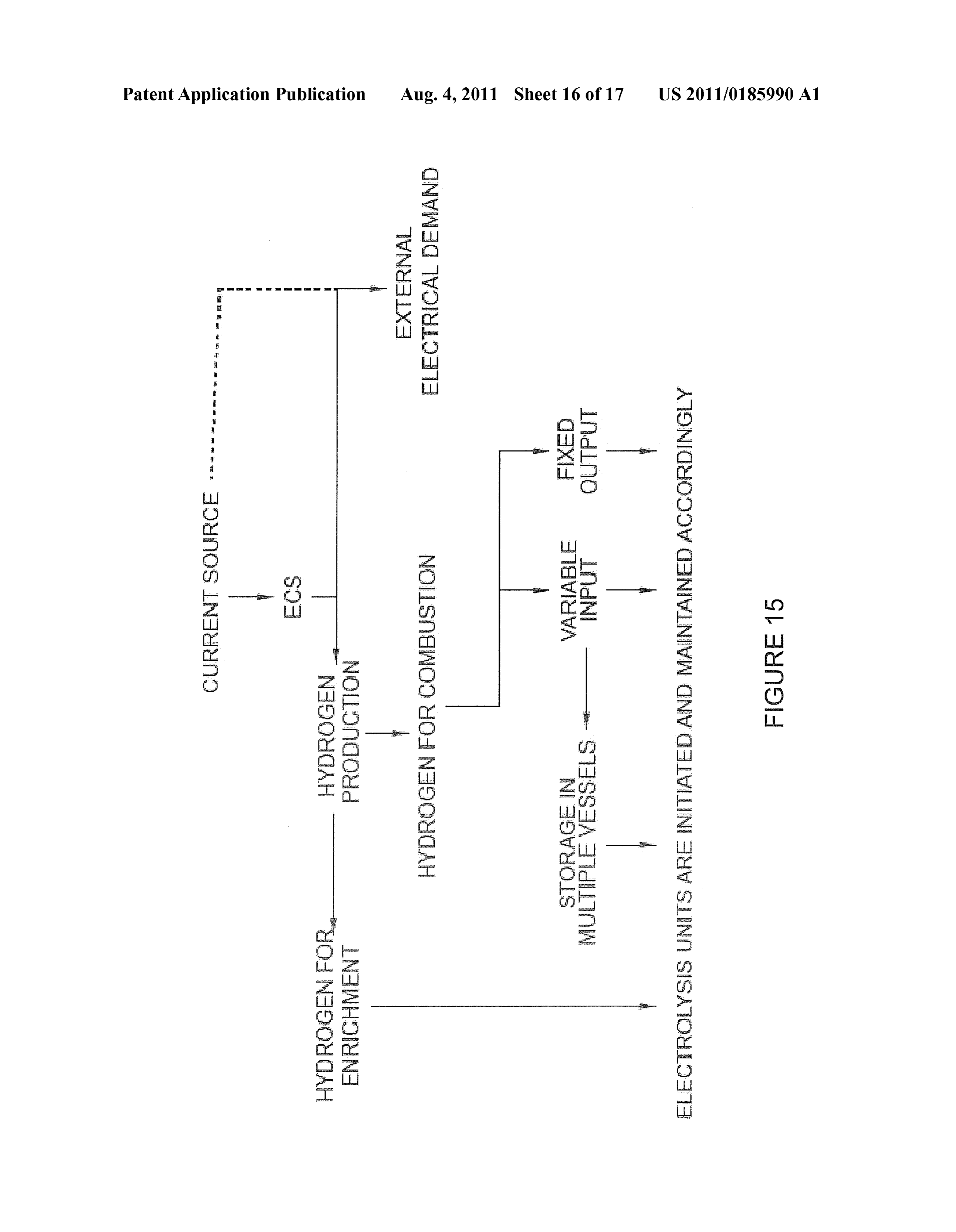
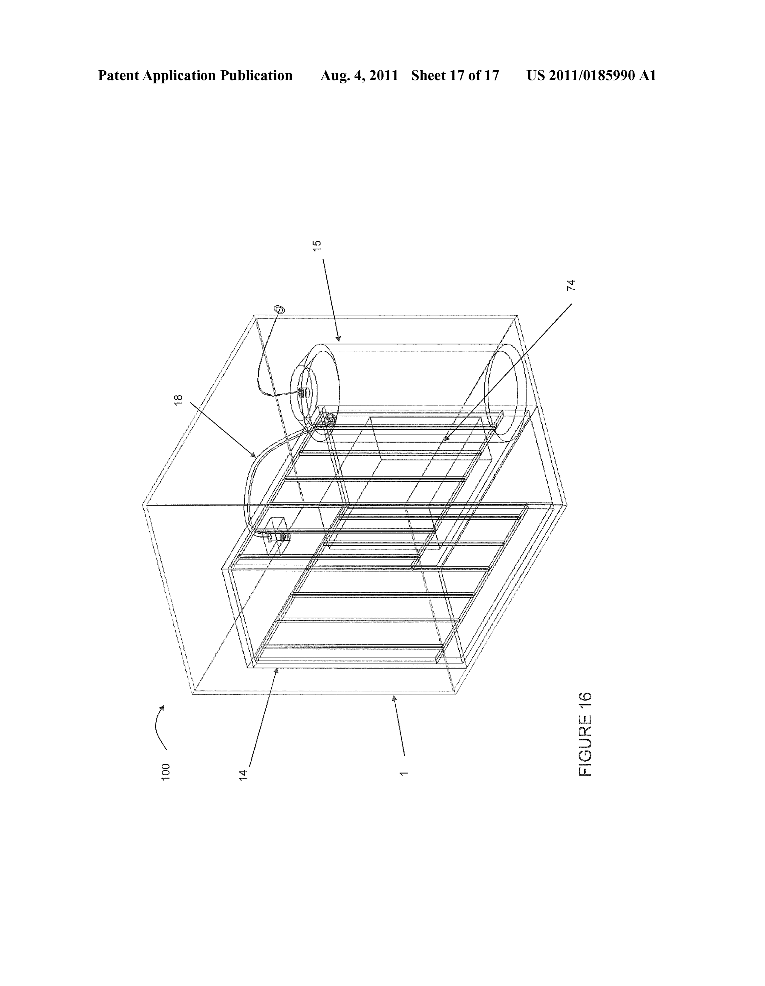
0034 FIG. 11 is a graph representing the production of Surface of the production unit (14) in a gaseous form. These hydrogen and oxygen gases in relation to the distance gases are then transported to the second main component, a between plates; pressure-equalizing unit (15) that also acts as a temporary 0035 FIG. 12A is an isometric view of a burner, and FIG. storage container for the gaseous hydrogen and oxygen prior 12B is a break-away view of the individual components of the to injection. A water storage tank (30) contains the water burner; required for both the production unit (14) and the pressure 0036 FIG. 13 is a view of the production unit with a equalizing unit (15). The gases are then transferred through a microprocessor and sensor, given length of tubing (49) to the point of injection into the 0037 FIG. 14 is a view of multiple production units: internal or external combustion. This point of injection varies 0038 FIG. 15 is a flow diagram of a power schematic of depending on whether the application utilizes an internal or the present invention; and external system of combustion, as will be explained. 0039 FIG. 16 is view of a single production unit for an 0046 FIG. 1 depicts the external architecture of the main internal combustion engine. enclosure (1) of the electrolysis unit (100) of the present invention. The main enclosure (1) of the electrolysis unit
DETAILED DESCRIPTION OF THE INVENTION (100) contains the production unit (14), pressure-equalizing 0040. The present invention provides generally for a sys unit (15), water storage tank (30), a hydrogen and oxygen gas tem including an electrolysis unit and a hydrogen-oxygen mixture outlet (3), as well as a monitoring system (4) that fuel injection system for improving combustion engines or ensures the electrolysis unit (100) is under ideal electrical devices. The present invention also generally provides for a operating conditions. As shown in FIG. 1, the electrolysis unit method of improving combustion by producing and storing is a cube that, preferably, varies slightly in size from a 10" hydrogen and oxygen gases, injecting the hydrogen and oxy cube to a 12" inch cube. Although one set of sizes is listed specifically, the present inventionallows for the proportionate gen gases into a combustion device, and performing combus enlargement of various components of the electrolysis unit tion.
0041. Through electrolysis, hydrogen as well as oxygen (100) and is neither limited nor restricted to the suggested
gas are produced in quantities directly proportional to the 0047. The production unit (14) requires the steady flow of energy input in the form of electricity. In the preferred electric current. In the preferred embodiment, the electricity embodiment, such as an internal combustion engine found in is in the form of direct current of electricity, as opposed to an automobile, the oxygen and hydrogen gases are carried to alternating current, because in order for the decomposition of the air intake manifold where the gases are combined with water molecules to occur, a constant flow of electrons is normal air and injected into the gasoline. Although the main required. In the preferred embodiment, the source of this application for the hydrogen-oxygen aided engine is the auto electrically is most simply provided by the automobiles mobile, the present invention can be applied in any setting readily available electrical system. This electricity is ideally where a combustion engine is called for. 12 Volts, however under normal conditions may range from 0042 Electrolytic cells yield amounts of product that are 11.6 volts-13.8 volts. This difference in voltage creates no proportional to the amount of current flowing through solu profound differences in the operation of the injection system, tion. This proportionality depends on a correctional constant however the greater the Voltages, the more gases will be k. This constant is unique to each cell configuration and created.
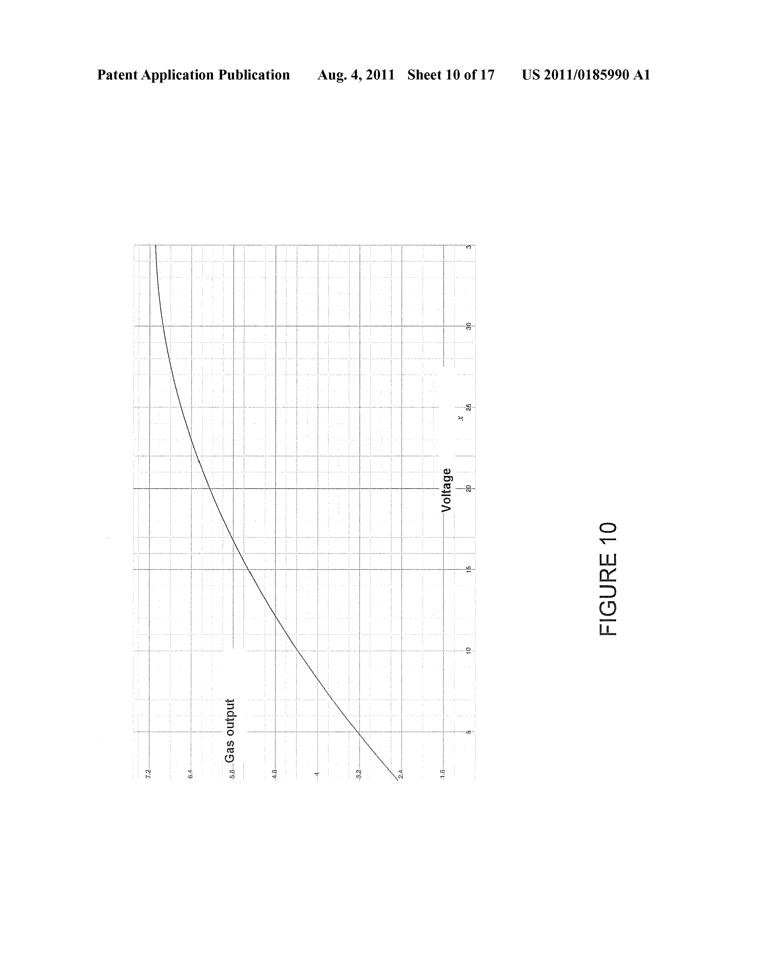
depends on a variety of design and application factors. The 0048. The relationship of volts and gas output can be seen most significant contributing factorin determining the k value as an exponential equation and is normally observed by the is the configuration of electrodes in the electrolysis units, following equation, illustrated in FIG. 10: Gas output=F(v) further described below. Other factors include concentration
of electrolyte, volume of reservoir, electrical resistivity of 0049. As shown in FIG. 10, the production of hydrogen electrodes, and all other design variations that can exist in a and oxygen gases in an electrolytic cell is estimated by the uniquely designed electrolysis unit.
0043. The gas output of the electrolysis unit, O, is electrical pressure measured in Volts (v) throughout the cir proportional to the product of the correctional design con cuit. This function is applicable to voltages from 2 V-32 v. stant, k, and the time based integral of the current, I, through 0050 FIG. 10 further demonstrates that as voltage the cell. increases, the gas output increases as well. Furthermore, as Voltage exceeds 30 volts, the slope of the graph (demonstrat ing the rate of increase of gas output) diminishes significantly.
This is precisely why a means of Voltage amplification is not
Ootal cc k It di.
utilized. In Sum, although a greater Voltage will result in a greater amount of hydrogen and oxygen gas in an electrolytic cell, 12 volts plus or minus 3 volts will not dramatically affect 0044. It therefore holds that maximizing the correctional the overall means of operation for the system. constant is a method of maximizing the output of the elec 0051 Although utilizing the automobile's pre-existing trolysis unit as a whole. Because the constituent factors in electrical system is simple and effective, in an alternative formulating k range from design to design, the most effective embodiment the system is configured to utilize DC electric way to maximize k is experimentally. current. With no major modifications to the system of the 0045. The electrolysis unit (100) of the present invention present invention, the electrical inputs can be sought available generally includes several components. First, a production from methods such as photovoltaic arrays, isolated regenera unit (14) is included in which, under electrolytic conditions, tive breaking, or reverse Solenoid methods such as rear-axel water molecules are decomposed into their raw elements, mounted induction turbines as known to those of skill in the hydrogen and oxygen. The hydrogen and oxygen rise to the art.
Page 22
US 2011/O 185990 A1 Aug. 4, 2011
0052 Although under most imaginable operating condi react with the electrodes to produce any other byproducts. tions the system's power consumption remains constant, Fluoride salts are available with a variety of cations, including under extreme environments an electrical monitoring system ammonium fluoride, potassium fluoride, and sodium fluoride. (4) provides the means to protect the automobile's electrical Properties of these solutions and other fluoride ion solutions system as well as ensuring a high level of safety is maintained differ only slightly, and therefore behave similarly in identical for the gaseous production unit (14) (depicted in FIG.3). The situations. The electrolyte acts as a catalyst to allow the elec electrical monitoring system (4) consists of a Voltammeter (6) trochemical reaction to occur, and does not actually take part as well as an ammeter (5). In the preferred embodiment, the in the overall chemical reaction. Because the electrolytes are monitoring system (4) runs of an external power Supply of 3 not consumed in the reaction, the electrolyte solution does not Volts. The circuit to power the digital read-out measurement need regular maintenance and can withstand extended oper devices is kept in isolation from the main circuit of the elec ating durations without the need to tend to the chemical trolysis unit (100) so to not interfere with the readings. The 3 electrolyte. Alternatively, sodium chloride (NaCl) can be Volt system is designed to run using 2-AA batteries (38), although other adequate 3 Volt power Supplies can be used. used as the electrolyte as described above. 0053. The voltammeter (6) is preferably of the digital 0060 Preferably, the electrodes (22) are made from pure read-out variety and ideally consists of a 4-digit LED display. carbon, especially when a fluoride electrolyte is used. Any It is necessary to have a DC voltammeter (6) that displays carbon-based electrode can be used; however, graphite is the accurate readings from 0-20 volts, or possibly higher depend cheapest and most readily available. There are wide varieties ing on whether an additional main external power Source is of graphite available. The types of graphite differ in chemical utilized. purity, Surface imperfections, and densities. Electrodes with 0054 The ammeter (5) is also preferably of the digital high-purity and the least Surface imperfections are most desir read-out variety and ideally consists of a 4-digit LED display. able for operating electrolytic units for extended periods of It is necessary to have a DC ammeter (5) that displays accu time. More advanced carbon-based materials are also Suit rate readings from 0-20 amperes. able, such as carbon nanotubes. A higher molecular Surface 0055. The system includes a master power switch, which area is key to higher level of efficiency. Platinum is another is preferably a rocker-type 2-path Switch easily accessible to material that does not react with the fluoride in solution. The the user. The switch is designed to be active at all times, electrodes (22) can also be made of a high-grade stainless however power will only be supplied while the engine is steel.
under operation. This master power switch is directed 0061. In the preferred embodiment, the exact spacing towards use as an emergency on-off toggle.
0056. The amperage is the main factor that is important to between electrodes (22) is crucial to the overall efficiency of monitor. If the amperes exceed 10 A, there are two main the cell. There are several factors, which affect the spacing features this protect the circuit from overloading, depicted in between electrodes (22) within the production unit (14): FIG. 3. Initially, the ideal safety mechanism is a time-delay 0062. As the distance between electrodes (22) decreases, fuse (7.8). The fuse (7,8) is designed to break at 10 A, with amperes increases;
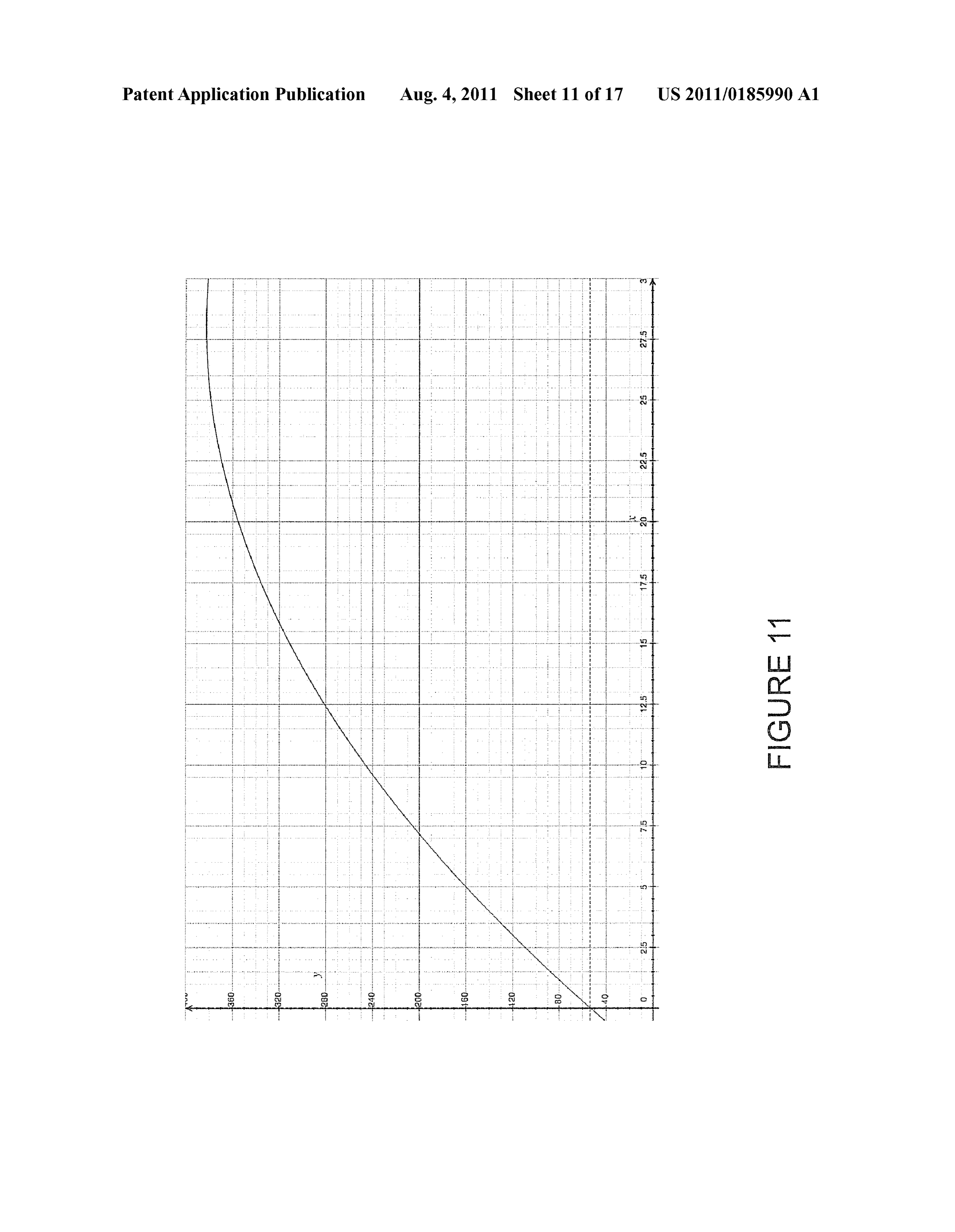
a 90 second delay. Therefore, if the system regains normal 0063 As the distance between electrodes (22) decreases, power consumption (under 10 A) the system will continue more heat is given off in the form of water vapor in a linear under normal operation. In addition, primarily in case the system of equations; and time-delay fuse fails to work as designed, an alarm Such as a buzzer (40) will activate, in other words, an audible alert 0064. As the distance between electrodes decreases (22), mechanism. The buzzer (40) is of sufficient volume so as to be the production of hydrogen and oxygen increases; however, heard by the user. Although other varieties of buzzers (40) can the increase is quadratic and its implications are seen in FIG. be used, preferably a high-pitched buzzer (40) with intervals 11.
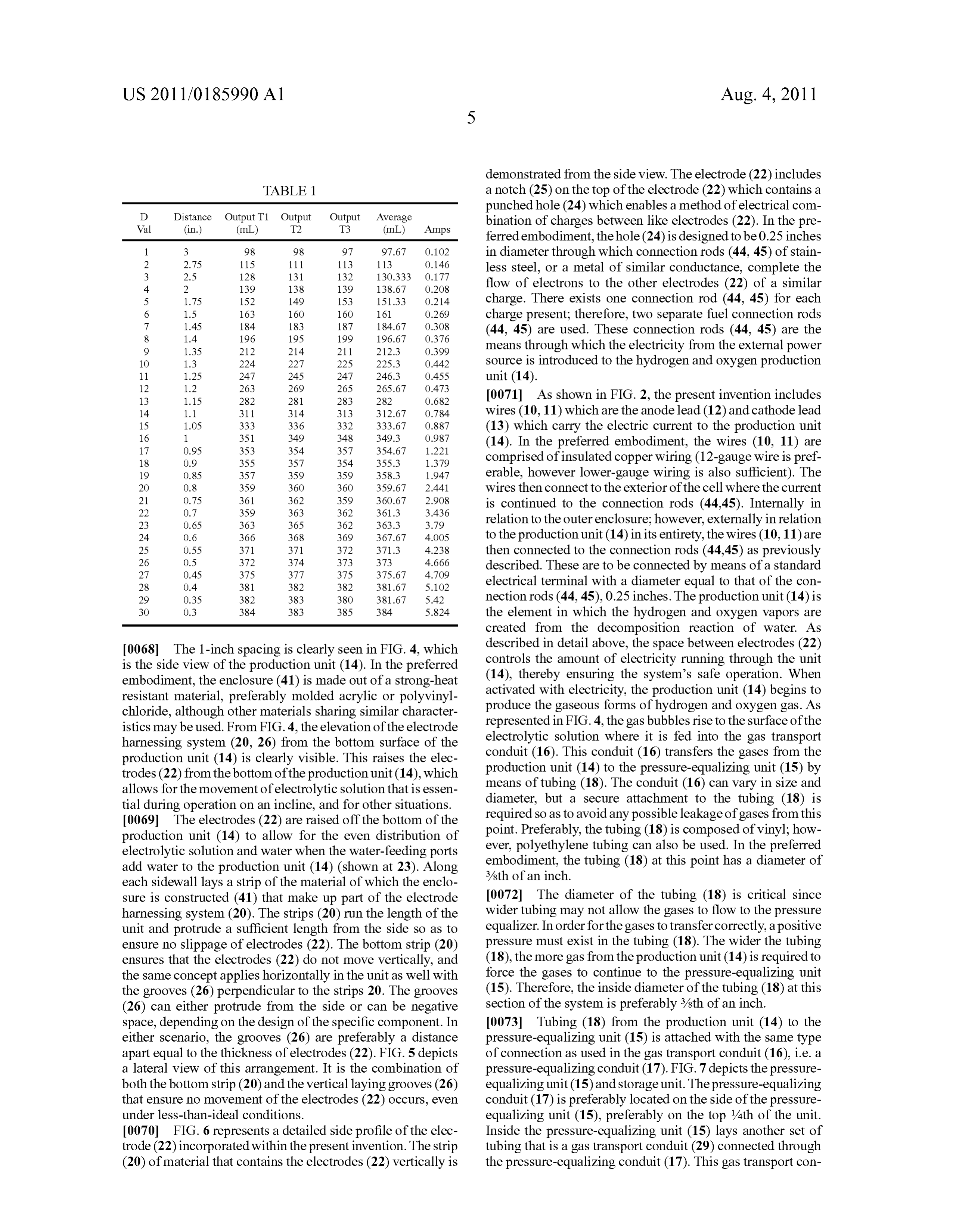
of 5 seconds is used. The user can manually use the on-off 0065. In light of the above, the spacing of the electrodes toggle rocker Switch to manually cut power to the system. (22) is crucial as it is important to produce the maximum 0057 The electrical monitoring system (4) of the present amount of gas; however, this must be done without pulling invention is designed with automation in mind, requiring no through too many amperes and without giving offexcess heat. action by the user even if a failure in the system is present, 0.066 FIG. 11 shows the production of hydrogen and oxy while also incorporating the benefits of having a manual gen gases in relation to the distance between plates. The override. X-axis represents the spacing, in which each positive integer 0058. The central component of the present invention is corresponds to an exact distance. The y-axis is the Volume of the production unit (14) for producing hydrogen and oxygen gases produced in milliliters in a 75 second time interval. The gases, as shown in FIG. 2. The production unit (14) contains electrodes (22) used were constructed out of 316-stainless a given volume of electrolytic Solution directly proportionate steel. The electrolyte was a 0.2 Molar sodium chloride solu to the dimensions of the overall cell. FIG. 4 demonstrates a tion.
lateral side view of the production unit (14). In the preferred embodiment, the production unit (14) is a rectangular prism 0067. The data below (Table 1) offers the experimental consisting of eight electrodes (22) Submerged in the electro explanation of the spacing of electrodes (22) in relation to one lytic solution. another. At the distance of 1 inch, the resulting factors reach 0059 Preferably, the electrolyte is based on the anion fluo maximum efficiency. It is at 1 inch that a high level of hydro ride. Fluoride is unique because while it has electrolytic prop gen and oxygen gases are produced, yet the amperage erties similar to most other salts, it is electrochemically inert remains below 1 amp and the heat (not shown) remains low in the described electrolysis unit (100). Fluoride, because of enough so as to not lose any quantity of water due to water its high elemental electronegativity, does not oxidize and vapor.
Page 23
US 2011/O 185990 A1 Aug. 4, 2011
demonstrated from the side view. The electrode (22) includes
TABLE 1. a notch (25) on the top of the electrode (22) which contains a D Distance Output T1 Output Output Average punched hole (24) which enables a method of electrical com
Wall (in.) (mL) T2 T3 (mL) Amps bination of charges between like electrodes (22). In the pre ferred embodiment, the hole (24) is designed to be 0.25 inches 1 3 98 98 97 97.67 O.1O2 in diameter through which connection rods (44, 45) of stain
less steel, or a metal of similar conductance, complete the 4 2 139 138 139 138.67 O.208 flow of electrons to the other electrodes (22) of a similar 5 1.75 152 149 153 151.33 O.214 charge. There exists one connection rod (44, 45) for each 6 1.5 163 160 160 161 O-269 charge present; therefore, two separate fuel connection rods
(44. 45) are used. These connection rods (44, 45) are the 9 1.35 212 214 211 212.3 O.399 means through which the electricity from the external power 10 1.3 224 227 225 225.3 O442 Source is introduced to the hydrogen and oxygen production
13 1.15 282 281 283 282 O.682 0071. As shown in FIG. 2, the present invention includes 14 1.1 311 314 313 312.67 O.784 wires (10,11) which are the anode lead (12) and cathode lead 15 1.OS 333 336 332 333.67 O.887 (13) which carry the electric current to the production unit
(14). In the preferred embodiment, the wires (10, 11) are 18 O.9 355 357 3S4 355.3 1.379 comprised of insulated copper wiring (12-gauge wire is pref 19 O.85 357 359 359 358.3 1947 erable, however lower-gauge wiring is also Sufficient). The 2O O.8 359 360 360 359.67 2.441 wires then connect to the exterior of the cell where the current
is continued to the connection rods (44.45). Internally in 23 O.65 363 365 362 363.3 3.79 relation to the outer enclosure; however, externally in relation 24 O.6 366 368 369 367.67 4.OOS to the production unit (14) in its entirety, the wires (10,11) are
then connected to the connection rods (44.45) as previously
described. These are to be connected by means of a standard 28 0.4 381 382 382 381.67 S.102 electrical terminal with a diameter equal to that of the con 29 O.35 382 383 380 381.67 S.42 nection rods (44, 45), 0.25 inches. The production unit (14) is 30 O.3 384 383 385 384 S.824 the element in which the hydrogen and oxygen vapors are created from the decomposition reaction of water. As 0068. The 1-inch spacing is clearly seen in FIG. 4, which described in detail above, the space between electrodes (22) is the side view of the production unit (14). In the preferred controls the amount of electricity running through the unit embodiment, the enclosure (41) is made out of a strong-heat (14), thereby ensuring the system's safe operation. When resistant material, preferably molded acrylic or polyvinyl activated with electricity, the production unit (14) begins to chloride, although other materials sharing similar character produce the gaseous forms of hydrogen and oxygen gas. As istics may be used. From FIG.4, the elevation of the electrode represented in FIG.4, the gas bubbles rise to the surface of the harnessing system (20, 26) from the bottom surface of the electrolytic solution where it is fed into the gas transport production unit (14) is clearly visible. This raises the elec conduit (16). This conduit (16) transfers the gases from the trodes (22) from the bottom of the production unit (14), which production unit (14) to the pressure-equalizing unit (15) by allows for the movement of electrolytic solution that is essen means of tubing (18). The conduit (16) can vary in size and tial during operation on an incline, and for other situations. diameter, but a secure attachment to the tubing (18) is 0069. The electrodes (22) are raised off the bottom of the required so as to avoid any possible leakage of gases from this production unit (14) to allow for the even distribution of point. Preferably, the tubing (18) is composed of vinyl; how electrolytic solution and water when the water-feeding ports ever, polyethylene tubing can also be used. In the preferred add water to the production unit (14) (shown at 23). Along embodiment, the tubing (18) at this point has a diameter of 3/8th of an inch.
each sidewall lays a strip of the material of which the enclo sure is constructed (41) that make up part of the electrode 0072 The diameter of the tubing (18) is critical since harnessing system (20). The strips (20) run the length of the wider tubing may not allow the gases to flow to the pressure unit and protrude a sufficient length from the side So as to equalizer. In order for the gases to transfer correctly, a positive ensure no slippage of electrodes (22). The bottom strip (20) pressure must exist in the tubing (18). The wider the tubing ensures that the electrodes (22) do not move vertically, and (18), the more gas from the production unit (14) is required to the same concept applies horizontally in the unit as well with force the gases to continue to the pressure-equalizing unit the grooves (26) perpendicular to the strips 20. The grooves (15). Therefore, the inside diameter of the tubing (18) at this (26) can either protrude from the side or can be negative section of the system is preferably 3/8th of an inch. space, depending on the design of the specific component. In 0073. Tubing (18) from the production unit (14) to the either scenario, the grooves (26) are preferably a distance pressure-equalizing unit (15) is attached with the same type apart equal to the thickness of electrodes (22). FIG. 5 depicts of connection as used in the gas transport conduit (16), i.e. a a lateral view of this arrangement. It is the combination of pressure-equalizing conduit (17). FIG.7 depicts the pressure both the bottom strip (20) and the vertical laying grooves (26) equalizing unit (15) and storage unit. The pressure-equalizing that ensure no movement of the electrodes (22) occurs, even conduit (17) is preferably located on the side of the pressure under less-than-ideal conditions. equalizing unit (15), preferably on the top 4th of the unit. 0070 FIG. 6 represents a detailed side profile of the elec Inside the pressure-equalizing unit (15) lays another set of trode (22) incorporated within the present invention. The strip tubing that is a gas transport conduit (29) connected through (20) of material that contains the electrodes (22) vertically is the pressure-equalizing conduit (17). This gas transport con
Page 24
US 2011/O 185990 A1 Aug. 4, 2011
duit (29) is constructed of a solid material, such as polyvinyl 007.9 The amount of oxygen joining the gas in the com chloride. The gas transport conduit (29) after being attached bustion chamber is critical in calculating the efficiency of the to the pressure-equalizing conduit (17) then makes a 90-de combustion. The standard composition of atmospheric gases gree turn to continue down to near the bottom of the pressure at sea level is 20.95% oxygen. Calculated from basic stoichio equalizing unit (15). metric calculations, this means that per gram of fuel com 0074 The most important aspect of the pressure-equaliz busted, the combustion chamber should ideally contain at ing unit (15) is the water (46) that it contains. The source of least 78.436 mL of atmospheric gases. Although this number the water (46) is the water storage tank (30) shown in FIG.8. may be reached at times, there is no guarantee that any Vol ume of atmospheric gases will contain the appropriate
The bottom third of the pressure-equalizing unit (15) contains amount of oxygen. Therefore, the present invention directly water. Unlike the production unit (14), this water (46) does injects oxygen as an additive, to ensure that the oxygen is the not contain an electrolytic Solution because no electrochemi excess reactant in the chemical equation. Doing so ensures cal reactions occurtherein. The purpose of the water (46) is to that the given fuel will not be limited in combustion because allow the gaseous hydrogen and oxygen gases to rise from the of the lack of oxygen. Instead of injecting normal air that end of the gas transport conduit to the top of the pressure requires 78.463 mL of gas, utilizing the system of the present equalizing unit. The gases, created in the production unit (14) invention requires only a minimal amount of gas to be added then flow through the gas transport conduit (29) and bubble up to the combustion chamber—a mere 15.6 mL, if pure oxygen (47) through the water (46). Once the gases bubble through is injected. Doing so allows Smaller engines to output a the water (46), they are free to float around in the upper greater amount of torque per cubic centimeter(CC) of engine two-thirds (55) of the unit (15). It is in this area (55) the gases Occupancy.
remain until demanded by the combustion chamber of the 0080. One important aspect of using an internal combus specific application. tion engine is that the introduction of the gas mixture must be 0075. It should be noted that the system and method of the recognized by the original sensors of the internal combustion present invention is applicable to both internal and external engine. If the hydrogen and oxygen gas is introduced without combustion systems. The following description will first adjusting the automated fuel to air ratio computing system, an illustrate the system's configuration and operation in an inter improper burning ratio will be present, causing adverse nal combustion application, followed by an illustration of an effects to the efficiency of the engine, potentially rendering external combustion application of the present invention. the introduction of hydrogen and oxygen detrimental to the 0076. As described previously, all internal combustion fuel consumption system.
engines require a sufficient amount of air in order to carry out I0081. While there is great variation for the technique of the combustion reaction to drive the engine's pistons. injecting the hydrogen and oxygen, there are several require Because of this, all internal combustion engines are designed ments that remain constant with the internal combustion to create negative pressure (a vacuum) to inhale air from an engine. The oxygen and hydrogen must mix with the atmo outside Source in an attempt to provide the attempted com spheric gases before reaching the combustion chamber. Alter bustion with a certain amount of oxygen. The end result of ations to the internal combustion engine's sensing computers this process is a strong flow of air from outside of the com must be made to correct for the change in air density. The air bustion chamber to the inside. This vacuum is utilized by the density can change dramatically with the introduction of present invention to ensure that the proper amounts of gas hydrogen because of hydrogen's lighter mass. If changes are eous hydrogen and oxygen are injected into the combustion not made to the on-board computer or sensor, the internal chamber. The present invention utilizes the air-flow already combustion engine will sense an inaccurately low air intake. present in the combustion engine together with oxygen sen This forces more air into the combustion chamber, causing sors to ensure that the proper amount of air is injected. Uti adverse effects for both fuel consumption and environmental lizing the engine's vacuum ensures that there can never be too impact. The hydrogen and oxygen gases must be drawn into much hydrogen and oxygen in the injection chamber (which the combustion chamber with vacuum pressure. This allows would risk an explosion). The engine Sucks in only the the gas mixture to be drawn into the system instead of force amount of air that it requires. fully injected. This allows for the continued use of the 0077. When the engine is demanding air via the negative onboard internal combustion engine computer. pressure in the air intake manifold, this creates Suction in the I0082. The second way in which the present invention aids tubing (18) from the pressure-equalizing unit (15) to the air the combustion process is by temporarily raising the heat in intake itself. The suction then makes its way to into the the combustion chamber. At times, when too little heat is pressure-equalizing unit (15), wherein for each unit of nega present in relation to the heat needed for complete combus tive pressure that is applied to the pressure-equalizing unit tion for a certain fuel, excess reactants will form. For (15), the pressure-equalizing unit (15) releases a given quan example, when normal gasoline is burned in a standard auto tity of hydrogen and oxygen through the release conduit (21) mobile, a given amount of carbon dioxide is produced. This to flow through the final length of tubing (19), which feeds carbon dioxide is present because too low a temperature was directly into the air intake manifold as shown in FIG. 2. present in the combustion chamber, ultimately resulting in the 0078. At this point in the process, the hydrogen and oxy production of carbon dioxide gases. gen enhance the engine's combustion of the gasoline. The two I0083. The present invention offers hydrogen as an additive main factors that control the efficiency of any combustion to provide a solution for this source of inefficiency. Hydrogen reaction are the amount of oxygen present in the atmosphere gas, when in combination with oxygen, has a significantly Surrounding the combustion and the heat of the combustion. higher burning temperature than gasoline. Therefore, in a The present invention is directed towards altering both of combustion engine when the sparkplug provides the spark for these factors, thereby improving the efficiency and facilitat combustion, the hydrogen and the oxygen burn at the same ing a more complete combustion of fuel. time as the gasoline. When the hydrogen and oxygen com
Page 25
US 2011/O 185990 A1 Aug. 4, 2011
bust, however, the temperature is raised. In doing so, the duced in conjunction with other fuels to result in a lower higher burning temperatures raise the temperature in the burning temperature. Burning the hydrogen and oxygen with chamber, thereby resulting in a higher level of efficiency for out the presence of other gases is the most efficient way to use the internal combustion reactions. the technology. Furthermore, the combustion of hydrogen 0084. The system of the present invention can also be used and oxygen alone results in water vapor as the only byproduct with external combustion engines, including any other appli of the reaction. This water vapor byproduct maintains a high cation that burns gaseous fuel to add heat to the system. temperature immediately after combustion occurs, and can be Although the properties of enhancing combustion remain utilized in any way that steam is already used. constant for external combustion reactions, the method of 0088. One of the most common uses for external combus injection differs dramatically. Unlike internal combustion tion is in Steam heating applications. The combustion of engines, such as in automobiles, external combustion cham hydrogen and oxygen can be used to provide the heat to bers provide very little vacuum pressure. The point of com convert liquid water to vapor. The efficiency is further bustion is more open and allows for the natural circulation of increased as the byproduct water vapor can be introduced to air. Therefore, in order to implement the system of the present the existing steam manifold and delivery system. As the water invention, another source of pressure must be incorporated in vapor is utilized to convert the thermal energy to work, the order to ensure that sufficient amounts of gaseous hydrogen vapor is cooled and condenses to liquid water. This water can and oxygen gases are present at the point of combustion. then be used to supply the water required by the electrolysis I0085 FIG.9A represents a method of injection for exter units (100), resulting in a closed system with no wastewater as nal combustion applications. The production unit (14) is well as higher levels of thermal efficiency. present and remains the most important aspect of the system. I0089. As previously mentioned, the system of the present After the gas is created in the production unit (14) and travels invention includes a method of water distribution to the vari to the pressure-equalizing unit (15), the gas requires a source ous components of the injection system. The two units requir of negative pressure, or a vacuum, to be actively injected into ing a set amount of water are the production unit (14) and the the combustion chamber. In the preferred embodiment, this pressure-equalizing unit (15). In the preferred embodiment, Source is a small-scale air compressor (50). The air compres as depicted in FIG. 8, there exists one main tank for the water Sor (50) forces a given amount of atmospheric gases through (30) that is accessible by a removable cap (2). The cap (2) a gas conduit (53) through the tubing (49) to the point of should preferably be child-tamper proof to avoid the possi combustion (52). Alternatively, low-pressure regulators spe bilities of water leaking. To control the amount of water cifically designed for hydrogen gas transfer can be used. If the allowed into each unit, the piping (32. 34) is inserted at a gases are required to travel longer distances where the pres specific distance from the bottom of each respective unit (14. Sures are not sufficient to utilize passive regulation mecha 15). For example, a higher water level is required in the nisms, pumps can be required. Preferably, this is not the case production unit (14) in relation to the pressure-equalizing unit with the present invention; however, because the gas mixture (15), and, therefore, the pipe (32) is inserted at a greater is produced locally and does not have the travel great dis distance from the bottom of the production unit (14) itself. tances. When applied to the same tubing as the production The pipe (34) connecting the water from the main storage unit (14) connects to, vacuum pressure is created. Therefore, tank (30) to the pressure-equalizing unit (15) is at a distance the gases are released from the pressure-equalizing unit (15) approximately /3 from the bottom of the unit. As an added and sent through the tubing (49) to the external combustion safety precaution, butterfly valves (31,33) are present on each chamber (54). The means for implementing the air compres of the pipes (32, 34) providing water to the various compo sor (50) to the main line of tubing (49) is shown in detail in nents. Although not readily accessible to the user in the pre FIG. 9B. This demonstrates that the airflow from the air ferred embodiment, in the case of required maintenance or compressor (55) is connected at an angle to the current tubing further testing, the valves (31.33) can provide the means (56). This ensures that a sufficient amount of gases are drawn necessary to precisely control the amount of water flow. from the pressure-equalizing unit (15). 0090 The system of the present invention can further I0086. The external combustion chamber (54) contains the include a computing system. There are two main purposes for key components for any external combustion application. the computing system; live safety monitoring, and live opti Present is a fuel line (51) which transports the given fuel to the mization adjustments. An additional benefit of the computing point of combustion (52). Once ignited, the point of combus system is to receive data to a main data hub via a live web tion (52) maintains a constant flame. When the combustion server connection, further discussed below. This wealth of begins, the user activates the present invention. This begins data is used for a broad range of optimization and calibration the production of hydrogen and oxygen gases. The air com efforts for any.
pressor (50) then creates the vacuum pressure required to 0091. The computing system includes a low-power micro transport all necessary hydrogen and oxygen gases to the processor (74) and a variety of sensors (76). The sensors (76) point of combustion (52). As described above, this aids the are specific to the application, however certain sensors (76) combustion by both ensuring proper levels of oxygen and are consistent through all applications: temperature sensors, increasing the heat of combustion by the burning of hydrogen pressure sensors, Voltmeters, ammeters, and a UV light sen gases. sor. The microprocessor (74) can also include a fuse (39) with 0087. The hydrogen and oxygen fuel mixture can be used or instead of digital current controls, and the fuse (39) can be to entirely replace the existing combustible fuels for an exter connected to the main wiring shown in FIG. 3. nal combustion system, or can be used in a ratio with existing 0092 Although a copy of the data is sent to the webserver, fuel gases. Burning the hydrogen and oxygen gases alone local copies of data are stored temporarily. As the data is from other gases (natural gas, propane, etc) results in higher collected, the computing system runs an algorithm calculat heats in the combustion chambers. For systems that require ing hydrogen and oxygen gas outputs. These results are then the heat to be limited, the oxygen and hydrogen can be intro compared to the optimized results to see if the system must
Page 26
US 2011/O 185990 A1 Aug. 4, 2011
make any changes. If required, the microprocessor is powering on or off the production units (14). Max current can equipped to actuate different control outputs for optimization. be seamlessly limited to an individual production unit (14). 0093. The main benefit of adding an on-board computer Because output for each production unit (14) is proportional for the system is the added safety. This computing system is to current, this is an effective means to limit output. Limiting capable of immediately detecting any leaks or other poten current is the easiest way to adjust output for the individual tially dangerous situations. The computing system has full production unit (14); however, it can also be achieved by capabilities to cut power to the production unit (14) as well as altering the electrolyte concentration, operating temperature, activating a solenoid that disrupts the central tubing (49) and more factors.
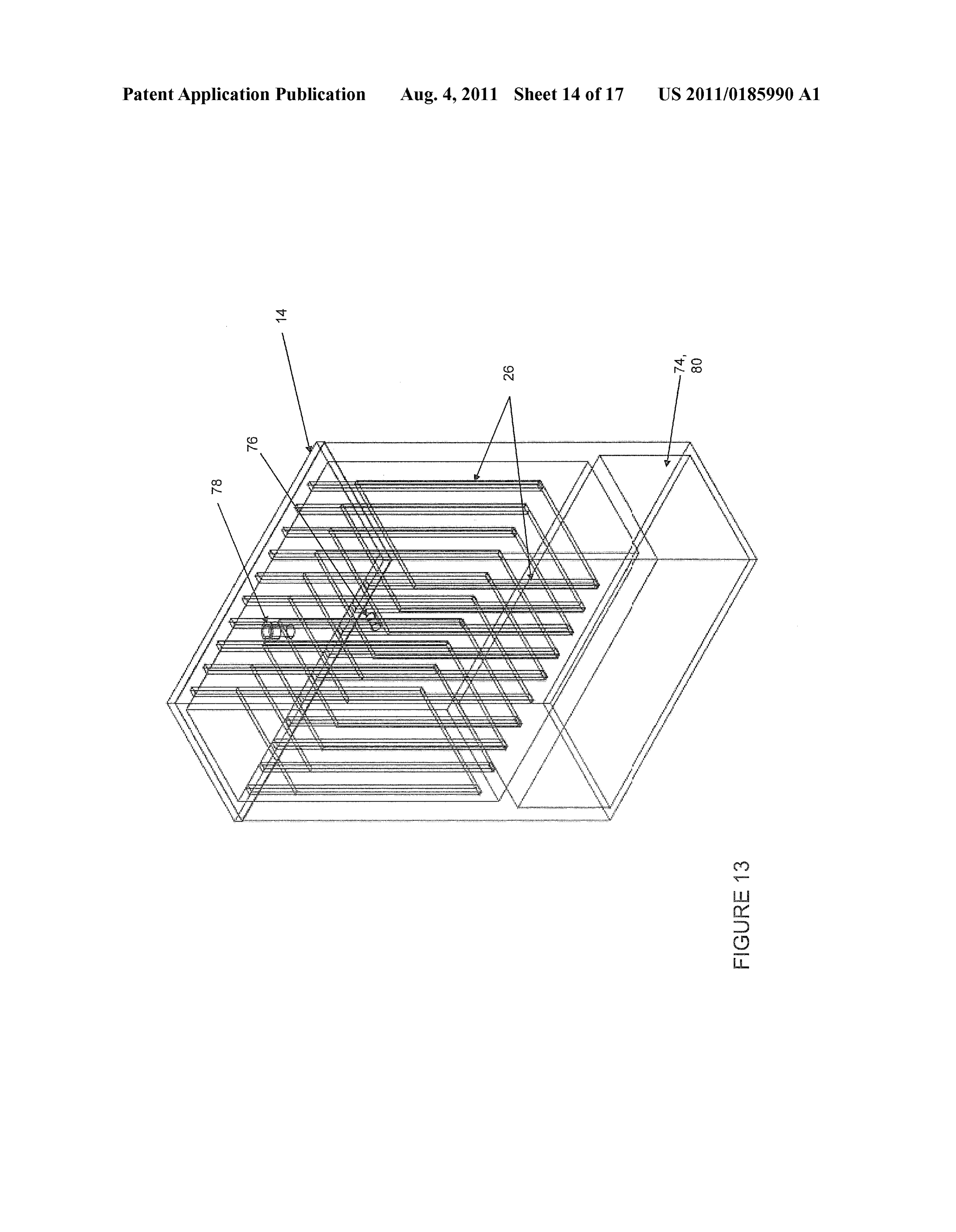
continuity. The computing system can be added to any of the (0099 FIG. 13 shows an example of the production unit parts of the present invention as necessary. (14) including a microprocessor (74) and sensors (76). This 0094. The complexity of the computing system varies particular production unit (14) is designed with modularity in depending on the desired system. The computing systems are mind because it can be used in Systems that require multiple embedded within the production units (14) themselves, and production units (14). A gas outlet valve (78) can be included are user controlled via an electronic control system (ECS). so that gases produced by the electrolysis can escape before The ECS varies inappearance and functionality depending on the application. Automobiles, for example, have a simple use. This valve (78) is beneficial to be of a type used for the ECS that allows only for basic system functions. This is typical handling of hydrogen. A specialized hydrogen valve because automobiles operate with one production unit (14) (78) can reduce the amount of gases that escape the electroly and therefore do not have many user controls. sis unit at connection points. Electrode harnesses (grooves) 0095 More complex systems that utilize many production (26) hold the electrodes (22) in place and supply the electrical units (14) have an ECS with accordingly more options. The connection. There are preferably ten graphite electrodes (22) ECS for these complex systems have the ability to control all that are suspended above the bottom surface of the reservoir aspects of the functionality of the system as a whole. This as to allow for uninhibited flow of electrolyte solution includes a variable output system, variable input, and any throughout the container. The microprocessor (74) is located specific controls that can be required depending on the appli in an under mount space (80). The microprocessor (74) fits cation. within the volume ceilinged by the bottom surface of the 0096. In conjunction with the computing system electrolyte reservoir. The microprocessor (74) is equipped described, a web server is used to compile a master set of with a variety of sensors (76) that are distributed throughout usage data. This connection can be maintained via Bluetooth, the production unit (14). This space allows for the wiring of Wi-Fi, or Ethernet connections. Each unit uploads to its own Such components while keeping the design fully modular. database, a continually updated XML directory containing The quantity and variety of sensors (76) within the production output data from sensors described in the computing system. unit (14) depends on the application for the system as whole. The webserver has connections with both the ECS and the For example, a pressure sensor (76) is shown that can play a embedded microprocessors in the production units (14). critical role in the functionality of the computing system and While the connections between the two types of computers the present invention as a whole. A hole can be included to are traditionally hard-wired, they both have the capabilities to allow the sensor (76) to collect data within the production unit communicate wirelessly, offering the ability to be controlled (14).
off-site. 0100. A single production unit (14) can also be used as 0097. The modularity of the system is critical to its usabil shown in FIG. 16 generally for injection in an internal com ity. Local "on-location hydrogen demand varies like any bustion engine. The parts are essentially as described above. combustible fuel. Therefore, the system must be able to vari The engine pulls a vacuum pressure at the main mixture ably produce hydrogen, instead of at a constant rate which output, which creates a perfectly constant gas flow to the enables the possibility for large amounts stored at one point, engine from the pressure-equalizing unit (15). In this situa or on the opposite end, a shortage. Both cases can be tion, the microprocessor (74) at the very least handles the extremely detrimental, depending on the application. production of hydrogen and oxygen inside the production 0098. The desired output (and other functional variations) unit (14). For many applications, this is also used to monitor/ is controlled by the electronic control system (ECS) in con control the end result as well. There needs to be constant junction with the microprocessors in the production units pressure through the tubing (18) from the production unit (14) (14). The ECS is the user interface and means for power to the pressure-equalizing unit (15). Furthermore, this pres distribution that communicates with the microprocessors in Sure needs to be greater in magnitude than the magnitude of the individual production units (14). There are two main ways vacuum pressure, otherwise no gas mixture can be supplied to the system can limit (more precisely control, because it can the engine.
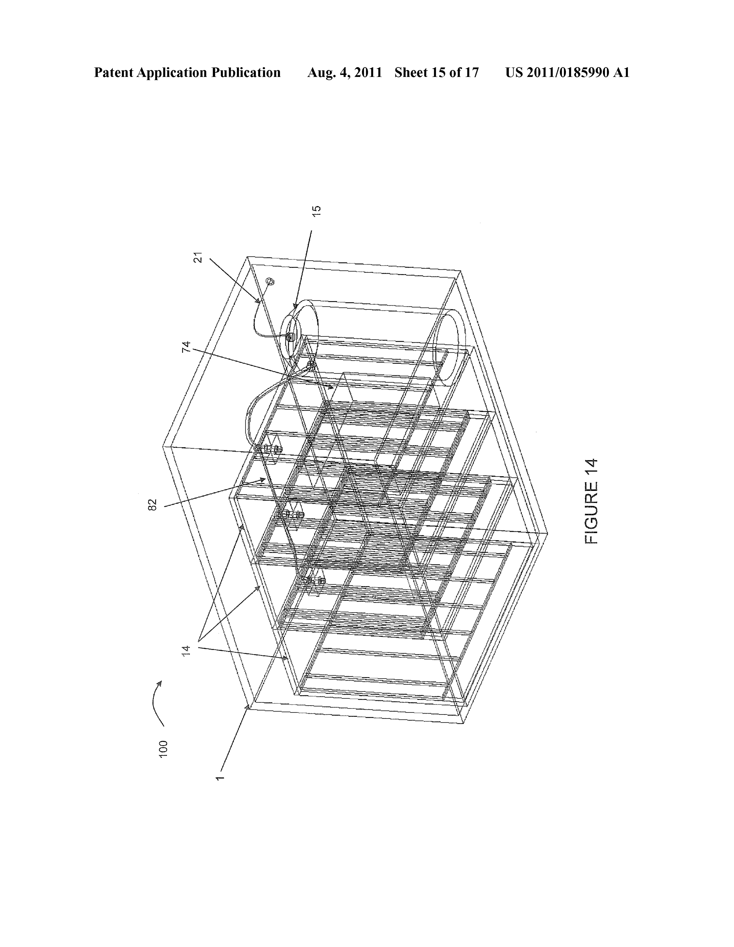
also increase production) hydrogen production. First the sys 0101 Multiple production units (14) can be used as shown tem can power on/off entire electrolysis units. Some applica in FIG. 14. Three production units (14) are shown combined tions have only one production unit (14). For higher output with a single pressure-equalizing unit (15) within an enclo systems that have multiple production units (14), the system sure (1). All of the production units (14) are controlled by the can at any time shut off or turn on any number of units (14). ECS that includes microprocessor (74). At least one conjunc Because the reaction is electrically dependant, output ceases/ tion manifold (82) is included in this design so that the pro initiates almost instantaneously. With the electrolyte and duced gases from all three production units (14) gather prior electrode chemical compositions described herein, the pro to flowing to the pressure-equalizing unit (15). This is to duction units (14) do not suffer adverse effects from either ensure additional safety because of the greater potential for a extended time periods of operation, or periods of inaction. buildup of pressure with multiple production units (14). The Second, conditions can be controlled within the activated production units (14) are easily joined with the conjunction production units (14). Output can be adjusted without entirely manifolds (80). The combined hydrogen and oxygen output
Page 27
US 2011/O 185990 A1 Aug. 4, 2011
for the three production units (14) flows through the release receives live data from microprocessors (74) within, repre conduit (21) through the final length of tubing (19) as senting the operating conditions within each part of the sys described above as an outlet. tem.
0102) Another way multiple production units (14) can be 0110 Certain applications call for the maximum amount used together in a joint system is if their gas outputs are of gases to be produced for any variable power input. This can directed towards different uses. In this case, they are still be a solar panel which directly Supplies time-varying current, operating under the same current Source, but have separate at which point the ECS distributes power to the production production and injection details. Like fuel cells, the present units (14) in a manor to produce the largest amount of com bustible fuel.
invention's production units (14) can be stackable, and banks 0111. In general, the system is not designed for long-term of production units (14) for larger Volume hydrogen and storage or transport of the hydrogen and oxygen gas mixture. oxygen output are a great utilization of the technology. When user activated, the ECS directs the gas flow to a given (0103 FIG. 15 shows a flow diagram of the distribution of reservoir at low pressure. When the maximum or designed current from the initial power source as it is allocated through pressure is achieved, the ECS automatically stops flow into the ECS. Starting at the current source, this is the source of the according vessel.
electrical energy that the system requires. Ideally the source is 0112 The end result of any desired option of this power renewable, resulting in a carbon neutral footprint. In automo distribution schematic is the ECS communicating with the biles the current source is at the least the alternator, and is microprocessors (74) in each production unit (74) to achieve more efficient with the addition of other renewable sources of the desired results.
electric current. Non-automotive applications can have more 0113. One of the main benefits of the present invention than one current Source (feed from batteries, Solar panels, compared to current leading hydrogen technologies, is the wind turbines, etc) and this current source is the combined low pressure nature of the system. Instead of storage vessels power from these sources. containing hydrogen at above 500 psi, the present invention 0104. The ECS, as described above, is the user interface keeps the pressure of combustible gases at or near atmo where any possible system configurations are accessible. spheric pressure conditions. This has dramatic results on the Because a major application for the present invention is for applications of the technology as a whole. Hydrogen storage off-grid systems, the ECS can also be used to route power to and transport technologies are still limiting the progress of any other devices requiring electrical energy. For hydrogen utilizing hydrogen as an energy source. High pressure hydro production in systems using one production unit (14), the gen systems have an increased amount of “waste hydrogen”: ECS can be as simple as a switch. For systems that have hydrogen that is unused because it is lost in the storage and multiple production units (14), the ECS is responsible for transportation steps.
communications between the production units (14). 0114. The present invention combusts the hydrogen near 0105. As the ECS also functions as an overall power dis the rate of production. This concept, unseen in hydrogen tributor, a certain amount of power can be required for exter combustion technologies, allows for hydrogen production nal demands. This amount of electrical energy dedicated to units for any size or scale application. Because the present external demands is user defined, and can vary with time or invention is effective even at Small scale, major infrastructure load factors. For example, ifa system utilizes Solar panels that is not required for the initial implementation of the technol Ogy.
outputs 500 watts and there is a need to supply 200 watts to 0115 While at low pressures, the hydrogen is easily trans other electrical devices, the remaining current will be man ported to temporary storage vessels from which the gases are aged by the ECS to deliver power most efficiently to the transported for combustion or enrichment applications. After production units (14).
0106 Electricity is then dedicated for hydrogen produc the hydrogen vacates the production unit (14) where it is produced, is it transported via tubing (18) to the temporary tion. The total available power is dedicated to producing the storage vessel of the pressure-equalizing unit (15). The posi mixture of hydrogen and oxygen. Quantifiably, this is the total tive pressure of the gases being produced from the electroly current subtracted by the total current required by external sis unit (100) are the only motive forces for the gas mixture at
SOUCS.
this point.
0107 Controls on the ECS allow for the production of 0116. The present invention can also be used more gener oxygen and/or hydrogen for chemical enrichment processes. ally as a hydrogen enrichment system. Combusting hydrogen When desired, the ECS can be utilized to change the propor with the oxygen is not always the best way to utilize the tions at which the oxygen and hydrogen are produced. These hydrogen. Because of hydrogen's unique chemical proper precise ratios allow the gases to be utilized informs other than ties, it is used in the enrichment of other fuels. Biofuels are a combustion. perfect example where the chemical enrichment process 0108 Next, the amount of current is allocated towards using hydrogen adds to the effectiveness of the fuel. For Supplying power to the production units (14). Within each varieties of applications where the hydrogen is chemically production unit (14), power is Supplied to the microprocessor used precombustion, the desired ratio between the hydrogen (74) as well as the electrodes (22) that create the potential and oxygen can be different than what is required for com difference required for the electrochemical reaction to occur. bustion. Therefore, the electronic control unit has the ability 0109 The fixed output is for use where a specific flow rate to change these proportions. The method of hydrogen enrich of the combustible gas mixture is required. This user-defined ment varies greatly depending on the chemical compounds or value can be in units offlow rate, potential combusted energy mixtures being enriched. Once the gas mixture is collected, output, mass of gas mixture, etc. The ECS has controls that any standard means of enrichment can be used. can provide a constant gas output. The ECS is responsible for 0117 The present invention can be used in combination allocating power across multiple production units (14), and with a dual gas burner 60, shown generally in FIGS. 12A
Page 28
US 2011/O 185990 A1 Aug. 4, 2011
12B. In general, the term “dual gas burner” refers to an 0.124. The invention has been described in an illustrative apparatus designed to combust a primary fuel source (hydro manner, and it is to be understood that the terminology that carbon fuel-fossil fuel) in the presence of a secondary fuel has been used is intended to be in the nature of words of Source. The secondary fuel source in the case of the present description rather than of limitation. invention is mixture of hydrogen and oxygen gases produced 0.125 Obviously, many modifications and variations of the from the electrolysis units (100). Any device that burns a present invention are possible in light of the above teachings. hydrogen carbon fuel utilizing a burner can easily be adapted It is, therefore, to be understood that within the scope of the to burn with the additional presence of hydrogen and oxygen described invention, the invention may be practiced other gases. This can be achieved in many ways; however, a simple wise than as specifically described. design is shown in FIGS. 12A-12B. What is claimed is:
0118. The dual gas burner 60 includes a primary gas mani 1. A system for improving combustion comprising: fold 62 that is used to introduce the primary (hydrocarbon) electrolysis means for producing and storing hydrogen and gas into the top (primary) sectional fuel rail (68), as well as a oxygen gases operatively connected to injection means secondary gas manifold 64 where a regulated hydrogen and for injecting said hydrogen and oxygen gas into a com oxygen mixture is introduced to the bottom (secondary) fuel bustion device.
rail 66 in the dual gas burner 60. A gas membrane 70 separates 2. The system of claim 1, wherein said electrolysis means the primary gas from the secondary gas, and its properties is further defined as at least one production unit operatively vary depending on the composition of gases. Once in the connected to a pressure-equalizing unit within an enclosure. secondary fuel rail 66, the secondary gas passes the gas mem brane 70 to combine with the primary gas before combustion 3. The system of claim 2, further including a water storage occurs. After the gases are premixed in the primary fuel rail tank operatively connected to said production unit and said 68, they escape together through combustion points 72 (i.e. pressure-equalizing unit.
the ignition points for the burner), which are essentially holes 4. The system of claim 3, wherein said water storage tank in the top of the primary fuel rail 68. includes pipe means for controlling an amount of water 0119 Most commonly, these types of burners 60 combust allowed into said production unit and said pressure-equaliz conventional natural gas or propane. The efficiency of these ing unit.
burners 60 can be increased by the addition of the hydrogen 5. The system of claim 4, wherein said water storage tank and oxygen gas mixture produced by the present invention. includes a cap and valve means for controlling water flow. 6. The system of claim 3, further including monitoring 0120. The addition of hydrogen and oxygen into the com means for ensuring ideal operation of said electrolysis means. bustion of fuels helps in several main ways. First, the addition 7. The system of claim 6, wherein said monitoring means of combustible hydrogen adds heat to the system. Hydrogen includes a Voltammeter and ammeter with displayS. in the presence of oxygenburns at much higher temperatures 8. The system of claim 7, further including a time-delay than do hydrocarbon fuels. In addition, the high flame propa fuse that breaks at 10 A with a 90 second delay. gation properties of combusting hydrogen aid the complete combustion of the fossil fuels. Therefore, with the addition of 9. The system of claim 8, further including an audible alert mechanism.
hydrogen and oxygen to a fossil fuel burner there is a much greater energy output. Furthermore, because the hydrogen 10. The system of claim 6, further including electric current recombines into water vapor when combusted, and hydro means for Supplying electric current to said production unit. gen's flame propagation results in a more complete combus 11. The system of claim 10, wherein said electric current tion of the fossil fuels, the overall toxic and greenhouse gases means is an electrical system of an automobile. are dramatically lowered. 12. The system of claim 10, wherein said electric current 0121 Dual gas burners 60 can be used in countless appli means is DC current.
cations. Steam boilers, for example, are effective use of this 13. The system of claim 10, further including a master technology. Dual gas burners 60 can be safely used for cook power switch.
ing because of its clean burning nature. The food industry has 14. The system of claim 13, wherein said production unit a need for this technology, as it can offer extremely high includes electrodes Submerged in an electrolytic Solution temperatures with an even heat distribution through space (as including water.
applied to a closed oven, for example). 15. The system of claim 14, wherein said electrolytic solu 0122) The ratio between the size of the primary 68 and tion is chosen from the group consisting of a solution includ secondary fuel rails 66 and the permittivity of the gas mem ing fluoride anion and a sodium chloride solution. brane 70 depends on type of hydrocarbon fuel applied. The 16. The system of claim 14, wherein said electrodes are individual flow rate regulation of the primary and secondary made of a material chosen from the group consisting of a pure gases is an easy method to change the properties of the flame carbon composition, graphite, carbon nanotubes, platinum, produced in the combustion reaction. Once calibrated, the stainless steel.
dual gas burner 60 as described can be automated utilizing the 17. The system of claim 14, wherein said electrodes are electronic control system (ECS). A desired heat output from spaced one inch apart from one another. the burner 60 can be controlled and monitored via the ECS. 18. The system of claim 14, wherein said electrodes are 0123. The above presents a method for burning the hydro elevated with an electrode harnessing system from a bottom gen and oxygen mixture with another primary fuel source. portion of said production unit. Another option for the combustion of the hydrogen and oxy 19. The system of claim 18, wherein said electrode har gen mixture is a hydrogen gas burner as described by Stanley nessing system includes strip means for preventing vertical Meyer in U.S. Pat. No. 4,421,474. This is an effective way to movement of said electrodes and groove means for prevent combust the mixture. ing horizontal movement of said electrodes.
Page 29
US 2011/O 185990 A1 Aug. 4, 2011
20. The system of claim 18, further including connection enclosure, and electronic control means for controlling an means for completing the flow of electrons to electrodes or a amount of hydrogen and oxygen produced. similar charge and for providing electricity to said production 41. A method of improving combustion, including the steps unit. of:
21. The system of claim 14, wherein said production unit producing and storing hydrogen and oxygen gases; further including a gas transport conduit operatively con injecting the hydrogen and oxygen gases into a combustion nected to tubing that is operatively connected to said pres device; and
Sure-equalizing unit with a pressure-equalizing conduit. performing combustion.
22. The system of claim 21, wherein said tubing has a 42. The method of claim 41, wherein said producing step is diameter of 3/8th of an inch. further defined as electrolyzing a solution including water in 23. The system of claim 21, wherein said pressure-equal at least one production unit and producing hydrogen and izing unit further includes a gas transport conduit that empties OXygen gases.
in a bottom portion of said pressure-equalizing unit. 43. The method of claim 42, wherein the solution is chosen 24. The system of claim 21, wherein a bottom third of said a solution including fluoride anion and a sodium chloride pressure-equalizing unit contains water from said water Stor Solution.
age tank, and an upper third contains said gases created in said 44. The method of claim 42, further including the step of production unit. providing electricity to perform said electrolyzing step. 25. The system of claim 2, wherein said injection means 45. The method of claim 44, wherein said providing step is further includes negative pressure means for creating Suction further defined as providing electricity from a source chosen in the pressure-equalizing unit. from the group consisting of an automobile electrical system 26. The system of claim 25, wherein said injection means and DC current.
are operatively connected to an internal combustion engine 46. The method of claim 42, further including the step of and said negative pressure means is an air intake manifold. preventing movement of electrodes and maintaining the elec 27. The system of claim 25, wherein said injection means trodes above a bottom portion of the production unit. are operatively connected to an external combustion engine 47. The method of claim 42, further including the step of and said negative pressure means is an air compressor. monitoring and displaying operating conditions of the elec 28. The system of claim 27, wherein said external combus trolyzing step.
tion engine is part of a steam heating device. 48. The method of claim 41, further including the step of 29. The system of claim2, wherein said injection means are breaking a circuit when amperage is exceeded. operatively connected to a dual gas burner. 49. The method of claim 48, further including the step of 30. The system of claim 29, wherein said dual gas burner activating an alarm when amperage is exceeded. includes a primary gas manifold operatively connected to a primary fuel rail, and a secondary gas manifold operatively 50. The method of claim 42, further including the step of connected to said injection means and to secondary fuel rail, transporting the gases to a pressure-equalizing unit. wherein a gas membrane operatively connects said primary 51. The method of claim 50, further including the steps of fuel rail and secondary fuel rail, and said primary fuel rail bubbling the hydrogen and oxygen gases through water in the further including combustions points. pressure-equalizing unit, and storing the hydrogen and oxy 31. The system of claim 2, further including a computing gen gases in an upper portion of the pressure-equalizing unit. system having a microprocessor and at least one sensor. 52. The method of claim 50, wherein said injecting step 32. The system of claim 31, wherein said sensor is chosen further includes the step of using negative pressure to flow the from the group consisting of a temperature sensor, a pressure hydrogen and oxygen gases to a combustion device. sensor, a Voltammeter, an ammeter, and a UV light sensor. 53. The method of claim 52, wherein said injecting step 33. The system of claim 31, wherein said microprocessor at further includes the step of creating Suction in tubing con least temporarily stores data of hydrogen and gas outputs. necting the pressure-equalizing unit to an air intake manifold. 34. The system of claim 33, further including data trans 54. The method of claim 53, wherein the combustion mission means for transmitting data collected by said micro device is an internal combustion engine, and wherein said processor to a webserver. injecting step further includes the step of mixing the hydro 35. The system of claim 34, wherein said data transmission gen and oxygen gases with atmospheric gases. means are chosen from the group consisting of hard-wired, 55. The method of claim 53, further including the step of Bluetooth, Wi-Fi, and Ethernet connections. temporarily raising a heat level in the combustion device. 36. The system of claim 34, wherein said computing sys 56. The method of claim 53, wherein said step of using tem is operatively connected to said production unit. negative pressure is performed by operating an air compres 37. The system of claim 36, further including electronic SO.
control means for user operation of said computing system. 57. The method of claim 50, wherein said producing step 38. The system of claim 2, wherein said electrolysis means further includes the step of controlling an amount of water is further defined as at least two production units operatively distributed to the production unit and the pressure-equalizing connected to each other by at least one conjunction manifold, unit.
said conjunction manifold being operatively connected to 58. The method of claim 50, wherein said electrolyzing said pressure-equalizing unit. step is performed in at least two production units, and the 39. The system of claim 38, wherein said production units hydrogen and oxygen gases produced are gathered together are stackable. before the step of transporting the gases to the pressure 40. A hydrogen enrichment system, comprising at least one equalizing unit.
production means for producing hydrogen and oxygen opera 59. The method of claim 50, wherein said injecting step tively connected to a pressure-equalizing unit within an further includes the step of injecting oxygen as an additive.
Page 30
US 2011/O 185990 A1 Aug. 4, 2011
60. The method of claim 50, wherein said performing step dedicating electricity for external demands; is further defined as performing combustion on only the dedicating electricity for hydrogen production; hydrogen and oxygen gases. controlling the proportion of hydrogen and oxygen pro 61. The method of claim 60, further including the step of duced;
collecting water vapor formed in said performing step. Supplying electricity for production of hydrogen and oxy 62. The method of claim 61, further including the step of gen, recycling the water vapor for use in said producing step. producing hydrogen and oxygen at an output chosen from 63. The method of claim 50, further including the steps of the group consisting of fixed and variable; sensing data about the producing step, collecting the data, and storing the hydrogen and oxygen; and transmitting the data. feeding back results to the electronic control system. 64. The method of claim 63, further including the step of 67. The method of claim 66, wherein said dedicating elec calculating hydrogen and oxygen outputs. tricity for hydrogen production step is accomplished by Sub 65. The method of claim 64, further including the step of tracting external demand electricity from the current source. comparing the outputs to optimized results, and actuating 68. The method of claim 66, wherein said controlling step control outputs for optimization. is performed according to quantities needed for a process 66. A method of distributing current in an electrolysis chosen from the group consisting of combustion and system, including the steps of enrichment.
routing power from a current source with an electronic control system;
Provenance
- Collection
- Patents citing this work
- Pages
- 30
- Method
- pdftotext (the PDF's own text layer) + pdftoppm 300dpi page scans
- Patent office record
- patents.google.com →
- Source
- Google Patents citing-documents table
- Assignee
- David Inwald
- Inventors
- David Inwald
- Published
- 2011-08-04
- Transcribed from
- patentimages.storage.googleapis.com →