patent · US4078985
Hydrogen generator
14 March 1978
Page 1 — bibliographic record
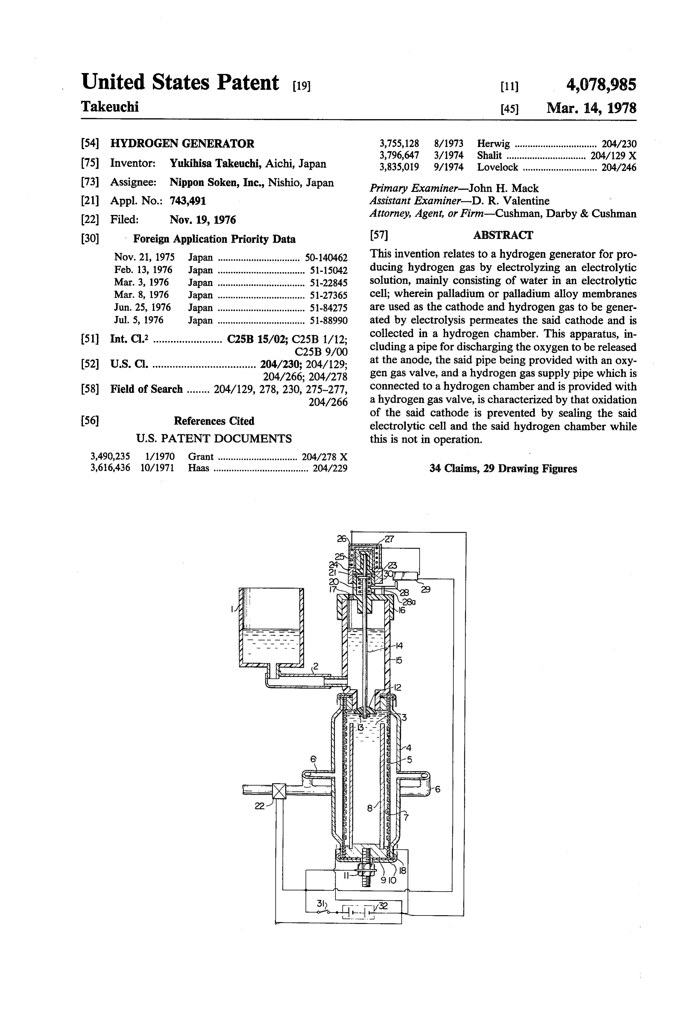
United States Patent (19) 11) 4,078,985 Takeuchi 45 Mar. 14, 1978 54 HYDROGENGENERATOR 3,755,128 8/1973 Herwig ................................ 204/230 3,796,647 3/1974 Shalit ......... ... 204/129 X 75) Inventor: Yukihisa Takeuchi, Aichi, Japan 3,835,019 9/1974 Lovelock ............................. 204/246 73 Assignee: Nippon Soken, Inc., Nishio, Japan Primary Examiner-John H. Mack 21 Appl. No.: 743,491 Assistant Examiner-D. R. Valentine . 22 Filed: Nov. 19, 1976 Attorney, Agent, or Firm-Cushman, Darby & Cushman 30) Foreign Application Priority Data 57 ABSTRACT Nov. 21, 1975 Japan ................................ 50-140462 This invention relates to a hydrogen generator for pro Feb. 13, 1976 Japan ... ... 51-15042 ducing hydrogen gas by electrolyzing an electrolytic Mar. 3, 1976 Japan ... ... 51-22845 solution, mainly consisting of water in an electrolytic Mar. 8, 1976 Japan ... ... 51-27365 cell; wherein palladium or palladium alloy membranes Jun. 25, 1976 Japan ... ... 51-84275 are used as the cathode and hydrogen gas to be gener Jul. 5, 1976 Japan .................................. 51-88990 ated by electrolysis permeates the said cathode and is 51 Int. Cl? ........................ C25B 15/02; C25B 1/12; collected in a hydrogen chamber. This apparatus, in C25B 9/00 cluding a pipe for discharging the oxygen to be released 52 U.S. Cl. .................................... 204/230; 204/129; at the anode, the said pipe being provided with an oxy 204/266; 204/278 gen gas valve, and a hydrogen gas supply pipe which is 58) Field of Search ........ 204/129, 278, 230, 275-277, connected to a hydrogen chamber and is provided with 204/266 a hydrogen gas valve, is characterized by that oxidation (56) References Cited of the said cathode is prevented by sealing the said electrolytic cell and the said hydrogen chamber while
3,490,235 1/1970 Grant ............................... 204/278 X 3,616,436 10/1971 Haas..................................... 204/229 34 Claims, 29 Drawing Figures
Page 2
Drawing sheet — no readable text.
Page 3
Drawing sheet — no readable text.
Page 4
Drawing sheet — no readable text.
Page 5
Drawing sheet — no readable text.
Page 6
Drawing sheet — no readable text.
Page 7
Drawing sheet — no readable text.
Page 8
Drawing sheet — no readable text.
Page 9
Drawing sheet — no readable text.
Page 10
Drawing sheet — no readable text.
Page 11
HYDROGEN GENERATOR In view of the foregoing description, it is a general object of the present invention to provide a hydrogen
BRIEF SUMMARY OF THE INVENTION generator with a novel feature which eliminates the The present invention relates to a hydrogen genera above-mentioned disadvantages.
Another object of the present invention is to provide tor wherein hydrogen is produced, in the way of elec a hydrogen generator wherein the oxidation of the cath trolysis, and purified by means of palladium or palla ode can be prevented without an appreciable waste of dium alloy membranes forming a cathode, and particu electrical power.
larly to a hydrogen generator used for a gas indicator A further object of the present invention is to provide utilizing the purified hydrogen gas as a carrier to detect O a hydrogen generator wherein the cathode can be made unknown gases, or for a device utilizing the purified thinner so as to improve its performance and its manu hydrogen gas as a fuel.
There has been a well-known device for producing invention, there are providedtoathe facturing cost. According embodiments of this high purity hydrogen gas, in which, using palladium or an oxygen gas valve in the hydrogen supplygaspassage hydrogen valve and palladium alloy tube as a cathode, water is electrolysed 15 in the oxygen discharge passage, respectively, and and the to generate purified hydrogen gas. In such a well hydrogen valve is closed when the power supply is cut known device, hydrogen gas liberated at the cathode is off for the cessation of the electrolysis and the oxygen permeated through the wall of palladium tube, used as gas the cathode, having a wall thickness of about 150 u, fromvalve is closed after a predetermined time lapses the time when the power supply is turned off. The simultaneous with pressurizing the hydrogen gas up to 20 oxidation of the cathode without a waste of electric 5 to 8 atm. The hydrogen generator is so constructed that the anode made of nickel forms the exterior of the ispower is attained by so devising that the hydrogen gas diffused back through the cathode into the electro electrolytic cell, and the paradium alloy cathode, in the lytic solution. With the construction wherein a pair of cell, forms a hollow cylindrical tube opened at one end cathodes consisting of a pair of palladium or palladium and closed at the other end, having a wall thickness of 25 alloy membranes, more than 100 L. Since the purified hydrogen gas per positioned in such each a way made in the form of a plate are that a pair of membranes face meated through the wall of the palladium tube, has each other, and a pair of anode, each made in the form relatively large capacity in comparison with its con of a plate are placed between the said pair of cathode sumed capacity, the pressure of the purified gas natu membranes, it becomes not technically difficult to make rally tends to be increased. 30 a cathode having a uniform thickness in comparison However, the above said well-known gas generator with the form of the hollow cylindrical tube. As the has following disadvantages: cathode can be made thin in this way, the material re The activated palladium cathode is oxidized into quired is smaller and the performance in hydrogen per palladium oxide by oxygen which is released at the meability anode and dissolved in the electrolytic solution when 35 efficiency ishydrogengreater. And as the result, a low-cost high generator can be provided.
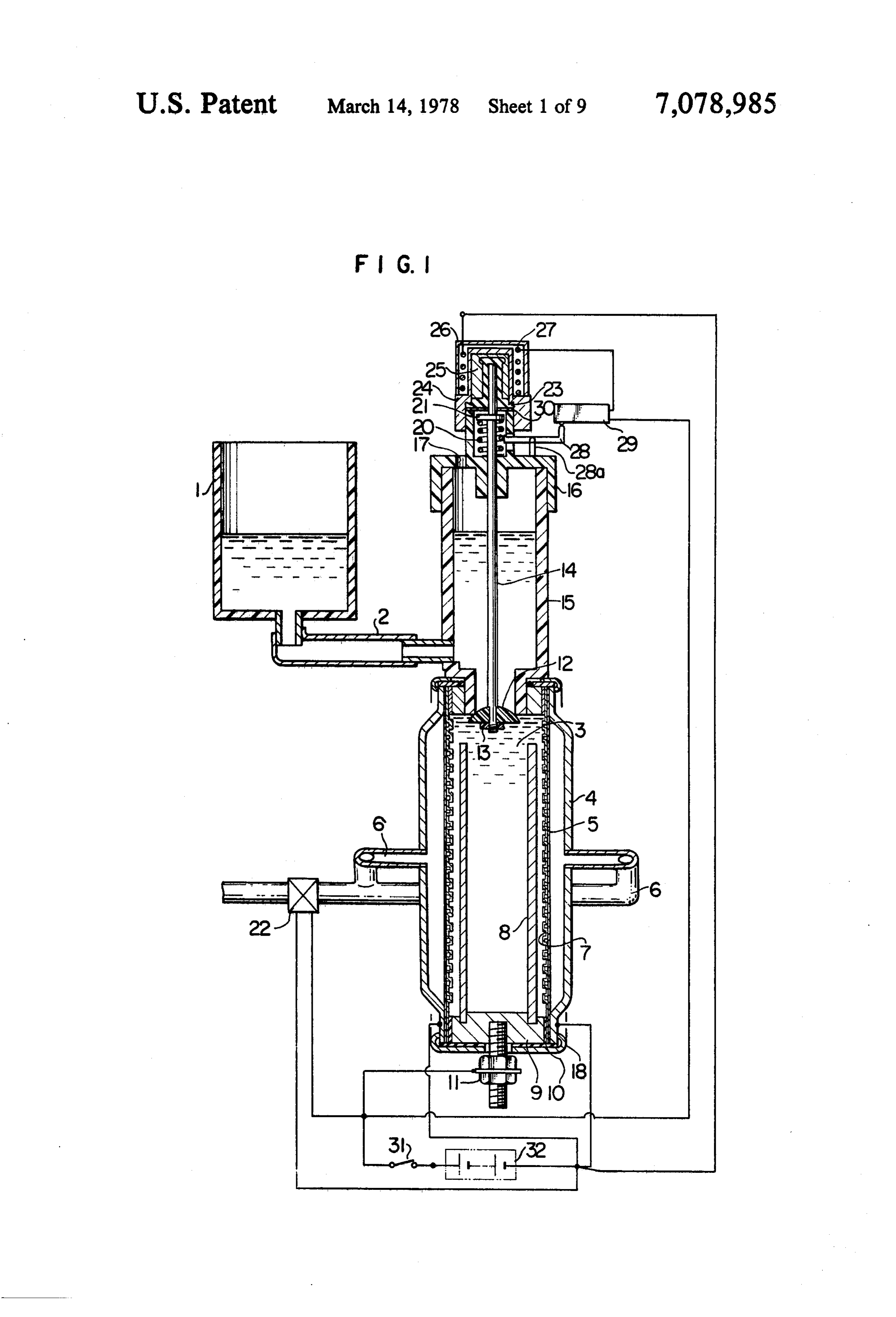
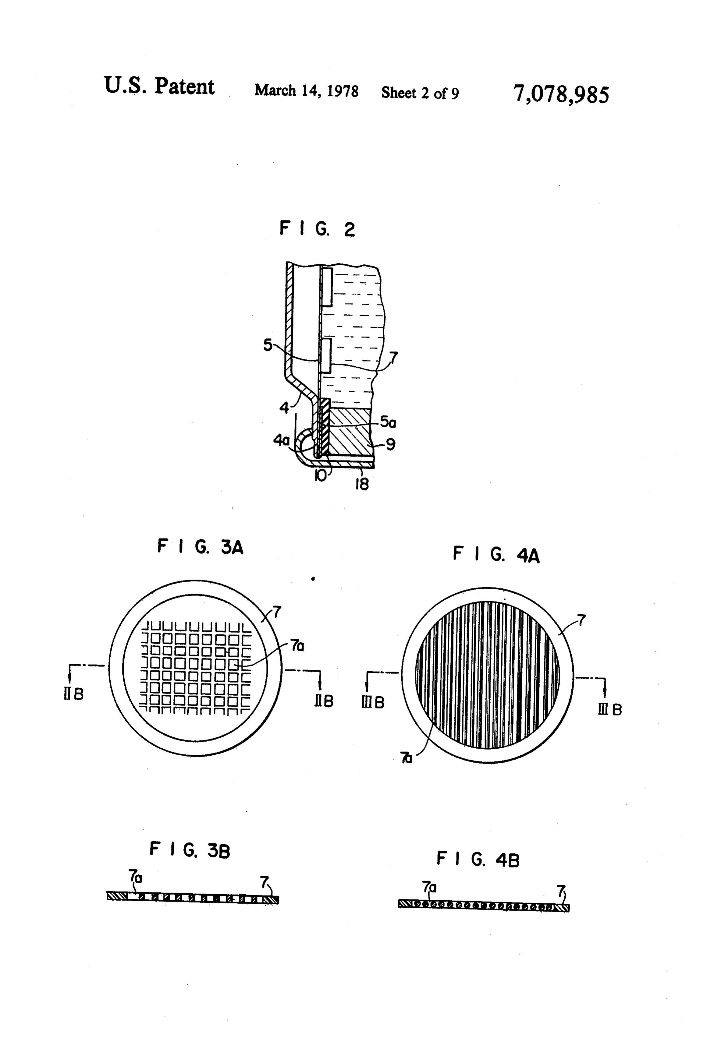
the generation of the hydrogen is stopped, or by other oxygen which exsists in the atmosphere and also dis BRIEF DESCRIPTION OF THE SEVERAL solves into the electrolytic solution. When the activated VIEWS OF THE DRAWING palladium or palladium alloy cathode is oxidized, the FIG. 1 is a schematic sectional view showing the capacity of producing the purified hydrogen gas structure through the wall of palladium tube cathode, is remark tion. of the first embodiment of the present inven ably lowered. In order to prevent the palladium or palladium alloy cathode from being oxidized, in the tiveFIG. 2 is a partial sectional view showing an alterna means for joining the case plate to the cathode.
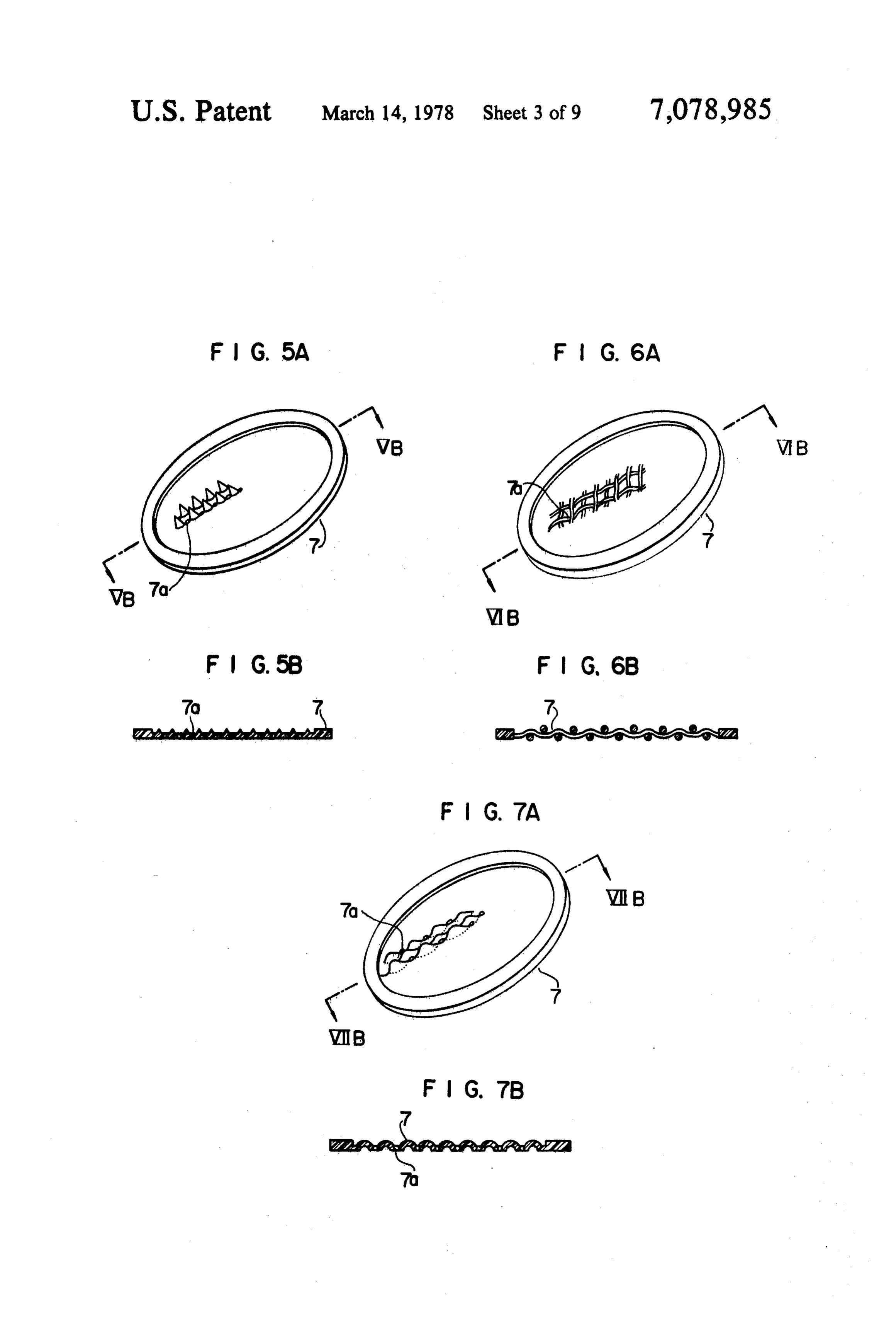
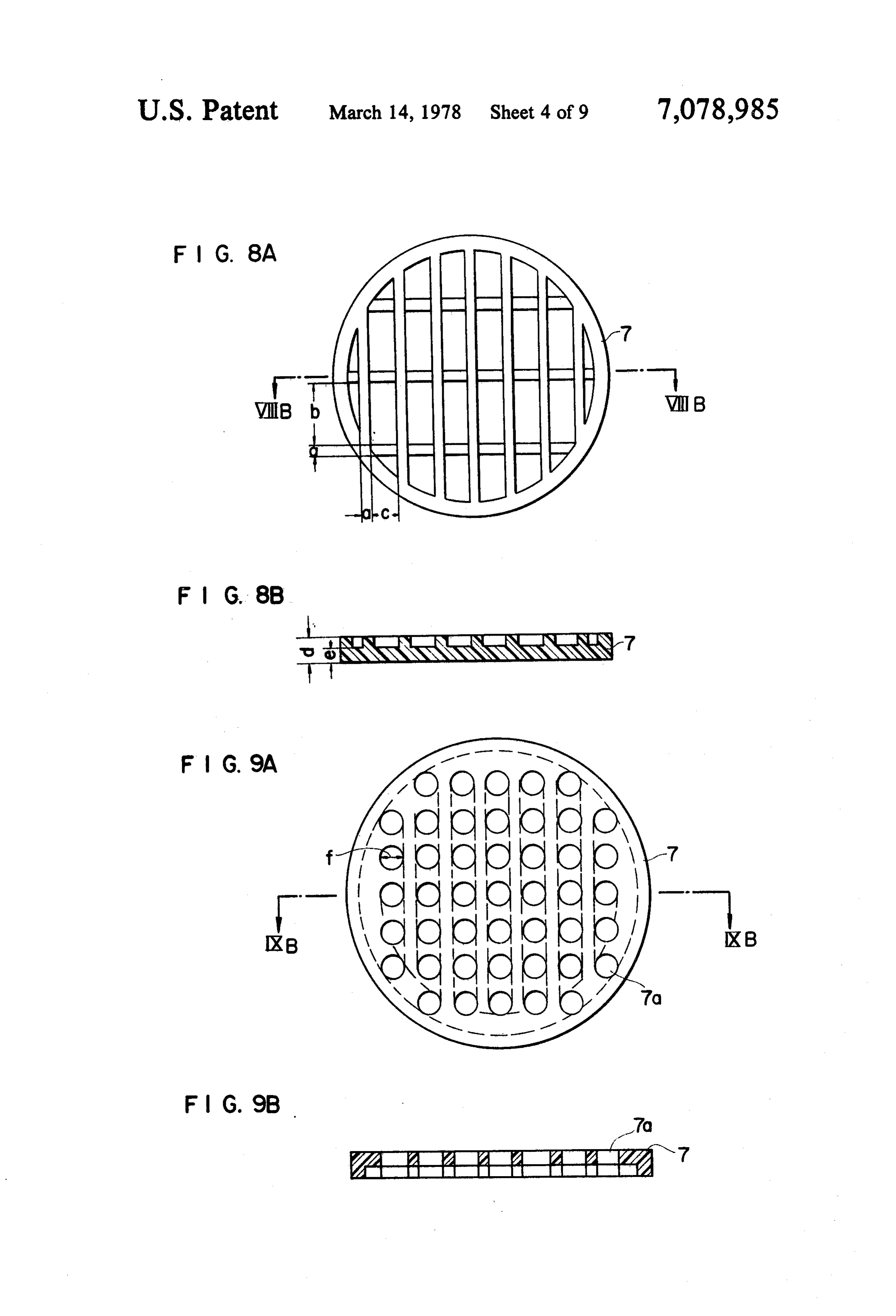
well-known hydrogen generator, by continuous energi FIG. 3A through FIG. 9A are schematic views zation between the cathode and the anode, the palla 45 showing reinforcement plates. dium or palladium alloy cathode should be held in the FIG. 3B through FIG.9B are sectional views thereof state that the cathode absorbes the hydrogen so enough taken along the lines in the respective views mentioned to react on the oxygen dissolving in the electrolytic above.
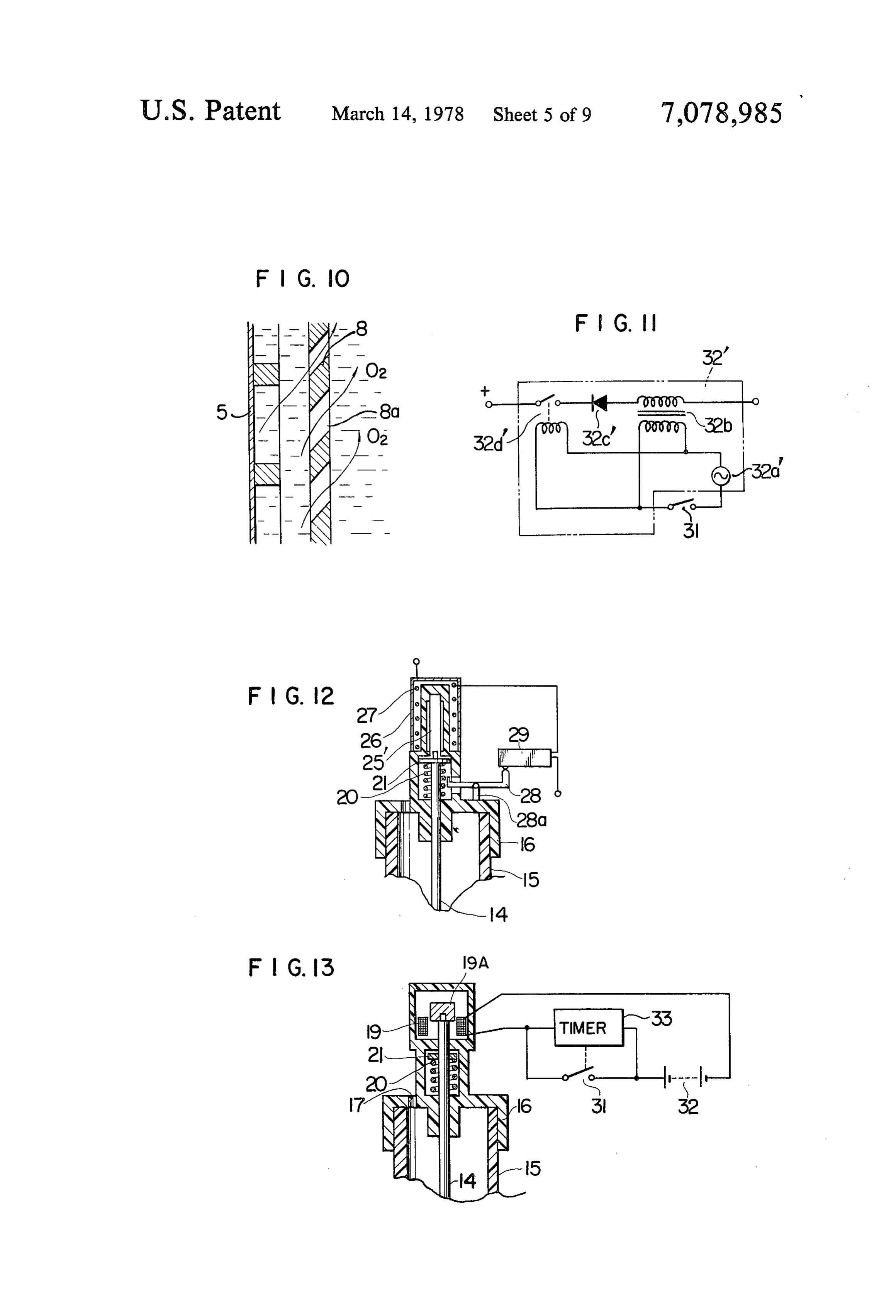
solution. But such continuous energization dissipates FIG. 10 is a partial enlarged view illustrating a modi electrical power. Further, since the anode made of 50 fication of the anode.
nickel forms the exterior or the outer casing of the FIG. 11 is a partial enlarged view showing a modifi electrolytic cell, the large amount of nickel material is cation of the power supply.
required, which causes the hydrogen generator to be expensive. Whenever the hollow cylindrical tube made ing modifications ofFIG.
FIG. 12 through 16 are schematic views show oxygen gas valves.
of palladium or palladium alloy material is used as the 55 FIG. 17 is a schematic view showing the all-over cathode arranged in the electrolytic solution, the cylin structure of the second embodiment in accordance with drical tube must have the wall thickness of about 150 L this invention.
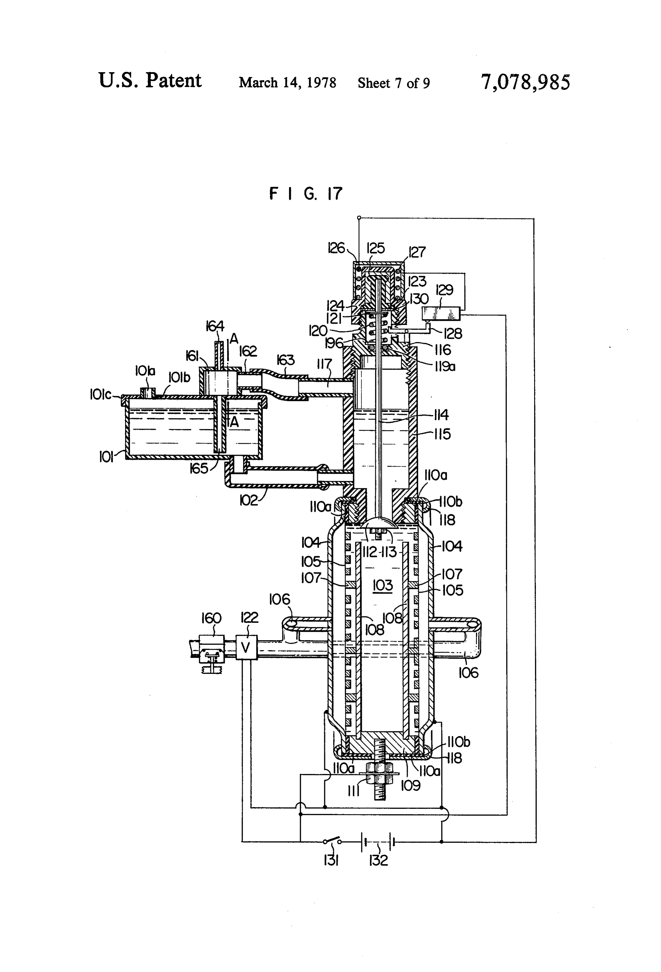
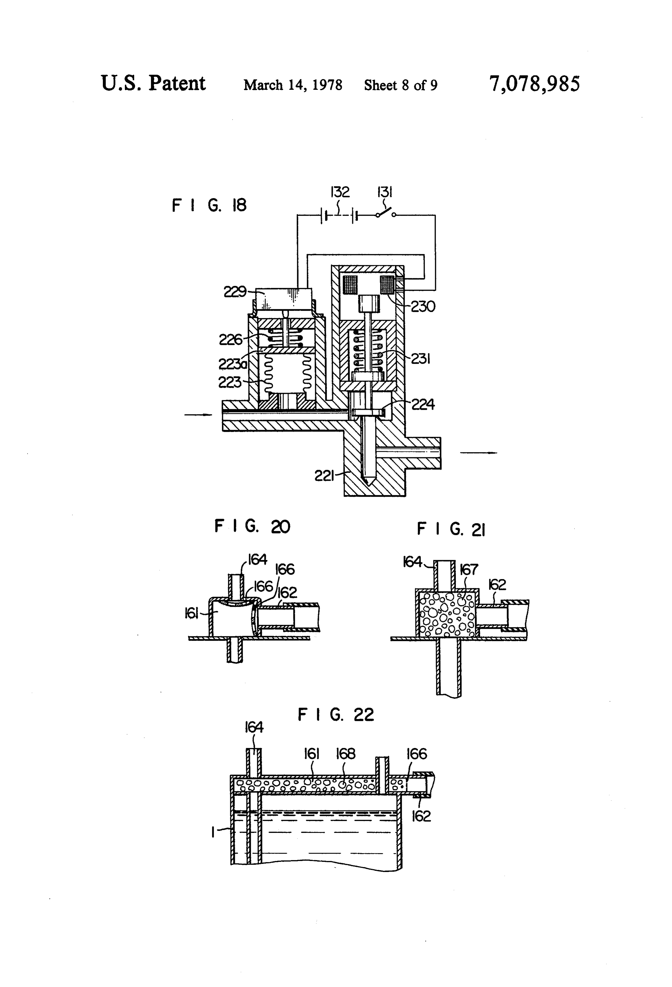
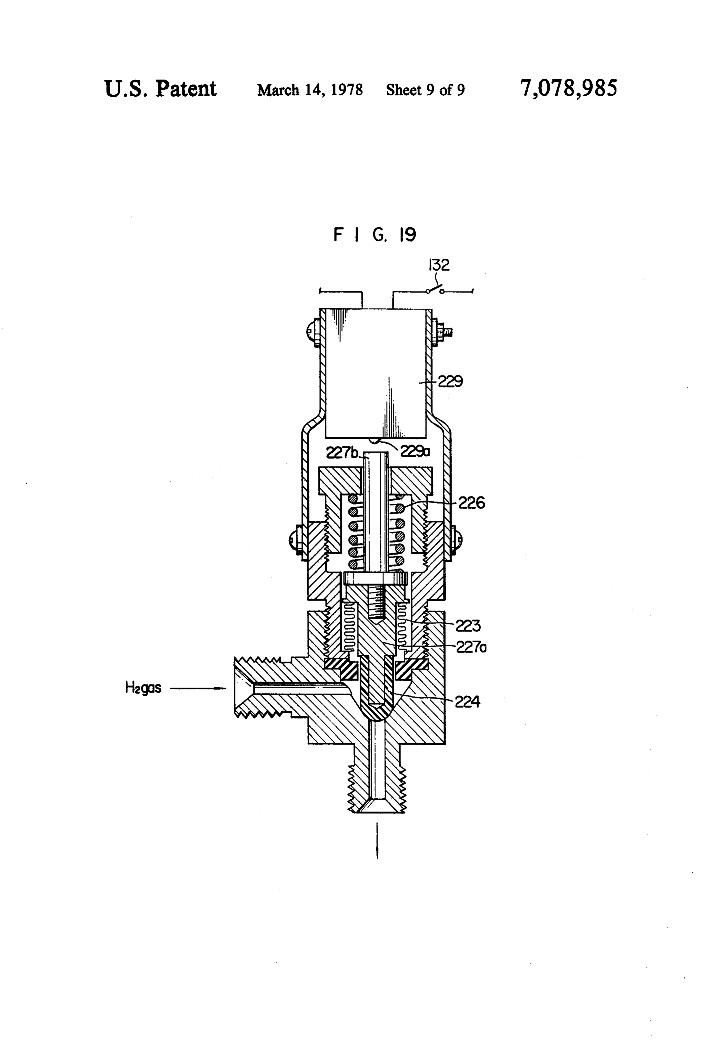
from both economical and functional view points. To FIG. 18 is a schematic view showing the structure of purify the hydrogen the thinner the wall thickness of a hydrogen gas valve. FIG. 19 is a modification thereof. the cylindrical tube, the better its capacity of producing 60 FIG. 20 through FIG. 22 are schematic views illus the purified hydrogen through the wall of the tube. trating examples of the bubble vanishing chambers. However, the proof-pressure of the tube is decreased, as the thickness of the tube wall is thined. It is to be noted DETALED DESCRIPTION that the proof pressure should be 5 to 8 atm. Besides, it is difficult to make a uniform tube of less than 100 u in 65 reference to theinvention
The present will be explained in detail with embodiments illustrated in the draw wall thickness in practice. For these reasons described ings. In the first embodiment shown in FIG. 1, storage above, the wall of the tube should be greater than a tank 1 for storing electrolytic solution is made of a predetermined value at the expense of its performance. plastics such as polyvinyl chloride and is connected to
Page 12
the main hydrogen generator with a connecting pipe 2, a form having spinous protrusions as shown in FIG. 5A through which electrolytic solution is supplied to the and FIG. 5B, a network as shown in FIG. 6A and FIG. generator. The electrolytic solution is pure water (dis 6B and complex waves as shown in FIG. 7A and FIG. tilled water) to which 20% by weight NaOH is added 7B. They all have a round frame and through-holes. for adjustment. It may be adjusted by KOH or a high Further, as shown in FIG. 8A and 8B, a double-decked purity NaCl as well. lattice-work in which the thickness of horizontal strips A case plate 4 in the main structure is of a disk shape differ from that of vertical stripping preferable. It is or a round dish shape and is made of stainless steel. A preferable, for various reasons, for example, for utiliz pair of case plates 4 are positioned on the sides of a ing as much surface area as possible of the cathode 5 and stainless steel ring 9 to make up a cylindrical body (its O keeping the distance between the cathode 5 and the axis extends in the horizontal direction in FIG. 1). anode 8 substantially constant, etc., that the width a of A cathode 5 consists of a pair of hydrogen permeative the lattice strip is more than 1 mm, the distance b plusc palladium or palladium alloy flat membranes, each is 2 mm S b + c S 80 mm, the thickness d5 mm or less welded to inside of the respective case plate 4, and and the thicknesse 1 - 3 mm. A double-steps construc positioned in such a way that they face each other in the 15 tion which has a plurality of round shaped through cylindrical body. It is preferable that the areas of those holes 7a as shown in FIG. 9A and FIG. 9B may be also portions of the cathode 5 and anode 8 facing each other used. Here the diameter fshould preferably be 1 mm is are substantially equal and the respective gap between fs 35 mm. Metal rods may be used as a core material. the cathode 5 and anode 8 are made also substantially These rods may be covered with polytetrafluoroethyl the same. It is also desirable that the anode 8 may have 20 ene or polyvinyl dichloride and fixed to the round shape a plurality of slant holes 8a as shown in FIG. 10 for frame of plastics. In this case, the thickness of the coat better discharge of oxygen gas to be produced on the ing may preferably be more than 10 micron. Metal lat surfaces of the anode 8. In order to obtain rigid welding tice-works or nettings may also be used instead of metal of the cathode 5 to the case plate 4, the cathode 5 is held rods.
between the case plate 4 which is made thinner at its 25 Coming back to FIG. 1, the cathodes 8 consist of a edge 4a and a reinforcement ring 5a made of the same pair of nickel membranes in the form of a disk which are material as the case plate 4 as shown in FIG. 2. The less so positioned that they face each other in the electro difference between the thicknesses of the edge 4a and lytic cell and are welded to the stainless steel ring 9. 10 the reinforcement ring 5a the better the welding rigid is a ring-shaped insulator made of a plastics material ity. A pair of membranes of the cathode 5 together with 30 such as polyethylene, polyester, P.T.F.E., etc. The case the ring 9 define a electrolytic cell 3 to be filled with plate 4 and ring 9 fixed with cathode 5, while holding electrolytic solution. The each cathode 5 also defines a the edge of the reinforcement 7 and insulator 10 be hydrogen chamber together with the corresponding tween them are fastened by the cylindrical ring 18 from case plate 4. When a palladium alloy is used as the cath outside. A terminal 11 which is connected to the plus ode 5, its composition may be approximately 30% palla 35 terminal of a D.C. power supply 32 via a power supply dium and the balance being made of any one or a mix switch 31 is screwed into the ring 9 for applying a volt ture of two or more elements selected from the group age to the anode 8. The minus terminal of the power consisting of copper, silver, gold, platinum and rho supply 32 is connected to the case plate 4 for applying dium. voltage to the cathode 5. As for the D.C. power supply, The cathode 5 can be made as thin as 2 - 100 microns as shown in FIG. the household or industrial A.C. because it was made flat. With a thickness of less than 2 power supply 32a' transformed down to 2-2.5 volts by microns, however, it was found to be unable to with an A.C. transformer 32b' and rectified by a diode 32c' stand 5-8 atm. pressure which is subjected at the time may serves the purpose.
of producing purified hydrogen. Here, when the primary circuit including the power Supply pipes 6, fixed and connected to both sides of 45 supply 32a' is cut off by the power supply switch 31, the case plates 4 guide the hydrogen gas that has been pro secondary circuit including the diode 32c' should also duced through the cathode 5. Provided on the internal be disconnected with a relay 32c'.
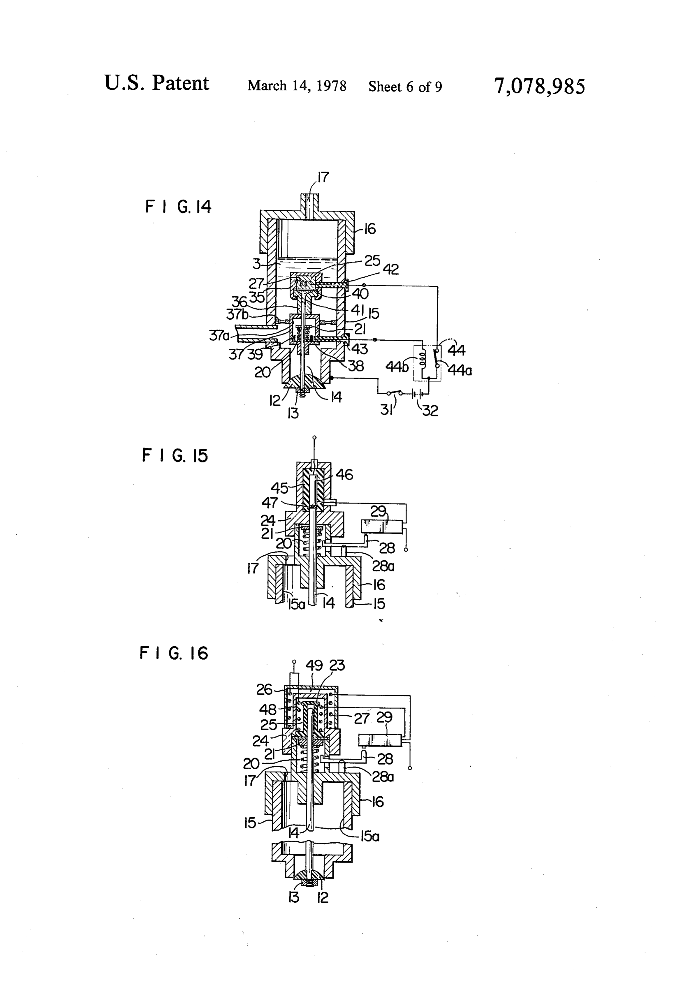
surface of the cathode 5 is a reinforcement 7 which can Next, an oxygen gas valve for discharging oxygen gas allow passage of electrolytic solution and hydrogen gas. will be explained. In the top portion of the ring 9 is This reinforcement 7 is for the protection of the cathode 50 provided a hole for oxygen discharge, and into this hole 5 from the pressure on it during the produce of the a pipe 15 made of P.V.C. for the passage of escaping purified hydrogen. With the use of reinforcement 7, the oxygen is inserted. A plastics valve 12 is disposed at the thickness of cathode 5 may be further reduced. The lower end of pipe 15 and is fixed to a shaft 14 with a nut reinforcements 7 which define the side surface of elec 13. The pipe 15, being connected with the aforemen trolytic solution are held between cathode 5 and insula 55 tioned connecting pipe 2, also serves as the electrolytic tor 10. The reinforcement 7 should be made of a mate solution supply passage. Over the top of the pipe 15 is rial impurities of which are not dissolved into the solu put a plastics cap 16 provided with an oxygen discharge tion when they deteriorated during the electrolysis of outlet 17 for discharging the oxygen gas into the atmo water such as polyacetal, polytetrafluoroethylene, poly sphere and with a bearing for the shaft 14 in the central ester, etc. When the cathode 5 is more than 30 micron in 60 portion. A valve drive unit for driving the oxygen gas thickness, the reinforcement 7 is required at least on the valve is provided in the upper portion of the cap 16. In side of electrolytic solution or the inside surface but the valve drive unit is a coil spring 20 which is disposed when it is less than 30 micron, an additional reinforce between the cap 16 and the flange 21 of the shaft 14 and ment (not shown in the drawing) is required on the side gives a biasing force to close the valve 12. A rubber of the hydrogen chamber, that is at the outside surface 65 sleeve 23 is fitted over the top end of the shaft 14. The thereof too. The reinforcement 7 may be made in vari space between this sleeve 23 and case 24 is filled with a ous forms: a lattice-work as shown in FIG. 3A and FIG. wax 25 which changes in volume with temperature. A 3B, a striped grating as shown in FIG. 4A and FIG. 4B, nichrome wire 27 for heating the wax 25 is wound
Page 13
around the case 24 and is covered with the case 26. It pressure high purity hydrogen which is fed through the has a limit switch 29 which is operated by the flange 21 pipe 6 to a suitable device where it is required. Upon through an L-shaped lever 28 when the shaft 14 is switching off the power supply switch 31 to cut off the moved beyond a predetermined stroke. The lever 28 is power supply to the cathode 5 and the anode 8, the supported by a fulcrum 28a disposed on the cap 16. hydrogen gas valve is closed concurrently and the Although not shown in the figure, it is a good practice power to the nichrome wire 27 is also cut off. The oxy to place an insulating material such as ceramic wool gen gas valve 12, however, remains opened till the between the nichrome wire 27 and the case 26 and to thermowax 25 which has been heated with the ni seal the nichrome wire 27 with a protective tube made of polytetrafluoroethylene, silicone rubber or other 10 chrome wire 27 cools off. Therefore, the oxygen gas material for the prevention of hydrogen explosion. The In this way it isafter valve is closed
the lapse of a predetermined time.
deviced that the hydrogen gas valve nichrome wire 27 is connected to the power supply 32 22 closes the hydrogen supply via the power supply switch 31 and limit switch 29 and the cease of the electrolysis pipe of 6 concurrently with the solution and the is fed with electrical current when both switches 2 and oxygen gas valve closes the passage 31 are turned on. A stay 30 disposed between the sleeve 15 oxygen a little while later than the time for the escaping 23 and the flange 21 is for the support of sleeve 23. A The hydrogen in the supply pipe 6, therefore, of the cease. hydrogen valve 22 provided in the supply pipe 6 is an back through the cathode 5 into the electrolytic diffuses ordinary electromagnetic valve which opens when the solu power supply switch is on, and closes when the switch tion and keeps the cathode 5 in the state of occluding hydrogen. Thus, the inverse diffusion of the hydrogen is off.
The position of the hydrogen gas valve 22 should be into the electrolytic solution increases the pressure in determined as follows: side the cathode 5 (on the part of the electrolytic solu Let V cc be the volume combining the volume of the tion) and gradually eliminates the pressure differential, hydrogen chamber, defined between the case 4 and the thereby bringing it to an equilibrium. Under this equilib pair of cathodes 5, and that of the supply pipe 6 from the 25 rium, the hydrogen that has diffused back and the oxy hydrogen chamber to the hydrogen gas valve; and let S gen existing in the electrolytic solution in part react to cm be the total surface area of the pair of the cathodes form water. This reaction destroys the above-men 5, tioned equilibrium and the hydrogen in the supply pipe the ratio V/S = 0.35 cc/cm.
resumes the inverse diffusion through the cathode 5 into 30 the electrolytic solution to produce a new equilibrium.
This is for attaining an effective prevention, to be de The repitition of this process gradually reduces the oxygen in the electrolytic solution into water. The scribed later, of the cathode from oxidation.
Now the mode of operation of the apparatus having amount of reaction of oxygen and hydrogen at the sur the above-mentioned structure is explained in detail. 35 electrolyticcathode face of the 5 decreases as the temperature of the solution decreases. Even if there remains
When the power supply switch 31 is turned on and oxygen that has not reacted electricity is applied to the cathode 5 and the anode 8, trolytic solution under roomupon hydrogen in the elec temperature, the oxidation for electrolysing the solution filled in the cylindrical body inside the cathode 5 oxygen gas is released at the of the cathode 5, i.e., the palladium membranes, hardly anode 8 and hydrogen gas is produced at the cathode 5. occurs due to the fact that the cathodes 5 always oc Upon switching on the power supply switch 31, the cludes hydrogen and that the speed of reaction between electrical current is also sent to hydrogen gas valve 22 oxygen and the cathode 5 is very slow at room tempera which immediately opens, and to the nichrome wire 27 ture. Besides, the greater part of oxygen in the electro for the operation of the oxygen gas valve. The oxygen lytic solution goes out into the atmosphere before the gas valve is operated as follows. When the thermowax oxygen gas valve is closed because of the fact that the 25 is heated by the nichrome wire 27, it expands and oxygen gas valve remains opened for a while after the moves the sleeve 23. The movement of the sleeve 23 is closing of the hydrogen gas valve 22 and further the transmitted through the stay 30 to the shaft 14 and inverse diffusion of the hydrogen in the supply pipe 6 pushes down the valve 12 and as the result the oxygen through the cathode 5 into the electrolytic solution gas valve opens. When the shaft 14 has travelled in a 50 helps discharging the oxygen into the atmosphere, and certain stroke, the flange 21 turns the lever 28 which in as the result, there remains only a very little oxygen turn pushes of the limit switch 29 and the power supply dissolved in the electrolytic solution in the cylindrical to the nichrome wire 27 is cut off. As the thermowax 25 body 3 when the oxygen gas valve has been closed. For cools off, the shaft 14 is pushed back by the coil spring instance, according to an experiment in which the oxy 20 by a little stroke upon which the limit switch 29 is 55 gen gas valve 22 was set to close 5-10 minutes after the turned on through the lever 28 and the power is sup plied to the nichrome wire 27 again to repeat the shaft switch 31 was turned off, and the hydrogen in the sup motion. The motion continues as long as the power is ode 5 had6 abetween ply pipe pressure hydrogen gas valve 22 and the cath of 4 atm. and a volume of 50 cc, the supplied to the cathode 5 and anode 8, in other words, amount of oxygen dissolved in the electrolytic solution, it is repeated during the electrolysis of the solution, but at the temperature of 80 C, was since the valve itself moves only by a slightly partial 60 cc oxygen per 100 cc electrolytic reduced solution
stroke, the communication of the pipe 15 and cylindri oxygen per 100 cc electrolytic solution. The cal body is normally maintained. As the hydrogen gas the hydrogen in the supply pipe 6 between pressure the hydro
valve 22 and the oxygen gas valve are open during the electrolysis of the solution, the oxygen comes through a gen gas valve and the cathode 5 was down to 1.5 - 2 gap or clearance between the valve 12 and the pipe 15 65 atm. after the lapse of 5-10 minutes. When the oxygen up the pipe and goes out into the atmosphere through gas valve 12 was closed after the lapse of 5-10 minutes, the discharge outlet 17. On the other hand, the hydro its pressure was maintained at 1.0 - 1.5 atm. and the gen permeates the cathode 5 and refines into a high pressure of electrolytic solution, on the other hand,
Page 14
being approximately 1.0 atm., the cathode 5 was kept in case 37 which forms a chamber 37a. The case 37 which the state of occluding hydrogen. is supported to a metal case 125 with a metallic plate 37b Here the desirable opening and closing time of oxy having holes. A tip of a metallic wire 38 is exposed in gen gas valve will be described below. Unless the oxy the case 37 and is prevented from contacting a coil gen gas valve is opened within 60 seconds after the spring 20 by an annular insulator 39 provided in the case power supply switch has been turned on, the oxygen 37. 40 is a diaphragm which seals the wax 25 against a produced by the electrolysis and enclosed in the cham mediam 41 made of a semi-fluid material. 42 is an insula ber defined within the cathode 5 in the cylindrical bodytor insulating the nichrome wire 27 from the case 25. 43 adversely raises the pressure on the cathode 5 to 1.5 is also an insulator insulating the metallic wire 3 from atm. approximately and damages the cathode 5. If the 10 the case 15. 44 is a relay which controls the circuit oxygen gas valve closes within 5 minutes after the including the power supply and the nichrome wire 27. power supply switch has been turned off, the oxygen When the power supply switch 31 is switched-on to produced at the anode 8 can not be sufficiently dis feed the electrical current to the cathode 5, anode 8 and charged and if it does not close after a lapse of 10 min hydrogen gas valve, a circuit consisting of power sup utes, the temperature of the electrolytic solution that 15 ply 32, nichrome wire 27, case 35, guide case 36, case has been relatively high (70-80C) is cooled down by 37, plate 37b and case 15, is established via contact 44a more than 10 C and the amount of the oxygen dis of the relay 44, and the nichrome wire 27 generates heat solved in the electrolytic solution becomes greater than which makes the wax 25 expands. The expansion of the that decided in Henry's law and as the result the cath wax 25 moves the shaft 14 to open the oxygen gas valve ode 5 is oxidized. For the above reasons, the oxygen gas 20 12. As the shaft 14 moves, the flange 21 comes in valve should open with 60 seconds after the start of the contact with the tip of the metallic wire 38, establishing operation (after the power supply switch 31 has been a closed circuit consisting of power supply 32, exciting turned on) and should close during the time between 5 coil 44b of relay 44, metallic wire 38, flange 21, coil - 10 minutes after the operation of the apparatus is spring 20, case 37, plate 37b, and case 15. Then the stopped (after the turn-off of the power supply switch 25 exciting coil 44b puts off the contact 44a and cuts the 31). power supply to the nichrome wire 27. When the ni In order to satisfy the above-mentioned condition, chrome wire 27 is cooled and the shaft 14 is pushed though this depends on other conditions such as the backed by the spring force of the coil spring 20, the electric consumption of the nichrome wire, amount of flange 21 comes off the metallic wire 38 and puts on the wax and the amount of electrolytic solution, a ther contact 44a of the relay 44 and the nichrome wire 27 is mowax changing from a solid form to a liquid form at re-energized. This electrical on-off control for the ni the temperature of 100 C-10 C should be selected for chrome wire 27 is repeated during the electrolytic oper economical and practical reasons. ation, but the off-period of heating is such a short time The thermowax used here in this embodiment mainly that the valve 12 moves only by a small partial stroke consists of an ester of fat acids and insoluble high class 35 and therefore the oxygen gas valve is kept opened. monohydric or dihydric alcoholes and an ester of a fat When the power supply switch 31 is turned off, the acids and glycerin. A wax mainly consisting of montan power supply to the nichrome wire 27 is cut off. And as wax and a hydrocarbon, ozocerite occuring indepen the wax 25 cools down, the oxygen gas valve gradually dently in nature or a petroleum wax such as paraffin closes. In this example, the wax 25 is directly heated by wax, microcrystalline wax, petrolatum wax, etc. can the nichrome wire 27 and at the same time so devices as also be used for it. Instead of one kind of wax, a mixture to be warmed by the electrolytic solution. This shortens of two or more types of wax can be used as well. the time required for the opening of the valve at the Whichever wax it may be, the lowest temperature at start of the electrolysis, thereby preventing the cathode which it starts changing from a solid form to a liquid 5 from being damaged by the oxygen to be generated at form must be within 100 C - 40 C. Also as shown in 45 the anode 8 which would otherwise remain undis FIG. 12, a heat-sensitive member 25' consisting of a charged. FIG. 15 shows a further example in which a metal which has a high coefficient of thermal expansion metallic case 24 contains a nichrome bar 46 fit in an may be used instead of wax 25 to drive the oxygen gas insulation tube 45 and the end of the nichrome bar 46 is valve. The drive unit for the oxygen gas valve may be made into contact with the shaft 14 via an insulating also so constructed as shown in FIG. 13 that the D.C. 50 plate 47 made of, for example, ceramic material which power supply 32 continues to send electrical current to would not break under the compressive force, and is an electromagnetic coil 19 after the turn-off of the connected to the power supply via a limit switch 29. power supply switch 31 and the closed circuit of the This nichrome bar 46 expands as it heats itself and the D.C. power supply and the electromagnetic coil 18 is expansion is transmitted to the shaft 14. In this example opened (deenergized) by a timer 33 after the lapse of a 55 too, the opening time required for the oxygen gas valve predetermined time (for instance, 5-10 minutes) so that is decided in a similar way as described above. A still an iron core 19A in association with the coil 19 closes further example is shown in FIG. 16, which will be the oxygen gas valve through the shaft 14 by the spring explained below. The top end of the shaft 14 is fitted 20. Whenever lowering, more or less, in performance of over with a rubber sleeve 23. The space between the oxygen gas discharge is allowed, the oxygen gas valve 60 sleeve 23 and the case 24 is filled with wax 25 in which may be operated concurrently with the on-off of the a nichrome wire 48 is buried. A nichrome wire 27 is power supply switch 31, by eliminating the timer. wound around the case 24 and is protected by a heat FIG. 14 which shows another example of its modifi insulating material. The control of the electric power to cation will be explained. A case 35 made of a metal the both nichrome wires 27 and 48 is done by a limit having very high thermal conductivity is disposed in 65 switch 29. When the power supply switch 31 shown in the electrolytic solution 3. The case 35 encloses a wax the FIG. 1 is turned on, the power is fed via the limit 25 in which a nichrome wire 27 is embedded. A metallic switch 29 to the nichrome wires 27, 48, and the wax 25 guide case 36 for guiding a shaft 14 is fixed to a metallic expands in a very short time period and opens the oxy
Page 15
gen gas valve. When the oxygen gas valve has opened shaft 227a supporting the valve 224, comes into contact to a certain extent, allowing the oxygen which has been with the switch button 229a causing the micro-switch liberated by the electrolysis to go out into the atmo 229 to turn on and off. Although it is not shown in the sphere, the flange 21 of shaft 14 pushes the lever 28 figure the micro-switch 229 is connected in series with which in turn actuates the limit switch 29 to cut of the the power supply switch 131 and the power supply 132. power supply to the nichrome wire 48. The power to When the pressure of the hydrogen gas being supplied the nichrome wire 27, however, is still maintained and exceeds a predetermined amount, the shaft 227 pushes the shaft is further pushed down until the gap between the button 229a and turns off the switch 229 to stop the valve 12 and the case 15 becomes sufficiently wider, producing hydrogen. A regulator 160 is positioned in for instance, 5 - 6 mm, so as to discharge the further 10 front of the hydrogen gas valve to maintain the hydro amount of the oxygen into the atmosphere. At this gen at a constant pressure during the operation of the point, the lever 28 is pushed again and the limit switch apparatus.
29 breaks the circuit. As the wax cools down, the shaft When the valve 112 is opened, the oxygen to be liber 14 is pushed back by the spring force of the coil spring ated at the anode 108 goes up the oxygen discharge 20. When the gap between the valve 12 and the case 15 15 passage infine bubbles. A very small amount of organic become smaller than the above-mentioned 5-6 mm, the matters are mixed in the electrolytic solution. These limit switch 29 is operated via the lever 28 and closes organic matters and the electrolytes such as caustic soda the circuit to the nichrome wire 27. When the power react together and form a very small amount of soap. By supply switch 31 is turned off, the power supply to the the action of the soap, the oxygen tends to form a large nichrome wires 27 and 48 is broken and the wax 25 20 quantity of relatively large bubbles at the boundary starts to cool. After the lapse of a short time, the valve surface of the electrolytic solution and the atmosphere 12 closes tightly against the case 15. in the oxygen discharge passage. These bubbles are led Next the second embodiment in accordance with this to the bubble vanishing chamber 161 and disappear invention will be explained with main emphasis on the completely when they are pushed out into the chamber points which differs from the first embodiment shown 25 as the sectional area at Sec. A-A in the FIG. 17 is in FIG.1. In FIG. 17, two pieces of case plates 104 and larger than the sectional area of the inlet 162. The drops a ring 109, being insulated by a pair of insulating plates of water and the caustic soda (electrolytes) contained in 110a and an insulating ring 110b, are fastened together the drops which have been forming the bubbles are by means of a cylindrical case 118. A part of the lattice returned through the returnpipe 165 to the electrolytic work of the reinforcement plate 107 supporting the 30 solution tank 101, while the oxygen are released into the cathode 105 is made thicker so that it may contact the outer atmosphere through the release pipe 164. In this anode 108 and keep the distance between the cathode way, only oxygen are discharged into the outer atmo 105 and the anode 108 substantially constant. sphere. This not only prevents the apparatus from being A storage tank 101 is covered with a cup 101c having damaged by the bubbles containing caustic soda but a solution supply hole 101a and an air vent hole 101b. 35 eliminates the decrease in concentration of the caustic The cap 101c is provided with an air bubble vanishing soda in the electrolytic solution. When the return pipe chamber 161. This bubble vanishing chamber is for 165 is made relatively small in diameter and the bubble making disappear the bubbles which accompanys with vanishing chamber 161 is made relatively small in vol the oxygen gas to be discharged into the open air. The ume, for example less than 200 cc, an explosive combus inlet 162 to the chamber is connected with a pipe 163 to tion that might be caused by the reaction of the oxygen oxygen discharge pipe 117. The bubble vanishing cham and a small amount of hydrogen that is discharged to ber 161 has a release pipe 164 for releasing oxygen to gether with the oxygen would not be a problem. the atmosphere and a return pipe 165 for returning the The hydrogen gas, on the other hand, permeats the vaper which has condensed in the passage from oxygen cathode 5, and refines into a high pressure high purity discharge pipe 117 to the bubble vanishing chamber 45 hydrogen which is stored and compressed in the supply 161. The bubble vanishing chamber 161 is so made that pipe 106. When the pressure of the hydrogen in the the sectional area at Sec. A-A is larger than that of the supply pipe 106 exceeds a predetermined pressure inlet 162 and the volume is less than 200 cc. (which is preferably greater than the atmosperic pres As for the hydrogen gas valve 122, the pressure of the sure by more than 1 kg/cm, but may be a pressure hydrogen gas is utilized for the control of the electro 50 slightly higher than the atmospheric pressure as long as magnetic valve (See FIG. 18). The pressure of the hy that may cope against the pressure of the electrolytic drogen gas is detected with the expansion and contrac solution) determined by the spring 226 and bellows 223 tion of a bellows 223. The expansion and contraction of of the hydrogen gas valve, the valve 224 of the hydro this bellows operates a microswitch 229 via a plate 223a gen gas valve unit opens so as to open the passage for having a protrusion. The on and off of the micro 55 the hydrogen gas to be fed to a device where it is re switch, in addition to the on and off of the power supply quired. And when the pressure of the hydrogen falls switch, controls the power supply to the electromag below the predetermined pressure, the valve 224 of the netic coil 230 and operates the electromagnetic valve hydrogen gas valve unit closes and shuts off the supply 224. pipe 106. The use of the bellows 223 for the detection of From the logical consequence that the pressure of the the hydrogen pressure enables the hydrogen gas valve hydrogen gas drops with the turn-off of the power to act sharply at the predetermined pressure. The con supply switch, the electromagnetic valve is not particu trol of the hydrogen pressure with hydrogen gas valve larly necessary. The expansion and contraction of the during the operation of the apparatus in this way pre bellows 223 which detects the hydrogen pressure, may vents dislocation, deformation and breakage of the cath directly operates a valve for the purpose. (See FIG. 19.) 65 ode 105. When the power supply switch 131 is turned In this case, a spring 226 gives a valve closing force to off, breaking the circuit to the cathode 105 and anode the valve 224 and the valve seat is in the conical shape, 108 for stopping the operation of the apparatus, the and a shaft 227b which is connected to the top of the electric current to the wire 127 stops and the coil spring
Page 16
129 pushes back the valve 112 tightly against the end of time, and to prevent the hydrogen gas contained in the pipe 115, thereby closing the oxygen gas valve. said hydrogen chamber from discharging through With the turn-off of the switch 131, the hydrogen gas the electrolyte and said discharge pipe. valve 122 is also closed. With the closing of the both 2. An apparatus as claimed in claim 1 further compris valves, oxygen gas valve 112 and hydrogen gas valve 5 ing a storage tank connected to said discharge pipe for 122, the cell inside the case plates 104 is kept under storing the electrolyte to be supplied to said electrolytic sealed condition. cell.
Thus, the cathode 105, i.e., the palladium membranes, 3. An apparatus as claimed in claim 1, wherein said are kept being pressuring even after the cease of the hydrogen gas valve opens and closes said hydrogen operation, and therefore, the reinforcement 107 does 10 supply pipe in response to the pressure of hydrogen gas not become detached from the palladium membranes in said supply pipe when said power supply switch is and protects the palladium membranes from the possi closed.
ble damages. Also as described previously, upon closing 4. An apparatus as claimed in claim 1, wherein said the hydrogen gas valve 122, the hydrogen gas in the hydrogen gas valve includes a second switch connected supply pipe 106 diffuses back through the cathode 105 15 in series with said power supply switch for control of into the electrolytic solution. For this, the oxygen gas in the power supply to said electrolytic cell in response to the electrolytic solution goes out into the atmosphere the pressure of the hydrogen when said power supply and there remains only a very little oxygen dissolved in switch is closed.
the solution. The oxidation of the cathode during the 5. An apparatus as claimed in claim 1, wherein said cease is avoided in this way. 20 valve unit comprises:
Further, it is a good and effective idea to provide the a valve head cooperative with said outlet hole of said bubble vanishing chamber 161 with a net made of a electrolytic cell at which outlet hole said discharge material such as nickel, Teflon, or polyvinyl chloride as pipe is connected;
shown in FIG. 20 or to enclose fibers 167 such as ce valve drive means having a thermal expansive mate ramic fibers, nickel fibers, Teflon or polyvinyl chloride 25 rial a shaft connected said valve head so as to drive fibers as shown in FIG. 21. It will expedite vanishing of said valve head in accordance with thermal expan the bubbles and quickly extingish the flames in case the sion of said expansive material, and a heating wire oxygen and hydrogen should accidentally react each connected to said power source through said other by shock. Also the bubble vanishing chamber may power supply switch for heating said expansive be made larger than 200 cc by providing grains 168 of 30 material;
alumina, nickel, Teflon, or P.V. C. in the chamber. With said valve head opening said outlet hole when said this, an efficient cooling of the bubbles containing oxy expansive material is expanded; and closing the gen and an effective recovery of the condensed solution same when said expansive material is contracted. can be made concurrently with the vanishing of bubbles 6. An apparatus as claimed in claim 1, wherein said and the avoidance of explosion. 35 valve unit opens said discharge pipe within 60 seconds What is claimed is: after said power supply switch is closed. 1. A hydrogen generating apparatus for producing 7. An apparatus as claimed in claim 1, wherein said hydrogen gas by decomposing an electrolyte consisting valve unit closes said discharge pipe within 5 to 10 mainly of water, comprising: minutes after said power supply switch is opened. a. an electrolytic cell for containing the electrolyte, 40 8. An apparatus as claimed in claim 1 further compris said cell having an anode and a cathode made of 1ng:
gas permeable palladium or palladium alloy; a bubble trapping chamber connected to said dis b. an electric power source electrically connected charge pipe for removing bubbles formed by the across said anode and cathode for supplying elec generated gas.
tric power to said electrolytic cell through said 45 9. An apparatus as claimed in claim 8, wherein said anode and cathode to electrolyze the electrolyte bubble trapping chamber is provided with a net. therein; 10. An apparatus as claimed in claim 8 wherein said c. a power supply switch for on-off control of the bubble trapping chamber is filled with fibers. power supply from said power source to said elec 11. An apparatus as claimed in claim 8, wherein the trolytic cell; 50 volume of said bubble trapping chamber is less than 200 d. a discharge pipe connected to an outlet hole of said CC.
electrolytic cell for discharging oxygen gas pro 12. An apparatus as claimed in claim 8, wherein said duced at said anode; bubble trapping chamber is filled with grains of a mate e. a hydrogen chamber formed in the vicinity of said rial selected from the group consisting of alumina, gas permeable cathode for collecting hydrogen gas 55 nickel, Teflon and polyvinylchloride.
electrolytically produced thereat; 13. An apparatus as claimed in claim 1, wherein said f, a hydrogen supply pipe connected to said hydrogen electrolytic cell comprises;
chamber for supplying the hydrogen gas; an electrically conductive ring; g. a hydrogen gas valve connected to said supply a pair of circular and flat membranes made of palla pipe, for closing the same to stop the supply of said dium or palladium alloy foring said cathode, said hydrogen gas when said power supply switch is pair of membranes being disposed at both ends of opened; and said ring to form a cavity therebetween for con h. a valve unit connected to said discharge pipe, for taining said electrolyte;
closing said discharge pipe when a predetermined insulating means disposed between said ring and said time has elapsed after the cessation of the power 65 pair of membrane for electrically insulating said supply to said electrolytic cell so as to discharge a membranes from said ring; and substantial amount of said oxygen gas through said a pair of plates disposed in said cavity and electrically discharge pipe during the predetermined elapsed connected to said ring to form said anode, each of
Page 17
said plates facing each of said flat membranes at a 21. An apparatus as set forth in claim 20, wherein a predetermined distance. reinforcement is provided between said cathode plates 14. An apparatus as claimed in claim 13, further com and said ring for reinforcing said cathode plates. prising a pair of dish-shaped case plates, each such plate 22. An apparatus as set forth in claim 21, wherein said being fixed to the outside of said membranes to form reinforcement is in the form of a round lattice-work said hydrogen chamber. frame.
15. An apparatus as claimed in claim 13, further com 23. An apparatus as set forth in claim 21, wherein said prising a reinforcement fixed to the inside surface of reinforcement is in the form of a round net frame. said membrane for reinforcing said membrane. 24. An apparatus as set forth in claim 22, wherein a 16. An apparatus as claimed in claim 15, wherein said 10 part of said lattice-work is in contact with said anode reinforcement is in the form of a lattice-work. plates keeping a space between said cathode and the 17. An apparatus as claimed in claim 15, wherein said anode substantially constant.
reinforcement is in the form of a net. 25. An apparatus as set forth in claim 19, wherein a 18. An apparatus as claimed in claim 13, wherein said storage tank, connected to said discharge pipe is further anode plate is provided with a plurality of slanted holes. 15 provided for both storing said electrolytic solution and 19. A hydrogen generator for producing hydrogen supplying said solution from said tank to the electrolytic gas by electrolyzing an electrolytic solution mainly cell.
consisting of water, comprising; 26. An apparatus as set forth in claim 25, wherein said a. a ring having electric conductivity, electrolytic solution has a cap upon which a bubble trap b. a cylindrical body made up to two pieces of case chamber is provided for trapping the bubbles to be plates having electric conductivity and placed, formed by oxygen gas.
under electrically insulated condition, on the both 27. An apparatus as set forth in claim 26, wherein said ends of said ring, chamber is provided with a net.
c. two pieces of cathode plate consisting of hydrogen 28. An apparatus as set forth in claim 26, wherein said permeative palladiumor palladium alloy mem 25 chamber is provided with granular particles. branes which are fixed to the inside surfaces of the 29. An apparatus as set forth in claim 19, wherein said case plates of said cylindrical body and are pinched hydrogen gas valve is operationally connected to said in between and electrically insulated from said ring power supply switch and is closed in response to the and form together with said ring the electrolytic turn-off of said switch.
cell to be filled with the electrolytic solution, 30 30. An apparatus as set forth in claim 19, wherein said . two pieces of anode plate fastened to the surface of hydrogen gas Valve opens and closes in response to the said ring and positioned in such a way that each pressure of hydrogen gas and is closed when the pres plate faces said respective calice plate, sure of hydrogen gas becomes less than a predetermined e. a power supply electrically connected to said ring pressure.
and said case plates for impressing a voltage be 35 31. An apparatus as set forth in claim 30, wherein said tween said anode and cathode, hydrogen gas valve includes a second switch which is f, a power supply switch for making and breaking connected in series with said power supply switch and said electrical connection with said anode and cath is turned off when the pressure of the hydrogen gas falls ode, below a predetermined pressure, stopping said power g, a discharge pipe joined to the top of said ring for supply from impressing the voltage to said anode. discharging oxygen gas to be generated at said 32. An apparatus as set forth in claim 19 further com anode, prises a delaying means is provided for making said h. an oxygen gas valve unit, for controlling the dis oxygen gas valve unit close said oxygen gas valve after charge of the oxygen gas, provided with a valve the lapse of a predetermined time from the turn-off of which is located at the opening of said discharge 45 said power supply switch.
pipe to said electrolytic cell for sealing and opening 33. An apparatus as set forth in claim 19, wherein the of the electrolytic cell by opening and closing of valve actuator of said oxygen gas valve is provided said opening, and with a valve actuator which is with;
connected to said valve for actuating said valve to a. a thermal expansion means for expansion and con open and close, and is operationally connected to 50 traction in response to the heat to be impressed, said power supply switch to actuate said opening b. a connection means for connecting said thermal and closing in response to the on and off of said expansion means with said valve and for making switch, said valve make a return motion in response to the i. a hydrogen chamber formed in the vicinity of said expansion and contraction of said thermal expan cathode for collecting the hydrogen gas to be liber 55 sion means, ated at the cathode and to be purified after its per c. an additional switch which goes on and off with meation of the cathode, the return motion of said connection means, and is j. a supply pipe connected to said hydrogen chamber electrically connected in series with said power for supplying said hydrogen gas, and supply switch, and k. a hydrogen gas valve installed to said supply pipe 60 e. a means for supplying, in response to the on and off and is so arranged that it will open and close said of the power supply and said second switch, the supply pipe and will be closed when said supply electric power to said electric heating means. switch is turned off, whereby said electrolytic cell 34. An apparatus as set forth in claim 19, wherein a and the hydrogen chamber are sealed while said cap is further placed on the top of said discharge pipe hydrogen generator is not in operation. 65 and a valve actuator for said oxygen gas valve is pro 20. An apparatus as set forth in claim 19, wherein the vided on the cap and is connected with said valve by a above-said anode plates are provided with many slanted shaft disposed in said discharge pipe. holes for conducting the oxygen gas. is s
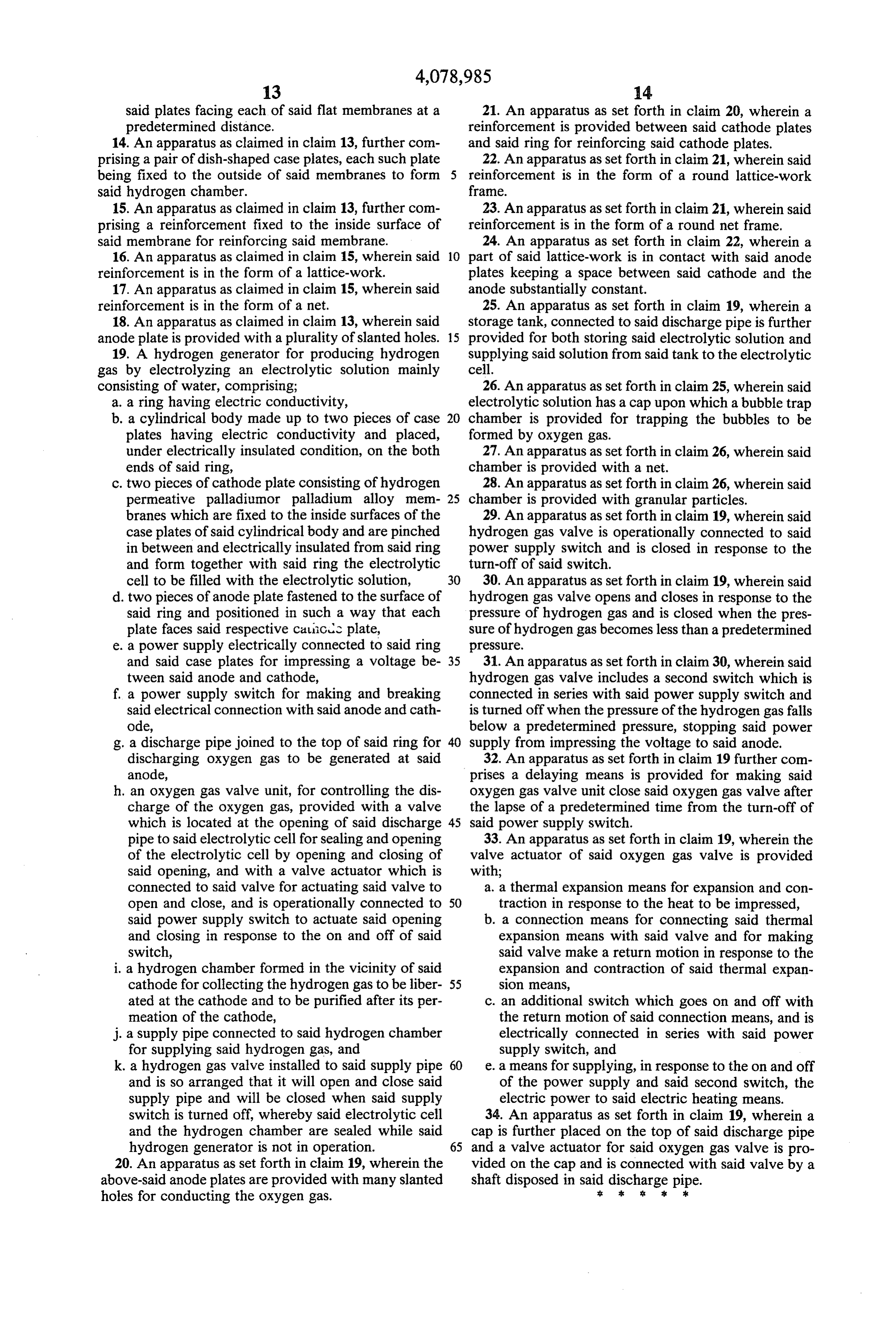
Page 18
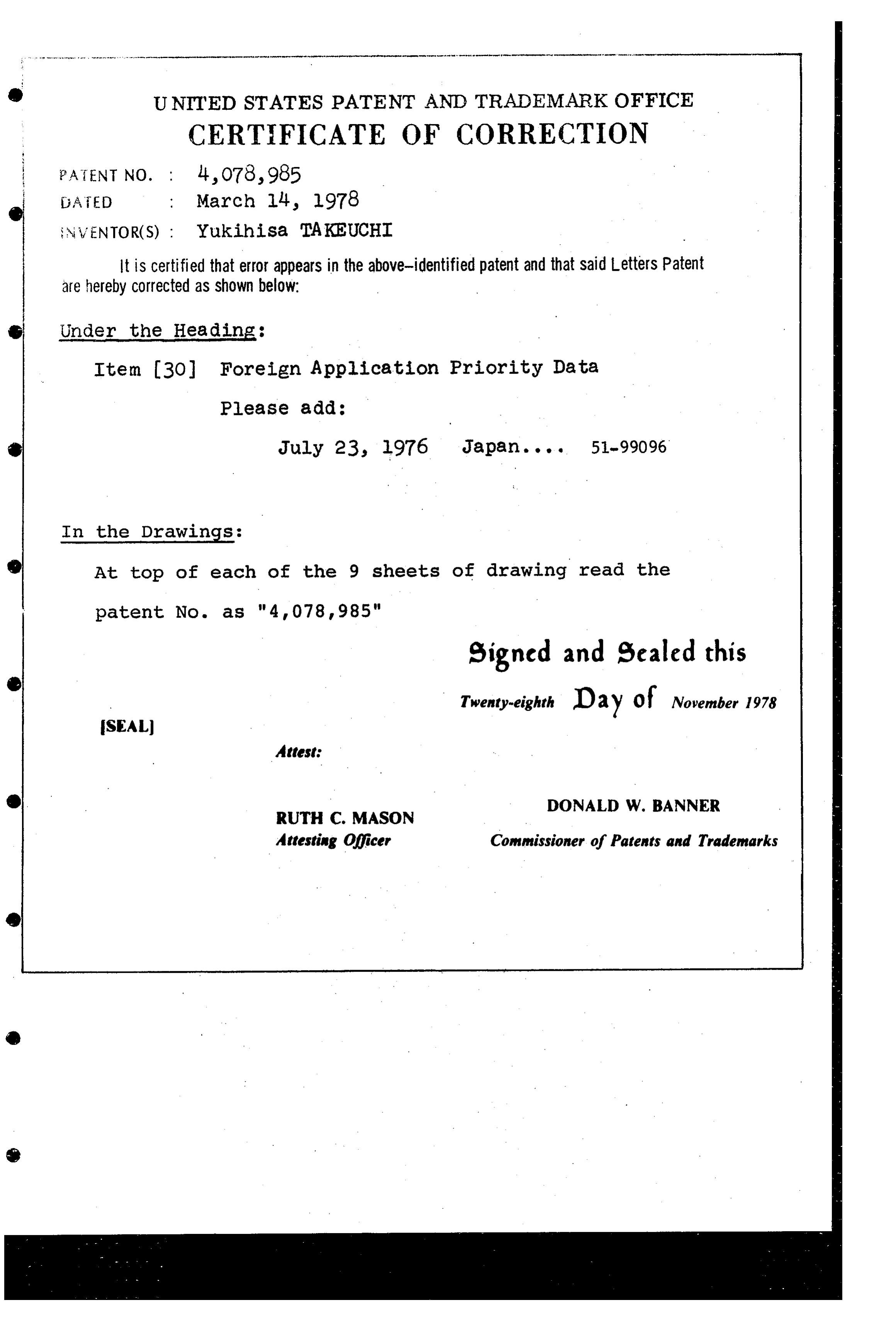
UNITED STATES PATENT AND TRADEMARK OFFICE
CERTIFICATE OF CORRECTION
NWENTOR(S) : Yukihisa TAKEUCHI
It is certified that error appears in the above-identified patent and that said Letters Patent are hereby Corrected as shown below: Under the Heading:
Item 3O Foreign Application Priority Data Please add:
In the Drawings:
At top of each of the 9 sheets of drawing read the
signed and sealed this
Twenty-eighth Day of November 1978
SEAL
Attest:
DONALD W. BANNER
RUTH C. MASON
Attesting officer Commissioner of Patents and Trademarks
Provenance
- Collection
- Cited prior art
- Original PDF
- patentimages.storage.googleapis.com →
- Filed
- 1976-11-19
- Pages
- 18
- Method
- pdftotext (the PDF's own text layer) + pdftoppm 300dpi page scans
- Source
- Google Patents bibliographic record
- Granted
- 1978-03-14
- Inventors
- Yukihisa Takeuchi; Nippon Soken Inc
- Transcribed from
- patentimages.storage.googleapis.com →