patent · US20100175941A1
Method and system for production of hydrogen
15 July 2010
Page 1 — bibliographic record
(19) United States (12) Patent Application Publication (10) Pub. No.: US 2010/0175941 A1
KHODABAKHSH (43) Pub. Date: Jul. 15, 2010 (54) METHOD AND SYSTEM FOR PRODUCTION Publication Classification OF HYDROGEN (51) Int. Cl
(76) Inventor: MOHAMIMED C25B I/04 (2006.01) KHODABAKHSH, Upland, CA C25B 9/00 (2006.01)
(US) C25B 5/02 (2006.01) (52) U.S. Cl. ..................... 180/69.5: 205/628; 204/229.4:
C d Add 204/229.2; 204/229.5: 205/335 orrespondence CSS
Cislo & Thomas LLP (57) ABSTRACT 1333 2nd Street, Suite #500 The present invention provides a signal generator device for Santa Monica, CA 90401-4110 (US) generating an electrical signal for use in an electrolysis device. The signal comprises a waveform with a Voltage, a duty cycle, and a frequency. These waveform parameters may (21) Appl. No.: 12/353,899 be varied based on data received from a plurality of sensors. The signal generator may generate a second electrical signal (22) Filed: Jan. 14, 2009 Superimposed with the first electrical signal.
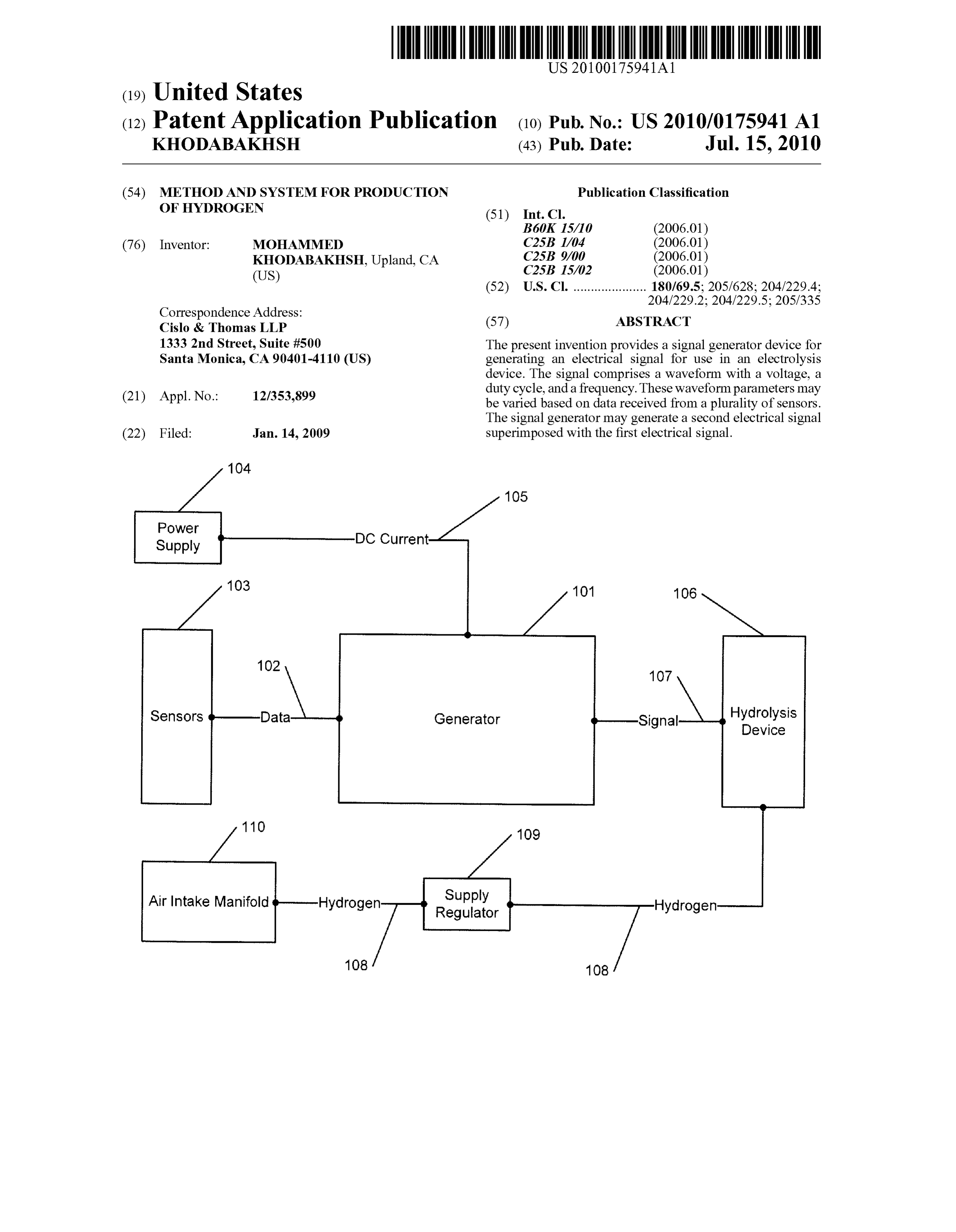
POWer
Supply
Sensors Data Generator Signal Hydrolysis
Air Intake Manifold Hydrogen Supply
Page 2
Drawing sheet — no readable text.
Page 3
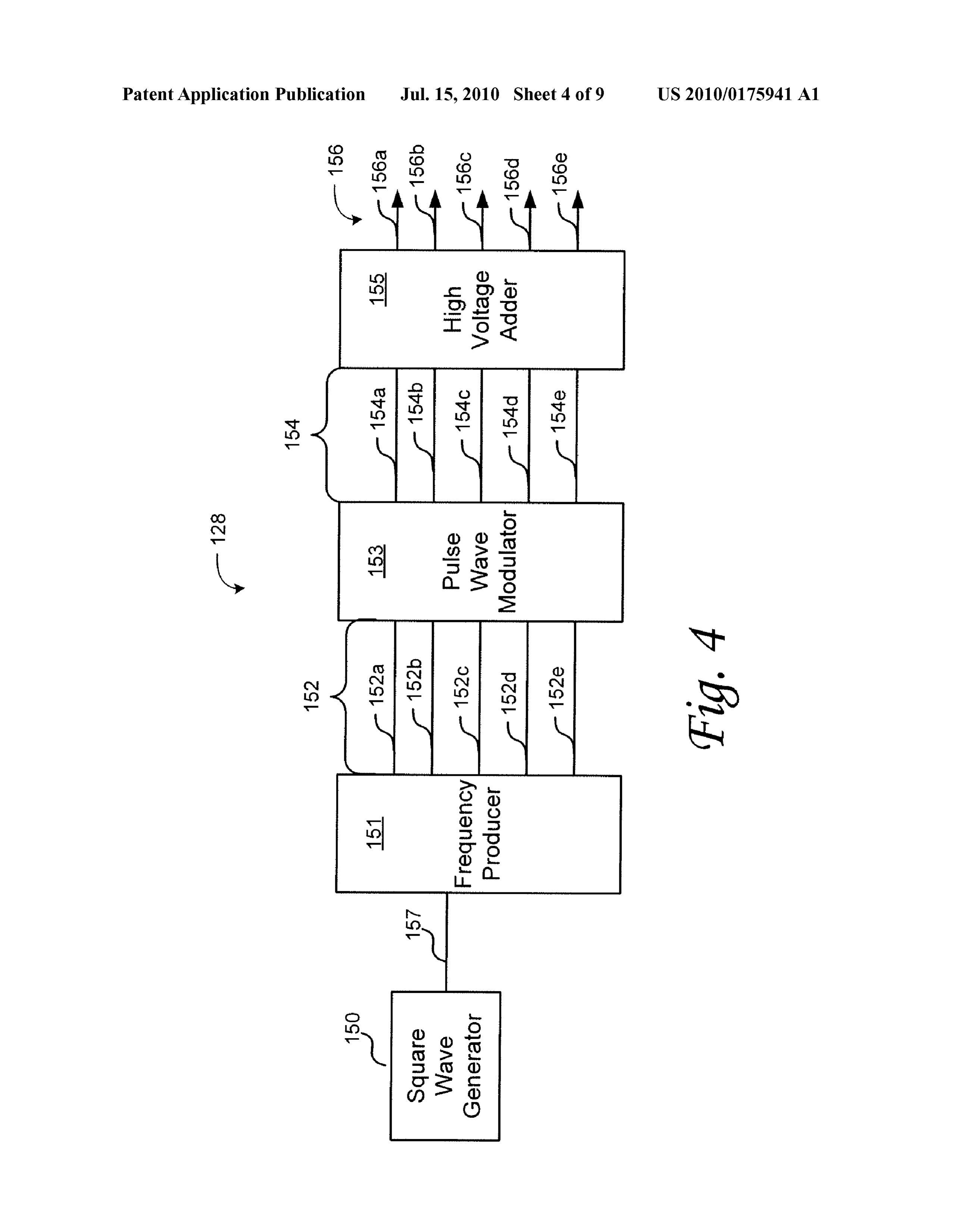
Drawing sheet — no readable text.
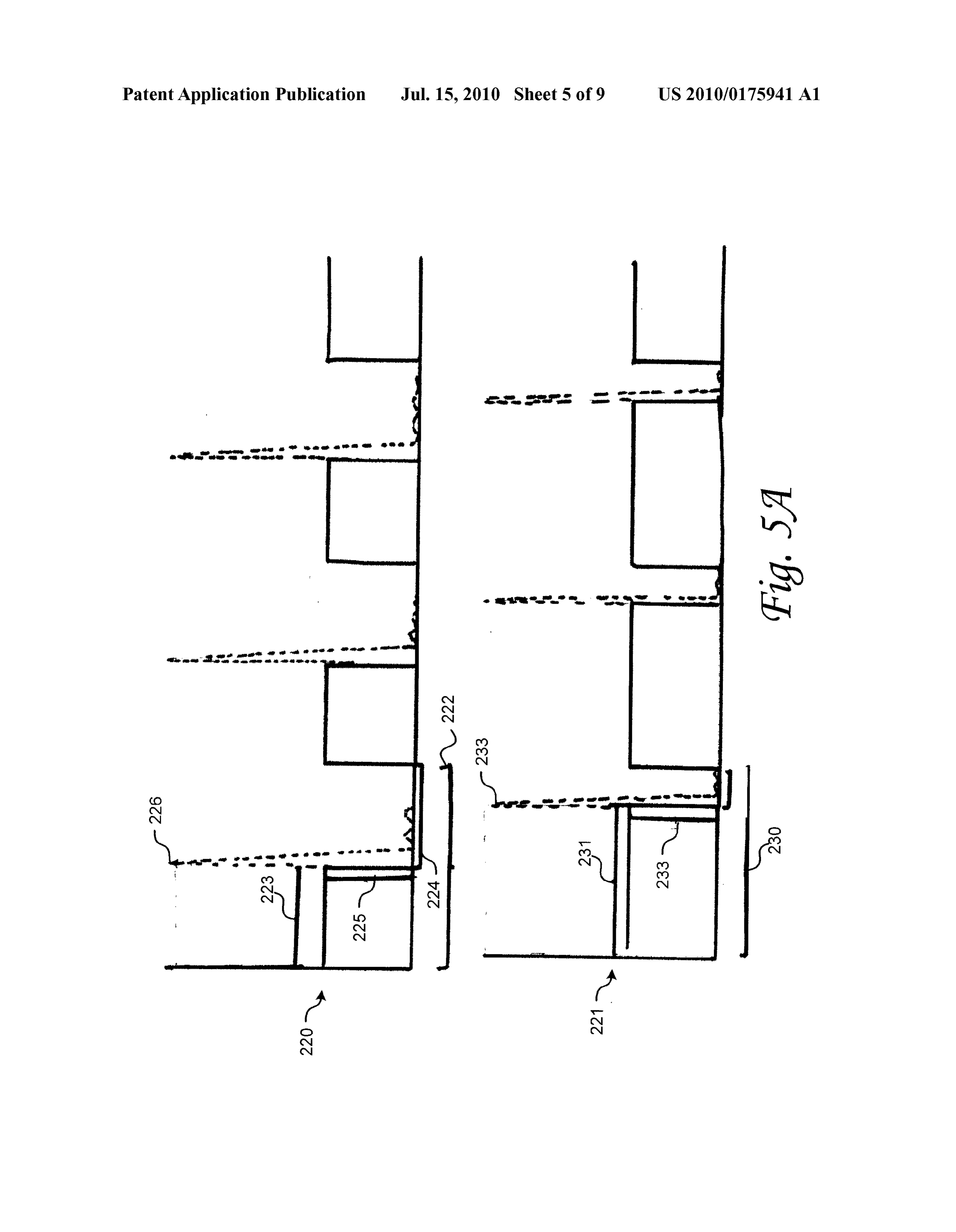
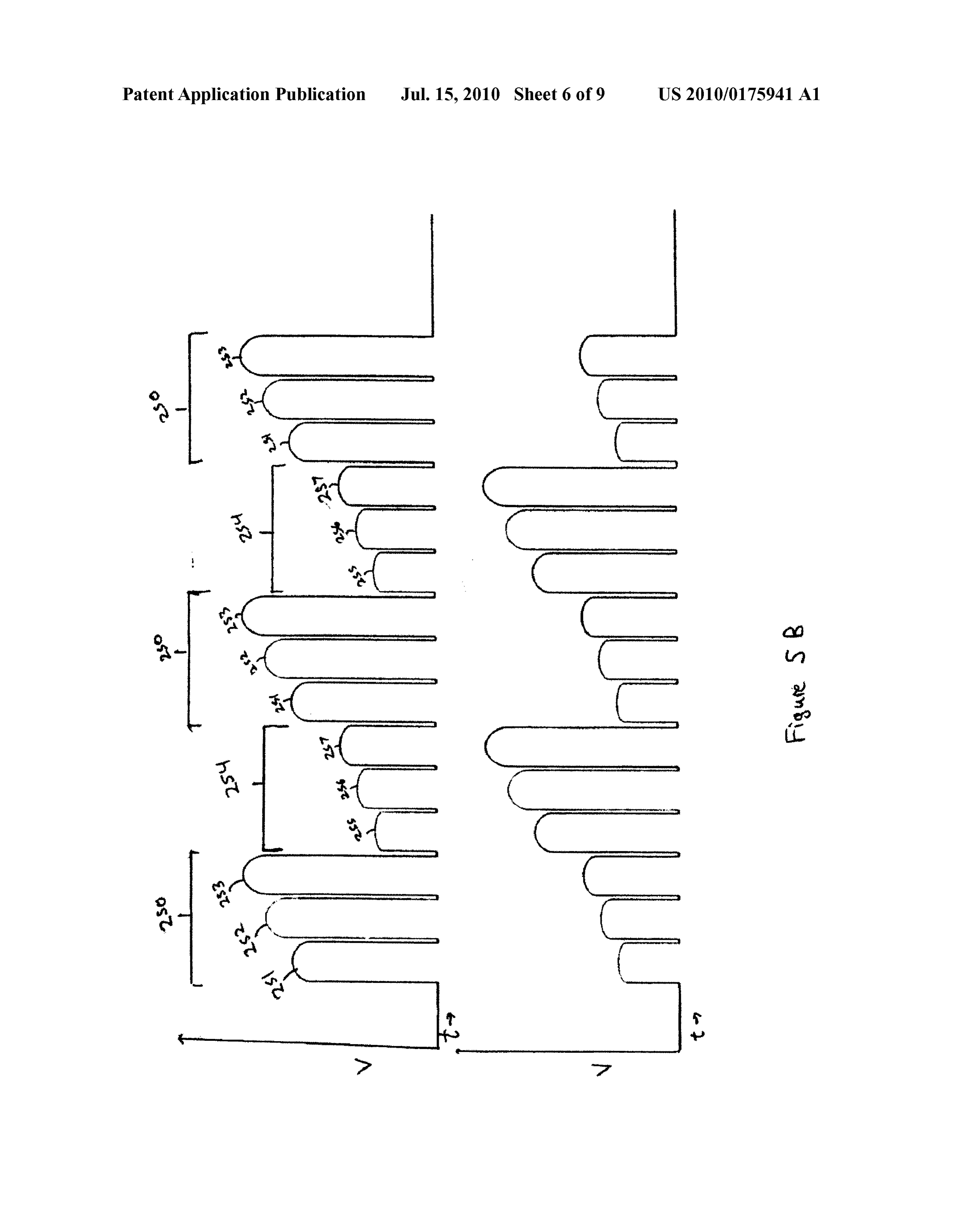
Page 4
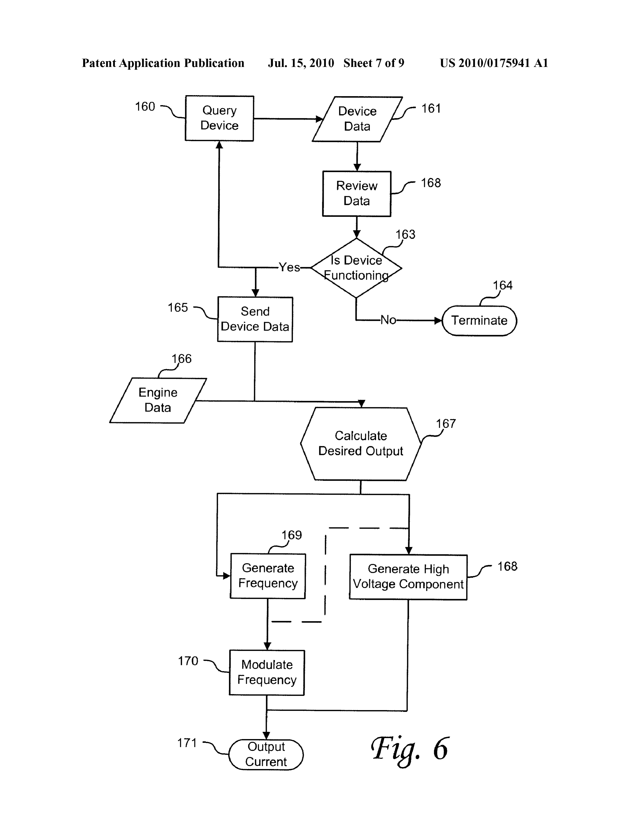
Drawing sheet — no readable text.
Page 5
Drawing sheet — no readable text.
Page 6
Drawing sheet — no readable text.
Page 7
Drawing sheet — no readable text.
Page 8
Drawing sheet — no readable text.
Page 9
Drawing sheet — no readable text.
Page 10
Drawing sheet — no readable text.
Page 11
US 2010/0175941 A1 Jul. 15, 2010
METHOD AND SYSTEM FOR PRODUCTION injection into the vehicle's engine intake. The signal gener OF HYDROGEN ated for use with the electrolysis device, can be a waveform comprising a minimum Voltage, a maximum Voltage, a fre
TECHNICAL FIELD quency, and a duty cycle.
0001. The present invention relates to electronic control 0007 According to a further embodiment of the invention, systems in general, and more particularly, some embodiments the signal is a pulse waveform comprising a rectified pulse relate to electronic control systems for operation of electroly wave with a high Voltage pulse Superimposed at the low sis devices. Voltage portions of the pulse wave. 0008 According to another embodiment of the invention,
DESCRIPTION OF THE RELATED ART a method for providing an electrical signal for an electrolysis device comprises receiving data from a plurality of sensors;
0002 Electrolysis of water to form hydrogen and oxygen and generating an electrical signal based on the data to use in gas is generally known in the art. The gasses produced by this an electrolysis device disposed in a motor vehicle, the signal process may be used for a variety of different purposes. For having a waveform comprising a minimum Voltage, a maxi example, hydrogen may be injected into a car engine's intake mum Voltage, a frequency, and a duty cycle. manifold to increase fuel efficiency and reduce harmful or 0009. According to a further embodiment of the invention, unwanted emissions. the duty cycle of the waveform is varied based at least in part 0003 Hydrogen fuel enhancement by the injection of on data received from the sensors. hydrogen gas into a car engine's intake manifold is well 0010. According to another embodiment of the invention, known to increase fuel efficiency and reduce emissions. a vehicle with a hydrogen gas injection system, comprises: a Hydrogen may be added to a vehicle's air/fuel mixture, generator electrically coupled to an electrolysis device dis thereby allowing the vehicle to run at a leaner air/fuel mixture posed in a vehicle, wherein the generator is configured to than would be possible without the addition of hydrogen. This receive data from a plurality of sensors and to generate the leaner fuel mixture allows the vehicle to perform with better electrical signal from the data, and to generate an electrical fuel efficiency than would otherwise be obtained without the signal for use in the electrolysis device. The signal has a addition of hydrogen gas. waveform comprising a minimum voltage, a maximum Volt 0004 Conventional hydrogen fuel-enhancement systems age, a frequency, and a duty cycle, and provides the electrical use electrical energy generated by the vehicle's alternator to signal to the electrolysis device; and wherein the electrolysis power an electrolysis device. The increased load on the alter device is coupled to an air intake manifold and used to gen nator causes the alternator to place a heavier load on the erate hydrogen gas.
gasoline engine, which negatively affects its fuel efficiency. 0011. Other features and aspects of the invention will In most systems, this reduction in efficiency due to increased become apparent from the following detailed description, generator load outweighs the benefits gained by the addition taken in conjunction with the accompanying drawings, which ofhydrogen. Furthermore, it is well known that as electrolysis illustrate, by way of example, the features inaccordance with takes place the resistive properties of the liquid (i.e. water) embodiments of the invention. The summary is not intended change. Dissolved ions increase the resistivity of the elec to limit the scope of the invention, which is defined solely by trolysis liquid, thus requiring increased energy to perform the the claims attached hereto.
electrolysis, which places an increased load on the alternator.
In current on-board electrolysis devices, this increased BRIEF DESCRIPTION OF THE DRAWINGS requirement further reduces the fuel efficiency gained by the 0012. The present invention, in accordance with one or hydrogen injection system.
more various embodiments, is described in detail with refer
BRIEF SUMMARY OF EMBODIMENTS OF THE ence to the following figures. The drawings are provided for INVENTION purposes of illustration only and merely depict typical or example embodiments of the invention. These drawings are 0005 According to various embodiments of the invention provided to facilitate the reader's understanding of the inven systems and methods are provided that generate a signal used tion and shall not be considered limiting of the breadth, Scope, to power an electrolysis device disposed in a vehicle. The or applicability of the invention. It should be noted that for signal can, in some embodiments, be configured as a pulse clarity and ease of illustration these drawings are not neces wave or a pulse-width-modulated signal to electrolyze the sarily made to scale.
electrolysis liquid. In addition, the signal characteristics Such 0013 Some of the figures included herein illustrate vari as amplitude, duty cycle and frequency, can be adjusted based ous embodiments of the invention from different viewing on a number of factors such as, for example, load on the angles. Although the accompanying descriptive text may engine, resistivity of the water, and so on. Accordingly, the refer to such views as “top,” “bottom’ or “side' views, such signal can be generated based on data received from sensors references are merely descriptive and do not imply or require disposed in a vehicle. The signal can be further configured to that the invention be implemented or used in a particular include a high-voltage pulse at the same frequency to charge spatial orientation unless explicitly stated otherwise. the electrolysis device electrodes for capture of the produced 0014 FIG. 1 depicts an overview of an electrolysis system gasses. and waveform generator in accordance with one embodiment 0006. According to another embodiment of the invention, of the invention.
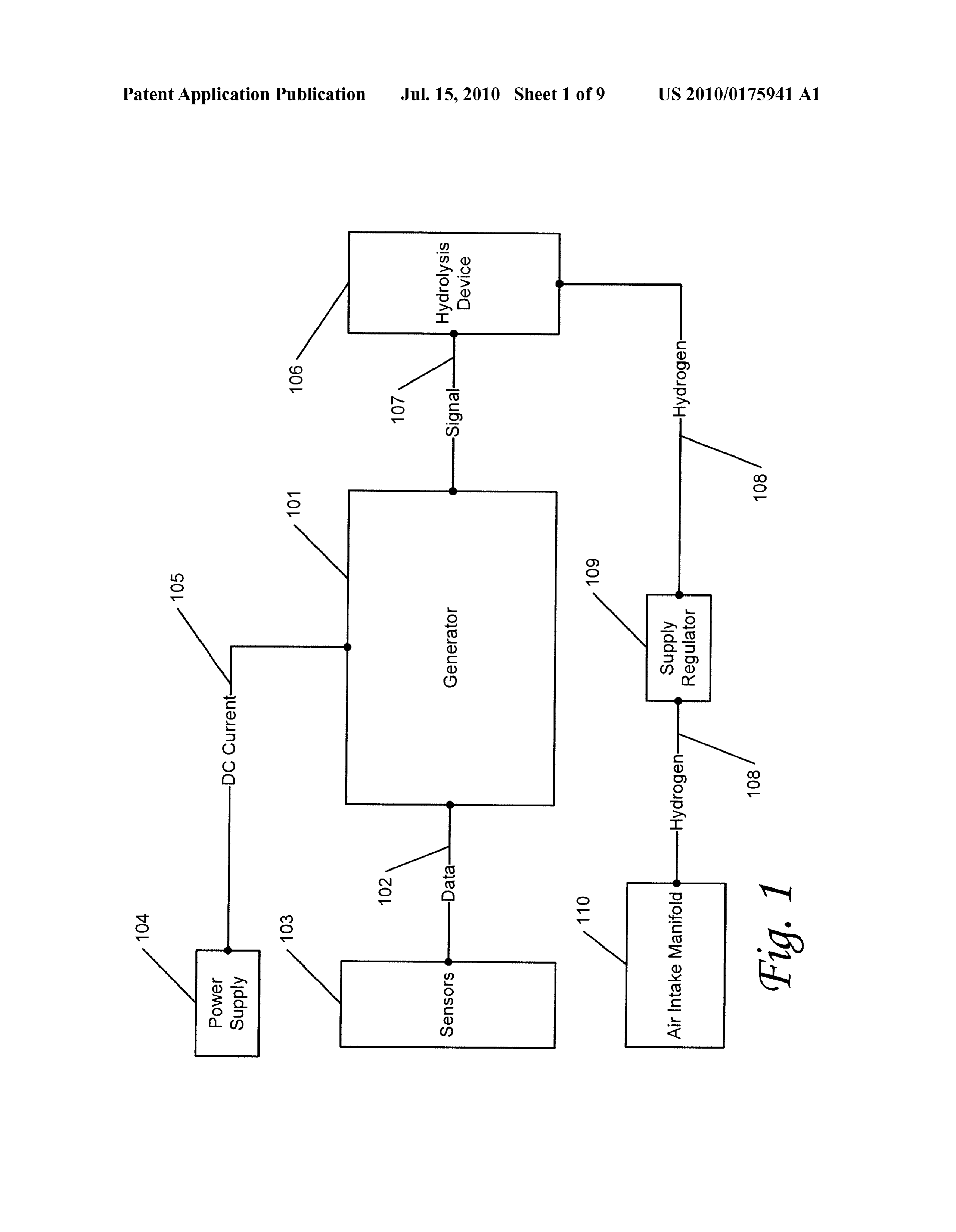
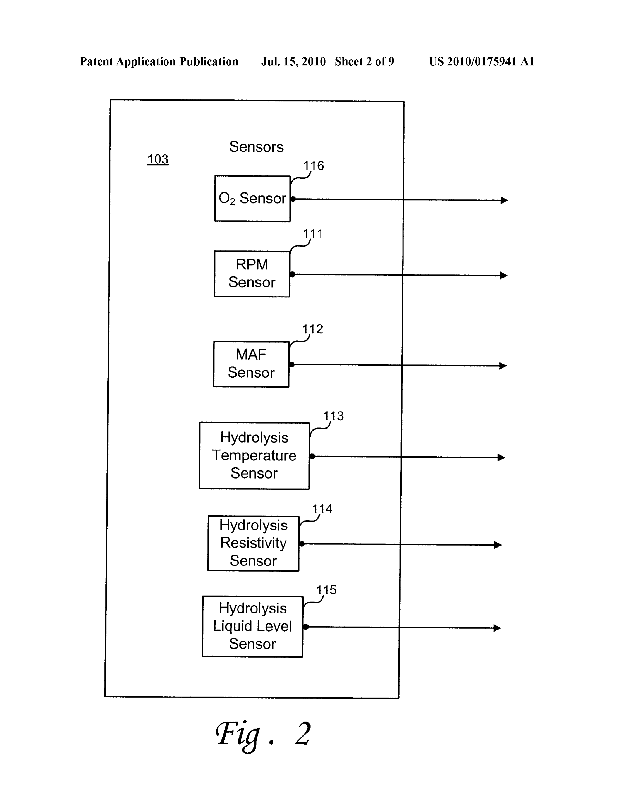
a generator is electrically coupled to an electrolysis device 0015 FIG. 2 depicts an example set of sensors for use in disposed in a vehicle, and is configured to receive data from accordance with one embodiment of the invention. one or more sensors and to generate the electrical signal to 0016 FIG. 3 is a functional block diagram of an example operate the electrolysis device. The generator and electrolysis waveform generator in accordance with one embodiment of device can be disposed in a vehicle to provide hydrogen the invention.
Page 12
US 2010/0175941 A1 Jul. 15, 2010
0017 FIG. 4 is a functional block diagram of an example generator 101 comprises a module that is part of or shared waveform generator in accordance with one embodiment of with another system. For example, in the case of a motor the invention. vehicle, that vehicle's electronic control unit (ECU) or other 0018 FIGS. 5A and 5B depict examples of waveforms computing or control system can be configured to perform the that can be used to operate an electrolysis device in accor functions of waveform generator 101. dance with one embodiment of the invention.
0019 FIG. 6 is an operational flow chart illustrating an 0025. Although a dedicated power supply 104 may be example process for waveform generation in accordance with provided, alternative power sources can be utilized. For one embodiment of the invention. example, the power supply 104 may comprise the vehicle's 0020 FIG. 7 is a functional block diagram of a waveform power Supply. To this effect, in an automobile, motor home, generator with example input and outputs in accordance with semi or other like vehicle, the power supply 104 may com one embodiment of the invention. prise the vehicle's battery or alternator directly, or in other 0021. The figures are not intended to be exhaustive or to embodiments, the power may be drawn from the vehicle's limit the invention to the precise form disclosed. It should be electronic control unit. As another example of a shared power understood that the invention can be practiced with modifi Supply, in a hybrid vehicle, the power Supply 104 may com cation and alteration, and that the invention be limited only by prise the vehicle's battery or electronic control unit. As still a the claims and the equivalents thereof. further example, a special-purpose battery, fuel cell, genera tor, Solar cell, or other power source can be used as the power
DETAILED DESCRIPTION OF THE supply 104 for the system.
EMBODIMENTS OF THE INVENTION 0026. In various examples, the electrolysis device may be 0022. Embodiments of the present invention are directed of the type disclosed in U.S. patent application Ser. No. toward systems and methods for providing generation of 12/271,730, or any other type of electrolysis device. In vari hydrogen through electrolysis. In one embodiment the sys ous examples, the waveform 107 is a pulse wave signal that tem includes a waveform generator that produces a waveform can comprise, for example, a pulse-width modulated signal. having predetermined frequency, amplitude or duty-cycle In some of these examples, waveform 107 may comprise a characteristics to power an electrolysis appartus. The wave waveform of relatively high Voltage Superimposed on the form can be, for example, a pulse-width modulated waveform pulse wave signal. For example, in one embodiment the pulse and can further include a high-frequency component Super wave signal has pulses of relatively low Voltage Swings (for imposed thereon. The hydgrogen generation System, includ example, 0-5 volts, +5 Volts, etc.) between low and high ing the waveform generator and electrolysis apparatus can be states, and the high-voltage waveform has much higher Volt configured to operate so as to provide hydrogen atoms for a age levels Superimposed thereon. In one embodiment, the variety of applications, including for injection into an air high Voltage signal is Superimposed such that it occurs at the intake system of a motor vehicle. low States of the pulse wave signal. In various other examples, 0023. Before describing the invention in detail, it is useful the waveform 107 may comprise a DC current with a voltage to describe a few example environments with which the of at least sufficient potential to enable the electrolysis of invention can be implemented. One Such example is that of a water into hydrogen gas and oxygen gas. gasoline- or diesel-powered vehicle that incorporates the 0027. Although only one electrolysis device 106 is illus waveform generator and the accompanying electrolysis trated, it may be configured to include a plurality of electroly device to produce hydrogen atoms for injection into he vehi sis cells. Likewise, in further examples, the system may Sup cle's air intake. From time-to-time, the present invention is ply waveform 107 to a plurality of electrolysis devices 106. In described herein in terms of these example environments. these examples, the system may supply the same waveform Description in terms of these environments is provided to 107 to each of the plurality of cells or devices 106 according allow the various features and embodiments of the invention to the needs of the engine. Alternatively, in other examples, to be portrayed in the context of an exemplary application. the system may apply different waveforms 107 to various After reading this description, it will become apparent to one members of the plurality. For example, the system may apply of ordinary skill in the art how the invention can be imple a predetermined waveform to a first set of one or more elec mented in different and alternative environments. trolysis devices and may supply the same or a different wave 0024. Referring now to FIG. 1, the illustrated example form to a second set of one or more electrolysis devices, and embodiment includes a power Supply 104, a waveform gen so on, as more hydrogen is needed. erator 101, an electrolysis device 106, a supply regulator 109, 0028. In alternative examples, the supply regulator 109 an air intake manifold 110, and a plurality of sensors 103. supplies hydrogen 108 generated by the electrolysis device According to this example of the invention, generator 101 is 106 to the vehicle's air intake manifold 110. For example, the provided to generate a waveform 107 that is used to operate supply regulator 109 can act as a buffer to store excess hydro the electrolysis device 106. In this example, waveform 107 is gen for injection into the air intake manifold 110 as needed. In generated based on data from the plurality of sensors 103. The Some examples, the Supply regulator is electrically coupled to generator is powered by power supply 104. Waveform 107 and controlled by the generator 101. In other examples, the provides a Voltage potential across an anode and cathode of Supply regulator is self controlled and electrically coupled to the hydrolysis device 106, thereby resulting in the generation the sensor System. In these examples, the regulator is config of hydrogen and oxygen atoms. In the illustrated example, ured to calculate the needed amount of hydrogen from data hydrogen 108 generated in the electrolysis device 106 is provided by the sensors. In other examples, the Supply regu regulated by the supply regulator 109 and provided to the lator comprises a portion of the car's electronic control sys vehicle's air intake manifold 110. In one embodiment, wave tem, and the electronic control system generally calculates form generator 101 is a special-purpose module utilized to the amount of hydrogen injected into the air intake manifold. generate waveform 107. In other embodiments, waveform In other examples, the Supply regulated is omitted entirely
Page 13
US 2010/0175941 A1 Jul. 15, 2010
and all hydrogen produced by the electrolysis device is Sup Such as square wave generator 150 provides a square wave plied immediately to the air intake manifold. signal 157 to a second signal generator Such as frequency 0029 Referring now to FIG.2, an example of a plurality of producer 151. Square wave generator 150 may be any square sensors used to provide data to the generator is shown. For waveform generator as known in the art. For example, square example, sensors 103 may comprise sensors that provide data wave generator 150 may comprise a comparator electrically on the operating state of the engine. Such as: (a) an automo coupled to a capacitor and various resistors as known in the art bile's oxygen sensor (O sensor) 116, (b) an rpm sensor 111. for generating a square wave. In some examples, square wave and (c) a mass airflow (MAF) sensor 112. In various generator is configured to output a square wave 157 that examples, the generator 101 receives the data from the sen varies between a maximum Voltage and a minimum Voltage. sors 103 themselves directly. In alternative examples, this To avoid the generation of oxygen at the hydrogen electrode sensor data may be supplied by the vehicle's electronic con of the electrolysis device, in these examples the minimum trol unit (not shown) to the waveform generator 101. Sensors Voltage has the same sign as the maximum Voltage. For 103 may also include sensors that provide data on the oper example, in some examples, the square wave varies between ating state of the electrolysis device. Such sensor may a +12V maximum Voltage and OV minimum Voltage. In other include, for example: (a) a temperature sensor 113, (b) a examples, a square wave that varies symmetrically between a resistivity sensor 114, and (c) a liquid level sensor 115. As maximum and minimum Voltage that has the same absolute these examples serve to illustrate, additional or other sensors value, for example between +12V and -12 V. In these may be used in conjunction with the system to provide data examples, the waveform may be modified later for proper that can be used by waveform generator 101 to generate conformation with the requirements for an electrolysis appropriate waveforms 107 or to regulate supply of hydrogen device. For example, the square wave may be passed through 108 to air intake manifold 110. a rectifier as known in the art to provide a waveform that 0030 Referring now to FIG. 3, an example implementa varies between 0 V and +12 V.
tion of a waveform generator 101 is described. In this 0034 Referring still to FIG. 4, a second signal generator example, generator 101 might include, for example, one or Such as frequency producer 151 provides a frequency-ad more processors, controllers, control modules, or other pro justed square wave 152 to pulse wave modulator 153. Fre cessing devices, such as a processor 127. Processor 127 might quency producer 151 may be electrically coupled to the pro be implemented using a general-purpose or special-purpose cessor or processing module and configured to provide a processing engine Such as, for example, a microprocessor, waveform with a frequency configured to enable efficient controller, or other control logic. Generator 101 may further generation of hydrogen in an electrolysis device. Frequency comprise a signal producing module 128 and a memory mod producer 151 may comprise a frequency divider to provide a ule 129. The processor computes a desired waveform for the frequency adjusted square wave 152 with a frequency which signal 107 based on data 102 provided by the sensor system is a rational number multiple of the initial square wave 157. (not shown). The desired signal 107 is generated by the signal Frequency producer 151 may be any module which adjusts producing module 128. In various examples, the processor the frequency of an input signal in order to Supply an output computes the desired waveform in real time based on incom signal with an adjusted frequency. For example, the fre ing data from the sensors. quency producer could be implemented using an analog fre 0031. In alternative examples, the generator module 101 quency divider Such as a regenerative frequency divider oran further comprises a memory 129. For example, preferably injection-locked frequency divider, a digital signal divider, or random access memory (RAM) or other dynamic memory, a fractional-n divider.
might be used for storing information and instructions to be 0035. In the illustrated example, frequency producer 151 executed by processor 127. Memory 129 might also be used includes a plurality of signal generators such as dividers to for storing temporary variables or other intermediate infor provide a plurality of output signals 152a-e at a plurality of mation during execution of instructions to be executed by different frequencies. In these examples, the generator 128 processor 127. Generator 101 might likewise include a read may select from the plurality of discrete frequencies depend only memory (“ROM) or other static storage device for ing on the hydrogen needs of the engine. In further examples, storing static information and instructions for processor 127. frequency generator 151 may be configured to output a wave In these examples, the processor module may be configured form 152 which may vary continuously in frequency. In this to generate a waveform based on current data coming from example, the generator may select the preferred frequency to the sensor System and on past data previously provided by the be generated based on the hydrogen needs of the engine. system. In other examples, the generator is configured to Those of ordinary skill in the art will appreciate other meth provide a particular waveform without regard to data, such a ods for generating frequencies for use in an electrolysis waveform being calculated to provide hydrogen operation in device without departing from the scope of the present inven all engine operative modes. tion.
0032. In particular examples, the processor module 127 0036 Referring still to FIG. 4, in some examples, a pulse provides the desired waveform to the signal producing mod wave modulator 153 that is electrically coupled to the pro ule 128. The signal producing module 128 then forms the cessor is configured to modulate the duty cycle of the wave waveform for the signal. Those of ordinary skill in the art will form 152 in accordance with the needs of the engine. For appreciate various equivalent architectures or configurations example, if increased hydrogen output is required, pulse wave that form a desired signal based on incoming data without modulator may increase the duty cycle so that power is being departing from the scope of the invention. provided to the electrolysis device over a longer period in 0033 Referring now to FIG.4, an example embodiment of each wavelength. Pulse wave modulator may comprise any a signal producing module 128, as described above, may be analog or digital system or architecture known in the art for used to create a plurality of waveforms 156 for use in an varying the duty cycle of an electrical signal or waveform. In electrolysis device. In this example, a first signal generator Some examples, the frequency producer 151 outputs a single
Page 14
US 2010/0175941 A1 Jul. 15, 2010
square wave waveform that varies in frequency. In these trated by dashed waveform 226, output waveform 220 may examples, the pulse wave modulator outputs a single pulse further comprise a high Voltage waveform with a peak Voltage wave waveform 154 in accordance with the power needs of of V, Superimposed on the lower Voltage pulse waveform. the electrolysis device. In examples comprising a plurality of Output waveform 220 is configured and generated by the frequency adjusted waveforms 152a-e, pulse wave modulator generator to produce hydrogen gas in an electrolysis device. 154 may be configured to output a plurality of pulse wave 0041. In the illustrated example, an output signal 220 com waveforms 154a-e corresponding to the number of frequency prises a 12-volt peak-to-peak square wave with +12V maxi adjusted waveforms 152a-e. In these examples, pulse wave mum voltage and OV minimum voltage with a 50% duty modulator 153 may comprise a plurality of separate pulse cycle. The periodicity 222 may correspond to a desired fre adjusting modules, or may comprise a single system that is quency, which in one embodiment is approximately 43,430 able to act on each frequency adjusted waveform. HZ. This frequency can be chosen and adjusted to improve 0037 Referring still to FIG. 4, in some examples, a high the efficiency of the production of hydrogen. In some voltage adder 155 is configured to output a final waveform examples, a plurality of secondary wavelengths correspond 156 with a high voltage waveform superimposed onto the ing to Subharmonics of the first wavelength may also be pulse wave 154. In these examples, high voltage adder 155 is provided. For example, a primary wavelength at 43,430 Hz, a configured to Superimpose a high Voltage waveform onto the first harmonic of 21,715 Hz, a second harmonic of 14,476.67 minimum voltage portion of the pulse wave 154. High voltage HZ, a third harmonic of 15,517.5 Hz and a fourth harmonic of adder 155 may comprise any analog or digital circuit config 8,686 Hz may be provided. In these examples, the inclusion of ured to output a high Voltage waveform. In a further example, the Sub harmonics may be optional, for example, the fourth high voltage adder 155 may be configured to superimpose the harmonic may sometimes be omitted. In other examples, a derivative of the pulse waveform on the pulse waveform. In frequency in the range of 42 kHZ-45.8 kHz is chosen. In this example, the high Voltage adder may comprise opera further examples, a wavelength with a frequency of 143,762 tional amplifiers, capacitors, and resistors electrically HZ may be chosen. In these examples, Sub harmonics may coupled into a derivator circuit configuration as known in the also be included, for example: a first harmonic of 71.881 Hz, art a second harmonic of 47,920.67 Hz, a third harmonic of 0038 Referring now to FIG. 5A, a few exemplary output 35,840.1 Hz, and a fourth harmonic of 28,752.4 HZ. Or, in waveforms 220 and 221 are now described. As discussed other examples, a frequency in the range of 110 kHz to 180 above, the output waveform is applied across two electrodes kHz may be chosen.
of an electrolysis device to break the hydrolysis fluid into its 0042. In the illustrated example, high voltage waveform constituent components. In the case of breaking water into 226 comprises a waveform with a brief peak at a high Voltage hydrogen and oxygen, hydrogen gas forms at the positively V. The high voltage waveform may serve multiple uses in the charged cathode and oxygen gas forms at the negatively electrolysis device. For example, high voltage waveform 226 charged anode. In order to ensure that the desired gas is may provide a briefburst of voltage that serves to cleanse the produced at the proper electrode, the polarity of the signal electrolysis device's electrodes of built up ions, which should not be reversed. For example, the terminal designated increase the resistance of the electrolysis liquid. Or for as the cathode should not be negatively charged during opera example, high Voltage waveform 226 may serve to degas the tion. Therefore, it is preferable that the minimum and maxi electrolysis fluid by cleansing the electrodes of aqueous dis mum Voltage of the output signal maintain the same sign. In Solved hydrogen and oxygen molecules. In particular examples, where a mixture of hydrogen gas and oxygen gas, examples, waveform 226 may comprise a 1,500 V brief DC or Brown's gas, is acceptable or desired, the maximum and pulse that corresponds to a derivative of the voltage drop of minimum Voltages may be of different signs. the square wave portion of output signal 220. In other 0039 FIG. 5A presents two plots of final output signals examples, high Voltage waveform 226 may comprise an AC 220 and 221 on a graph with voltage and time axes. The pulse with a peak-to-peak voltage of 1,500 V. In various Voltage scale depicted in this example is not a linear scale, and examples, the AC pulse may alternate current at a ultrahigh is illustrative of the described principles only. Although the frequency of 2.9 GHz, 3.8 GHz, or 4.7 GHz. In further waveforms 220 and 221 are shown to be substantially ideal examples, a second alternating current at a very high fre (for example, sharp transitions, no ringing), non-ideal wave quency of 380 MHz, 470 MHz, or 650 MHz may be super forms may be used. Although waveforms that correspond to at imposed with the ultrahigh frequency through any method least the first twelve harmonics of the Fourier transform of an known in the art. Those of ordinary skill in the art will appre ideal square or pulse wave may preferably be used, more or ciate other potential waveform characteristics and other less than twelve harmonics may be used in approximating an methods for forming a high Voltage waveform without ideal square or pulse wave. Alternatively, other waveforms, departing from the scope of present invention. Such as a triangular or sinusoidal waveform or other wave 0043 Referring still to FIG. 5A, output signal 221 illus form may be used. trates another example output signal for use in an electrolysis 0040. Referring still to FIG.5A, in various examples, out device. This example illustrates the use of a varied duty cycle. put waveform 220 comprises a square wave with a periodicity In the illustrated examples, wavelength 230 is substantially 222. Output waveform 220 can be further characterized by a the same as wavelength 222, and thus output waveform 221 duty cycle, which is the ratio of the active pulse length 223 has substantially the same frequency as output waveform 220. and the inactive pulse length 224. In the illustrated example, However, active pulse length 231 is longer than active pulse output waveform 220 has an approximately 50% duty cycle length 223 and inactive pulse length 232 is less than inactive because the active pulse length 223 is approximately 50% of pulse length 224, corresponding to a greater duty cycle. In the the total wavelength 222. Output waveform 220 further com illustrated example, the duty cycle of output waveform 221 is prises a Voltage Swing 225 between low and high states, approximately 75%. Therefore, output waveform 221 con which in this example is approximately 12 volts. As illus tains 50% more power than output waveform 223. All other
Page 15
US 2010/0175941 A1 Jul. 15, 2010
factors being equal, hydrogen gas production in an electroly this may indicate a fault in the device or circuit requiring sis device will typically increase with increased duty cycle termination. Or if the resistivity or temperature exceed a under normal operating conditions. Thus, by varying the duty predetermined operating bound, the device may require ter cycle, the hydrogen production may be adjusted without mination.
varying the Voltage or frequency. This may be beneficial 0047. At decision step 163, it is determined whether the when the Voltage and frequency are chosen for most efficient device is functioning. If the review and analysis step 162 production of hydrogen. indicates that the device is not functioning properly, then the 0044) Referring now to FIG. 5B, this example illustrates device terminates as indicated in block 164. If the device is an alternative electrical output 249. The example output 249 determined to be functioning properly, then at step 165 the may comprise a series of pulses, with a pulse width 258 and an device data is sent to a processor for waveform calculation. inactive width 259. In some examples, the pulse group 250 Additionally, if the device is functioning, then query step 160 comprises high Voltage pulses directed to collection elec may be repeated for iterative examination of device function trodes disposed within an electrolysis device. In these ality.
examples, the pulse group 254 is directed to formation elec 0048. At step 166, a desired output is calculated. In this trodes disposed within an electrolysis device. In further example, the output waveform can be determined at least in examples, the electrolysis device does not have separate col part from engine data 166 and device data provided in step lection and formation electrodes. In which case, the pulse 165. Engine data 166 may comprise, for example, data from: groups 250 and 254 are directed to the same electrodes. In the (1) the engine's O sensor, (2) the RPM sensor; and (3) the example illustrated in FIG. 5, pulse group 254 comprises MAF or MAB sensor. Device data 161 and engine data 166 three separate pulses 255, 256, and 257 of approximately can be sampled and updated periodically to allow dynamic equal pulse width. These pulses 254 and 250 may each be ongoing adjustment of the output waveform. modeled as three separate pulse train waveforms with Small 0049. In various examples, calculation step 167 may com duty cycles Superimposed upon each other at a phase differ prise reviewing the device data 161 and engine data 166 to ence of approximately one pulse width. In some examples, determine desired output waveforms. For example, if the the duty cycle of each pulse in the pulse group may be inde engine is placed under an increased load, Such as during pendently modified. In other examples, the duty cycle of the acceleration, then the calculation may call for an increased entire pulse group may be modified. In particular examples, amount of hydrogen. In this case, the amount of power pro the duty cycle may vary between 10% and 90%. In various vided to the electrolysis device may be increased. As noted examples, the pulse groups 250 may serve as high Voltage above, this can be increased by, for example, increasing the pulses that charge electrodes in an electrolysis device for output waveform duty cycle or by increasing Voltage. In other collecting hydrogen and oxygen ions formed during elec examples, the engine data may indicate that the engine is trolysis. In these examples, the pulse groups 254 may serve to under a light load, such as during cruising under constant Supply the energy needed for the electrolysis reaction. Velocity or coasting to a stop. Therefore, the calculation may 0045. In particular examples, the pulses 251,252, and 253 indicate that less hydrogen is needed in the mixture. In this may each have the same Voltage, for example a Voltage of case, the amount of power provided to the electrolysis device between 450 V and 10,000 V. In other examples, some or all may be decreased by lessening the output waveforms duty of the pulses may each have a different Voltage, for example cycle or Voltage.
pulse 251 at 450 V, pulse 252 at 550 V, and pulse 253 at 650 0050. In further examples, a high voltage waveform is V. In further examples, the pulses 255,256, and 257 may each determined and included to facilitate the production of hydro have the same Voltage, for example a Voltage between 6V and gen in the electrolysis device. For example, the data from the 12 V. In other examples, the pulses 255, 256, and 257 may device may indicate that the resistivity of the device is each have a different voltage, for example pulse 255 at 6 V. increasing, thus lowering the efficiency of the device. In this pulse 256 at 10 V, and pulse 257 at 12 V. In some further example, a high Voltage waveform may be provided to charge examples, a second output Substantially similar to output 249 the electrolysis device's electrodes briefly in such a way to but at a lower frequency, for example: 3,000 Hz may be eliminate excess dissolved ions in the electrolysis liquid, thus introduced to the electrolysis device. This second output may increasing the device efficiency. In alternative examples, mul be introduced at a second set of electrodes in the electrolysis tiple desired waveforms may be calculated and applied. For device, or may be Superimposed with the first output and example, an ultrahigh frequency (UHF) waveform and a very introduced at a single set of electrodes. In alternate examples, high frequency (VHF) waveform may be determined and multiple further outputs may be introduced in a similar man applied in a combined manner. In some examples, these mul . tiple waveforms may then be provided at separate outputs and 0046 Referring now to FIG. 6, an exemplary flow chart of superimposed for use in the electrolysis device. In other a system and method for efficient generation of hydrogen is examples, these multiple waveforms may be provided at presented. At step 160, the electrolysis device is queried for separate outputs and utilized to operate different cells at a data and the data provided at step 161. Device data may multi-cell electrolysis device at different operating wave comprise, for example, data concerning: (1) fluid levels, (2) forms.
resistivity of the electrolysis liquid, and (3) temperature of the 0051. At step 169 a frequency portion of the calculated electrolysis liquid. At step 162 the device data is reviewed and waveform is formed. In alternative examples where multiple analyzed. The review and analysis may comprise analyzing desired waveform are calculated, step 169 may comprise the liquid levels to make determine whether or not there is forming one or more frequency portions of the multiple sufficient reserve liquid to continue operation of the electroly desired waveforms. Step 168 may comprise forming the high sis device. Or, in other examples, the review and analysis may Voltage component calculated in step 167. In some examples, comprise analyzing the resistivity or temperature sensor data. the high Voltage component may be formed separately from For example, if the resistivity is determined to rapidly change, the frequency component. In other examples, the frequency
Page 16
US 2010/0175941 A1 Jul. 15, 2010
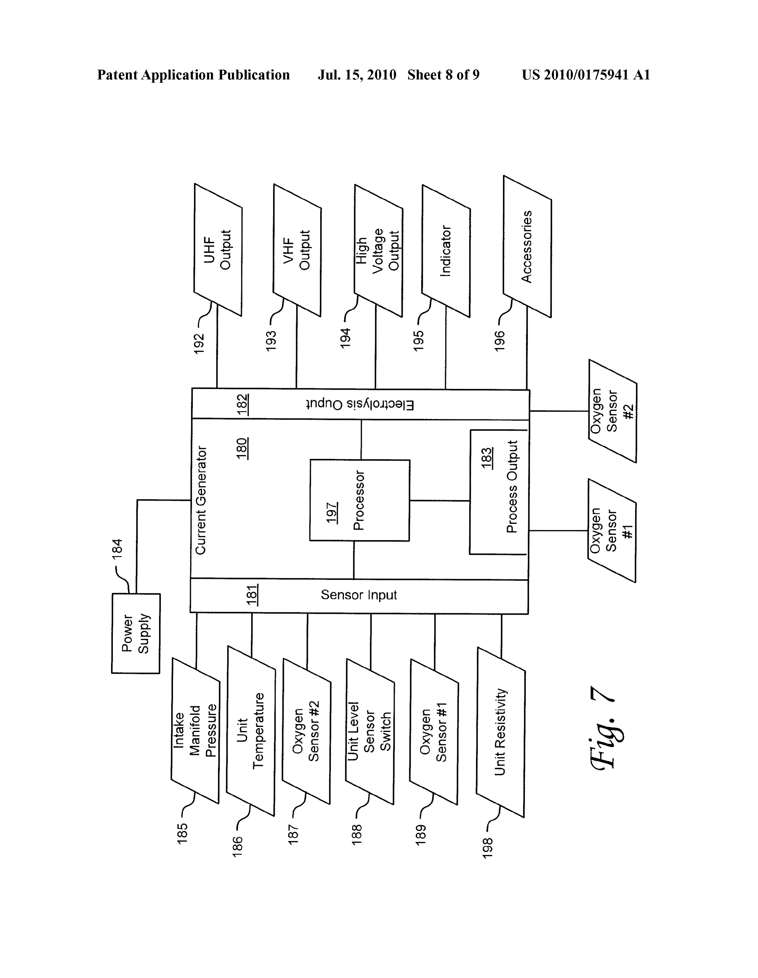
component may be utilized in the formation of the high volt physical properties of the electrolysis liquid have changed, age component, such as through the use of a differentiator op Such as through increased temperature or higher ion dissolu amp circuit, for example. At step 170 the duty cycle of the tion, the processor may vary the frequency or high Voltage output waveform is modulated according to the need calcu pulse amplitude of the provided waveform. In some lated in step 167. At step 171 the formed output waveform is examples, the processing module may terminate operation of provided to the electrolysis device. In those examples com the device if until level sensor switch 188 indicates that the prising multiple desired output waveform, these output wave electrolysis liquid levels are too low. Or, in other examples, form are provided at step 171. the unit level sensor switch 188 may be configured to auto 0052 FIG. 7 illustrates a functional block diagram of an matically terminate the device operation itself, if liquid levels example waveform generator in accordance with one are too low.
embodiment of the invention. Referring now to FIG. 7, wave 0054 Referring still to FIG. 7, some examples may form generating module 180 might include, for example, one include a process output module 183. In examples where the or more processors, controllers, control modules, or other invention is not integrated with a vehicle ECU, it may be processing devices, such as a processor 197. Processor 197 helpful to adjust the data that the oxygen sensors 190 and 191 might be implemented using a general-purpose or special provide to the vehicle's ECU. For example, once hydrogen is purpose processing engine Such as, for example, a micropro cessor, controller, or other control logic. Processor 197 may injected into the air/fuel mixture, the fuel will burn more be connected to a bus (not shown), although any communi efficiently, thus indicating to the oxygen sensors that the cation medium can be used to facilitate interaction with other vehicle may utilize a leaner air/fuel mixture. This may create components of waveform generating module 180 or to com a feedback loop that results in an air/fuel mixture which is too municate externally. Waveform generating module 180 might lean even with the addition of hydrogen. The processor mod also include a sensor input module 181. Sensor input module ule may avoid this by utilizing process output module 183 to 181 may comprise a portion of a I/O interface as known in the adjust the data provided by oxygen sensors 190 and 191 to the art although any method for communicating external data to ECU.
a computing unit or processor may be used. Waveform gen 0055 Referring still to FIG. 7, the processor may be con erating module 180 might also include a process output mod figured to Supply signals to form the desired waveform ule 183. Process output module 183 may comprise a portion through the electrolysis output module 182. Electrolysis out of a I/O interface as known in the art although any method for put module 182 may be configured to send the signals to communicating to external sources from a computing unit or waveform generators, or may be configured to generate the processor may be used. Waveform generating module 180 desired waveform itself. Electrolysis output module 182 may might also include an electrolysis output 182. Electrolysis comprise a plurality of various outputs. For example, without output 182 may comprise a suitable power source outlet as limitation, such outputs may comprise: (1) a UHF output 192: known in the art or, alternatively, electrolysis output may (2) a VHF output 193; (3) a High Voltage Output 194; (4) an comprise a signal source to enable further modules to provide indicator 195; and (5) various accessories 196. Some a power source. Waveform generator may be powered by examples may include an indicator 195 electrically coupled power supply 184. Power supply 184 may comprise the vehi to a signaling device disposed where visible in the car. For cle's power Supply. For example, in a combustion engine example, the indicator 195 could be an LED or display screen vehicle, the power Supply may comprise the alternator disposed on the vehicle's dashboard. In some examples the directly, or in other embodiments the power may be drawn indicator may signal whether or not the device is operating. In from the vehicle's electronic control unit. In a hybrid vehicle, other examples, the indicator may indicate the operative the power Supply may comprise the vehicle's electric motor parameters of the device. Further examples may include a or electronic control unit. In some examples, the invention variety of accessories 196, as would be appreciated by those may be integrated into a vehicle's electronic control system skilled in the art. For example, a global positioning system (“ECU). In these examples, the processor module may com (GPS) unit accessory could be provided which would allow prise the processor disposed within the ECU and the sensor for greater predictive use of the electrolysis device. input, process output modules, and electrolysis outputs may 0056 Referring still to FIG.7, the UHF output 192 may be utilize a preexisting IO system within the ECU. configured to output a pulse wave that contains a waveform 0053 Referring still to FIG. 7, sensor input module 181 that is configured to efficiently separate gasses in an electroly may be configured to receive data from a plurality of sensors. sis device. For example, in an electrolysis device containing The plurality of sensors may comprise, for example, without water the waveform may comprise a pulse wave at a fre limitation: (1) intake manifold pressure sensor 185; (2) oxy quency of 2.90 GHz, a voltage of 12V, and duty cycle of 50% gen sensor #1189; (3) oxygen sensor #2 187; (4) unit tem Other examples may use different waveform parameters, for perature sensor 186; (5) unit resistivity sensor 198; and (6) example frequency may be any frequency within 2-4 GHZ, unit level sensor switch 188. Sensor input module 181 may be voltage may be within 1.2-50V and the duty cycle may be further configured to provide the received data to processor within 10%-90%. In other examples, the UHF output may be module 197. Sensor data may be used to calculate the desired configured to output a plurality of different waveforms based waveform to be supplied to the electrolysis device. For on apparatus requirements. For example, the processor and example, if data from the intake manifold pressure sensor UHF output may be configured to operate in a three-mode 185, and oxygen sensors 189 and 187 indicate that the engine manner, as follows: Mode 1 may operate at a 2.90 GHz: Mode is under higher load, then the processor may supply a wave 2 may operate at 3.80 GHz; and Mode 3 may operate at 4.7 form which generates more hydrogen than normal. For GHz. In other examples, the frequencies may be within a example, by increasing the Voltage or duty cycle of the pro range for each mode. For example, Mode 1 may be at a range vided waveform. As a further example, if the resistivity sensor of 2-4 GHz, Mode 2 may beat a range of 3-5 GHZ, and Mode 198 and the unit temperature sensor 186 indicate that the 3 may be at a range of 4-6 GHz.
Page 17
US 2010/0175941 A1 Jul. 15, 2010
0057. Other examples may include a VHF output 193. The generated ions do not need to be collected until the off periods VHF output 192 may be configured to output a pulse wave of the waveforms. By configuring the High Voltage Output to that contains a waveform that is configured to efficiently provide a high Voltage waveform only during the off periods separate gasses in an electrolysis device. For example, in an this collection may be achieved at lower energy use. Further electrolysis device containing water the waveform may com more, in these examples, the High Voltage Output also has an prise a pulse wave at a frequency of 380 MHz, a voltage of off period. During this off period ions which have accumu 12V, and duty cycle of 50%. The VHF output may also be lated but not formed into hydrogen or oxygen gas are allowed configured to operate in a multi-mode configuration. For to disperse. This dispersion prevents the resistivity of the example, mode 1 may operate at 380 MHz, mode 2 may electrolysis from increasing to an inefficient level. In other operate at 470 MHz, and mode 3 may operate at 650 MHz. In examples, the High Voltage Output may be further configured these multi-mode configurations, the UHF and VHF outputs to provide a brief burst of opposite voltage to the electrodes. may operate in the same mode at the same time, or may This burst may enable a more rapid dispersion of resistivity operate in different modes simultaneously. For example, the increasing ions.
UHF and VHF outputs may be configured so that both operate 0062. As used herein, the term module might describe a in mode 1 at the same time, or they may be configured so that given unit of functionality that can be performed in accor one is operating in mode 1 while the other is operating in dance with one or more embodiments of the present inven mode 2. tion. As used herein, a module might be implemented utiliz 0058 Other examples may use different waveform param ing any form of hardware, Software, or a combination thereof. eters, for example the VHF frequency output may be any For example, one or more processors, controllers, ASICs, frequency within 300-450 MHz, the voltage may be within PLAS, logical components, Software routines or other mecha 1.2-50V and the duty cycle may be within 10%-90%. The nisms might be implemented to make up a module. In imple VHF output wave and the UHF output wave may be super mentation, the various modules described herein might be imposed, for example, without limitation, additively or mul implemented as discrete modules or the functions and fea tiplicatively, to obtain an Superimposed wave that breaks tures described can be shared in part or in total among one or down an electrolysis fluid with increased efficiency. more modules. In other words, as would be apparent to one of 0059. Further examples may include a High Voltage Out ordinary skill in the art after reading this description, the put 194. In some examples, the High Voltage Output 194 is various features and functionality described herein may be configured to Supply a charge to electrodes in an electrolysis implemented in any given application and can be imple device. This charge allows the hydrogen ions and oxygen ions mented in one or more separate or shared modules in various broken apart by the UHF and VHF waveforms to be collected combinations and permutations. Even though various fea at separate electrodes for formation into and separate collec tures or elements of functionality may be individually tion of hydrogen and oxygen gas. In some examples, High described or claimed as separate modules, one of ordinary Voltage Output 194 provides a DC current of 1500V. In other skill in the art will understand that these features and func examples, High Voltage Output 194 may provide a DC cur tionality can be shared among one or more common Software rent in the range of 200-2000V. and hardware elements, and Such description shall not require 0060. In other examples, High Voltage Output 194 may be or imply that separate hardware or software components are configured to Supply a high Voltage waveform which also used to implement Such features or functionality. varies with time. In particular examples, the high Voltage 0063. Where components or modules of the invention are waveform may vary at a frequency of 43430 Hz or 143762 implemented in whole or in part using software, in one HZ. The high voltage waveform may be 1500V peak to peak embodiment, these software elements can be implemented to and may comprise a DC offset. For example, the high Voltage operate with a computing or processing module capable of waveform may have a 1500V peak to peak waveform with a carrying out the functionality described with respect thereto. 500V DC offset. In certain examples, the High Voltage Out After reading this description, it will become apparent to a put may be configured to one or the other of these frequencies. person skilled in the relevant art how to implement the inven In other examples, the High Voltage Output may be config tion using other computing modules or architectures. ured to output both of these frequencies in a Superimposed 0064. Where components or modules of the invention are wave. In further example, the High Voltage Output may be implemented in whole or in part using software, in one further configured to Superimpose Sub harmonic frequencies embodiment, these software elements can be implemented to onto the high voltage waveform. For example, the High Volt operate with a computing or processing module capable of age Output might output a waveformat a 43430 Hz frequency carrying out the functionality described with respect thereto. superimposed with: a 21715 Hz frequency, a 14476.67 Hz One Such example-computing module is shown in FIG. 8. frequency, a 15517.5 Hz frequency, and a 8686 Hz frequency. Various embodiments are described in terms of this example Or, if the waveform is output at 143762 Hz, sub-harmonics of computing module 300. After reading this description, it will 71881 Hz, 47920.67 Hz, 35840.1 Hz, and 28752.4 Hz might become apparent to a person skilled in the relevant art how to be superimposed. If both base frequencies are used, then High implement the invention using other computing modules or Voltage Output might output sub-harmonics of both of the architectures.
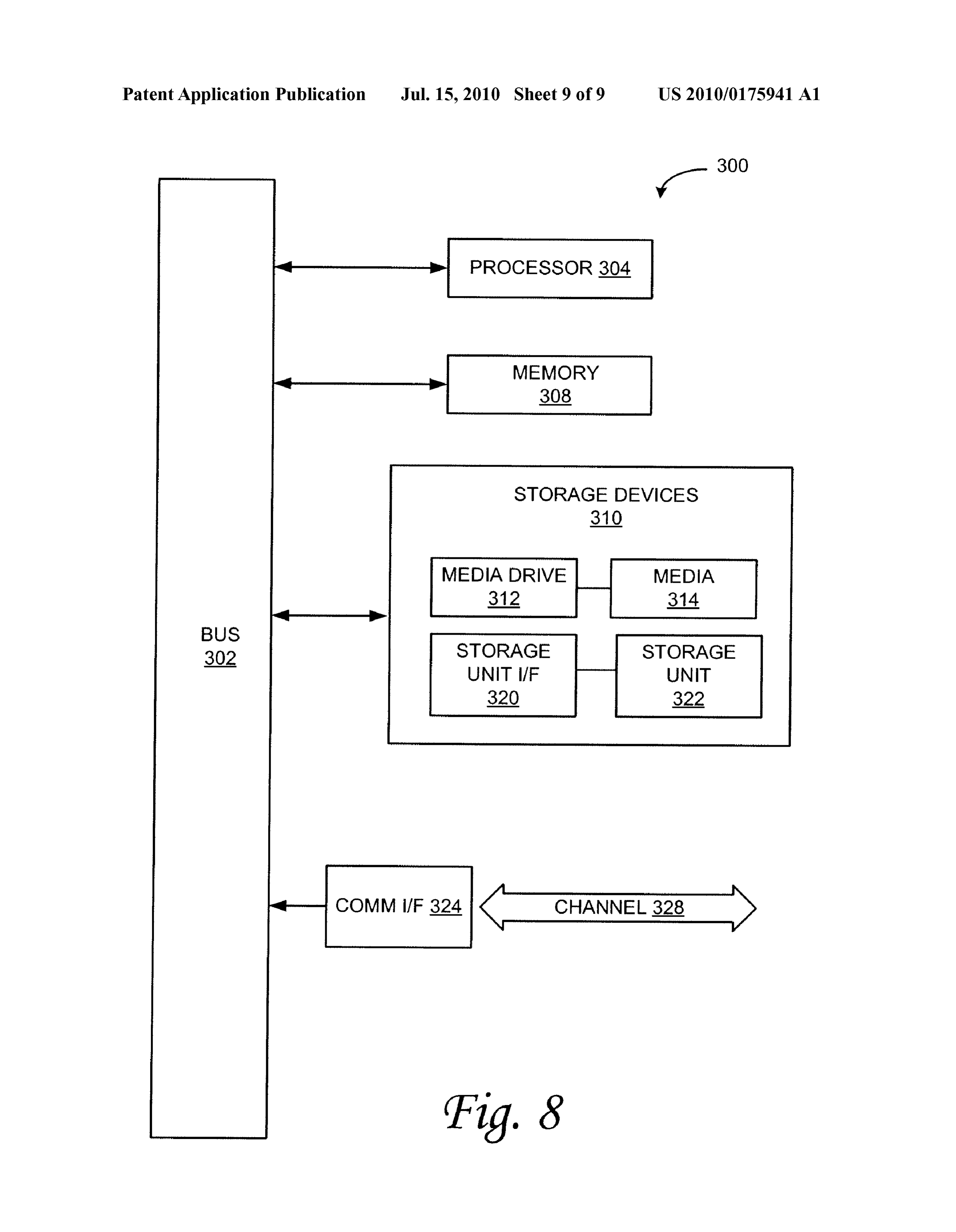
base frequencies. Those of ordinary skill in the art will appre 0065 Referring now to FIG. 8, computing module 300 ciate other harmonics or combinations of harmonics that may may represent, for example, computing or processing capa be used. For example, the 8686 Hz, harmonic might be omit bilities found within desktop, laptop and notebook comput ted. ers; hand-held computing devices (PDA's, Smartphones, cell 0061 Further examples may save energy by supplying the phones, palmtops, etc.); mainframes, Supercomputers, work high voltage only during the off periods of the UHF and VHF stations or servers; or any other type of special-purpose or waveforms. Because the electrolysis reaction takes place dur general-purpose computing devices as may be desirable or ing the active periods of the UHF and VHF waveforms, the appropriate for a given application or environment. Comput
Page 18
US 2010/0175941 A1 Jul. 15, 2010
ing module 300 might also represent computing capabilities ernet, network interface card, WiMedia, IEEE 802.XX or embedded within or otherwise available to a given device. For other interface), a communications port (such as for example, example, a computing module might be found in other elec a USB port, IR port, RS232 port Bluetooth R) interface, or tronic devices Such as, for example, digital cameras, naviga other port), or other communications interface. Software and tion systems, cellular telephones, portable computing data transferred via communications interface 324 might devices, modems, routers, WAPs, terminals and other elec typically be carried on signals, which can be electronic, elec tronic devices that might include Some form of processing tromagnetic (which includes optical) or other signals capable capability. of being exchanged by a given communications interface 324. 0066 Computing module 300 might include, for example, These signals might be provided to communications interface one or more processors, controllers, control modules, or other 324 via a channel 328. This channel 328 might carry signals processing devices, such as a processor 304. Processor 304 and might be implemented using a wired or wireless commu might be implemented using a general-purpose or special nication medium. These signals can deliver the Software and purpose processing engine Such as, for example, a micropro data from memory or other storage medium in one computing cessor, controller, or other control logic. In the example illus system to memory or other storage medium in computing trated in FIG. 8, processor 304 is connected to a bus 302, system 300. Some examples of a channel might include a although any communication medium can be used to facili phone line, a cellular link, an RF link, an optical link, a tate interaction with other components of computing module network interface, a local or wide area network, and other 300 or to communicate externally. wired or wireless communications channels. 0067 Computing module 300 might also include one or 0071. In this document, the terms “computer program more memory modules, simply referred to herein as main medium' and "computer usable medium' are used to gener memory 308. For example, preferably random access ally refer to physical storage media Such as, for example, memory (RAM) or other dynamic memory, might be used for memory 308, storage unit 320, and media 314. These and storing information and instructions to be executed by pro other various forms of computer program media or computer cessor 304. Main memory 308 might also be used for storing usable media may be involved in storing one or more temporary variables or other intermediate information during sequences of one or more instructions to a processing device execution of instructions to be executed by processor 304. for execution. Such instructions embodied on the medium, Computing module 300 might likewise include a read only are generally referred to as "computer program code' or a memory (“ROM) or other static storage device coupled to “computer program product' (which may be grouped in the bus 302 for storing static information and instructions for form of computer programs or other groupings). When processor 304. executed, such instructions might enable the computing mod 0068. The computing module 300 might also include one ule 300 to perform features or functions of the present inven or more various forms of information storage mechanism tion as discussed herein.
310, which might include, for example, a media drive 312 and 0072 While various embodiments of the present invention a storage unit interface 320. The media drive 312 might have been described above, it should be understood that they include a drive or other mechanism to support fixed or remov have been presented by way of example only, and not of able storage media 314. For example, a hard disk drive, a limitation. Likewise, the various diagrams may depict an floppy disk drive, a magnetic tape drive, an optical disk drive, example architectural or other configuration for the invention, a CD or DVD drive (R or RW), or other removable or fixed which is done to aid in understanding the features and func media drive might be provided. Accordingly, storage media tionality that can be included in the invention. The invention 314, might include, for example, a hard disk, a floppy disk, is not restricted to the illustrated example architectures or magnetic tape, cartridge, optical disk, a CD or DVD, or other configurations, but the desired features can be implemented fixed or removable medium that is read by, written to or using a variety of alternative architectures and configurations. accessed by media drive 312. As these examples illustrate, the Indeed, it will be apparent to one of skill in the art how storage media 314 can include a computer usable storage alternative functional, logical or physical partitioning and medium having stored therein computer software or data. configurations can be implemented to implement the desired 0069. In alternative embodiments, information storage features of the present invention. Also, a multitude of differ mechanism 310 might include other similar instrumentalities ent constituent module names other than those depicted for allowing computer programs or other instructions or data herein can be applied to the various partitions. Additionally, to be loaded into computing module 300. Such instrumentali with regard to flow diagrams, operational descriptions and ties might include, for example, a fixed or removable storage method claims, the order in which the steps are presented unit 322 and an interface 320. Examples of such storage units herein shall not mandate that various embodiments be imple 322 and interfaces 320 can include a program cartridge and mented to perform the recited functionality in the same order cartridge interface, a removable memory (for example, a flash unless the context dictates otherwise. memory or other removable memory module) and memory 0073. Although the invention is described above in terms slot, a PCMCIA slot and card, and other fixed or removable of various exemplary embodiments and implementations, it storage units 322 and interfaces 320 that allow software and should be understood that the various features, aspects and data to be transferred from the storage unit 322 to computing functionality described in one or more of the individual module 300. embodiments are not limited in their applicability to the par 0070 Computing module 300 might also include a com ticular embodiment with which they are described, but munications interface 324. Communications interface 324 instead can be applied, alone or in various combinations, to might be used to allow software and data to be transferred one or more of the other embodiments of the invention, between computing module 300 and external devices. whether or not such embodiments are described and whether Examples of communications interface 324 might include a or not such features are presented as being a part of a modem or Softmodem, a network interface (Such as an Eth described embodiment. Thus, the breadth and scope of the
Page 19
US 2010/0175941 A1 Jul. 15, 2010
present invention should not be limited by any of the above wherein the third signal generator comprises a second out described exemplary embodiments. put electrically coupled to the electrolysis device con 0074 Terms and phrases used in this document, and varia figured to provide the second output signal Superim tions thereof, unless otherwise expressly stated, should be posed with the first output signal to the electrolysis construed as open ended as opposed to limiting. As examples device;
of the foregoing: the term “including should be read as and wherein the second output signal is configured to be meaning “including, without limitation” or the like; the term used by the electrolysis device to charge electrodes dis “example' is used to provide exemplary instances of the item posed in the electrolysis device in electrolytic formation in discussion, not an exhaustive or limiting list thereof; the of hydrogen and oxygen gasses from water. terms “a” or “an should be read as meaning “at least one.” “one or more' or the like; and adjectives such as “conven 3. The apparatus of claim 1, wherein the second signal tional,” “traditional,” “normal,” “standard,” “known and generator generates the output signal from data received from terms of similar meaning should not be construed as limiting a plurality of sensors.
the item described to a given time period or to an item avail 4. The apparatus of claim 1, wherein the waveform further able as of a given time, but instead should be read to encom comprises a pulse wave.
pass conventional, traditional, normal, or standard technolo 5. The apparatus of claim 2, gies that may be available or known now or at any time in the wherein the second output signal comprises a high Voltage future. Likewise, where this document refers to technologies waveform with the same frequency as the first output that would be apparent or known to one of ordinary skill in the signal;
art, such technologies encompass those apparent or known to the skilled artisan now or at any time in the future. and wherein the second output signal is phase shifted with 0075. The presence of broadening words and phrases such first output signal Such that as "one or more.” “at least,” “but not limited to’ or other like the second output signal is at a low Voltage when the first phrases in some instances shall not be read to mean that the output signal is at a high Voltage, and narrower case is intended or required in instances where Such the second output signal is at a high Voltage when the first broadening phrases may be absent. The use of the term 'mod output signal is at a low Voltage. ule' does not imply that the components or functionality 6. The apparatus of claim 3, wherein the sensors provide described or claimed as part of the module are all configured data from operation parameters of an engine. in a common package. Indeed, any or all of the various com ponents of a module, whether control logic or other compo 7. The apparatus of claim 6, wherein the sensors further nents, can be combined in a single package or separately provide data from operation parameters of the electrolysis device.
maintained and can further be distributed in multiple group ings or packages or across multiple locations. 8. The apparatus of claim 1, wherein the frequency of the 0076. Additionally, the various embodiments set forth output signal is within the range of 40 kHz to 45 KHZ or is herein are described in terms of exemplary block diagrams, within the range of 140 kHz to 150 kHz. flow charts and other illustrations. As will become apparent to 9. The apparatus of claim 9, wherein one of ordinary skill in the art after reading this document, the the second signal generator is further configured to output illustrated embodiments and their various alternatives can be a first Subharmonic output signal, the first Subharmonic implemented without confinement to the illustrated output signal having a frequency that Subharmonic of the examples. For example, block diagrams and their accompa frequency of the first output signal, and nying description should not be construed as mandating a the output is further configured to provide the first Subhar particular architecture or configuration. monic output signal to the electrolysis device Superim 1. A signal generating apparatus, comprising: posed with the first output signal. a first signal generator configured to generate a time vary 10. The apparatus of claim 2, wherein the frequency of the ing signal; and first output signal is within the range of 40 kHz to 45 kHz and a second signal generator electrically coupled to the first the frequency of the second output signal is within the range signal generator configured to generate an output signal of 140 kHZ to 150 kHZ.
using the time varying signal, the output signal having a 11. The apparatus of claim 10, wherein waveform comprising a minimum Voltage, a maximum the second signal generator is further configured to output Voltage, a frequency, and a duty cycle;
wherein the second signal generator comprises an output a first Subharmonic output signal, the first Subharmonic electrically coupled to an electrolysis device configured output signal having a frequency that is a Subharmonic to provide the output signal to the electrolysis device; of the frequency of the first output signal; and and the third signal generator is further configured to output a wherein the output signal is configured to be used by the second Subharmonic output signal, the second Subhar electrolysis device to charge electrodes disposed in the monic output signal having a frequency that is a Subhar electrolysis device in electrolytic formation of hydrogen monic of the frequency of the second output signal; and and oxygen gasses from water. wherein the first and second outputs are further configured 2. The apparatus of claim 1, to provide the first and second Subharmonic output sig further comprising a third signal generator electrically nals to the electrolysis device superimposed with the coupled to the first signal generator configured to gen first and second output signals.
erate a second output signal having a waveform com 12. The apparatus of claim 3, wherein the second signal prising a minimum Voltage, a maximum Voltage, a fre generator varies the duty cycle output signal based on the quency, and a duty cycle; data.
Page 20
US 2010/0175941 A1 Jul. 15, 2010
13. A method for providing an electrical signal for an 23. A vehicle with a hydrogen gas injection system, com electrolysis device, comprising: pr1S1ng:
generating a time varying signal; a generator electrically coupled to an electrolysis device; generating an output signal using the time varying signal, and the output signal having a waveform comprising a mini the electrolysis device coupled to an air intake manifold; mum Voltage, a maximum Voltage, a frequency, and a wherein the generator comprises:
duty cycle; a first signal generator configured to generate a time providing the output signal to an electrolysis device; Varying signal; and using the output signal to charge electrodes disposed in the a second signal generator electrically coupled to the first electrolysis device in electrolysis of water into hydrogen signal generator configured to generate an output sig and oxygen gasses. nal using the time varying signal, the output signal 14. The method of claim 13, further comprising, having a waveform comprising a minimum Voltage, a generating a second output signal having a waveform com maximum Voltage, a frequency, and a duty cycle; prising a minimum Voltage, a maximum Voltage, a fre wherein the second signal generator comprises an output quency, and a duty cycle; electrically coupled to the electrolysis device config providing the second output signal Superimposed with the ured to provide the output signal to the electrolysis first output signal to the electrolysis device; device; and using the second output signal to charge electrodes dis and wherein the electrolysis device is configured togen posed in the electrolysis device in electrolysis of water erate hydrogen gas from water using the output signal into hydrogen and oxygen gasses. to charge electrodes disposed in the electrolysis 15. The method of claim 13, further comprising device in electrolytic formation of hydrogen and oxy receiving data from a plurality of sensors of operation gen gasses from water, and to provide the hydrogen parameters of the engine or the electrolysis device; and gas the air intake manifold. generating the output signal from the data. 24. The apparatus of claim 23, 16. The method of claim 13, wherein the waveform further wherein the generator further comprises a third signal gen comprises a pulse wave. erator electrically coupled to the first signal generator 17. The method of claim 14, configured to generate a second output signal having a wherein the second output signal comprises a high Voltage waveform comprising a minimum Voltage, a maximum waveform with the same frequency as the first output Voltage, a frequency, and a duty cycle; signal; wherein the third signal generator comprises a second out and wherein the second output signal is phase shifted with put electrically coupled to the electrolysis device con first output signal Such that figured to provide the second output signal Superim the second output signal is at a low Voltage when the first posed with the first output signal to the electrolysis output signal is at a high Voltage, and device;
the second output signal is at a high Voltage when the and wherein the electrolysis device is configured to use the first output signal is at a low Voltage. second output signal to charge electrodes disposed in the 18. The method of claim 13, wherein the frequency is electrolysis device in electrolytic formation of hydrogen within the range of 40 KHZ to 45 KHZ or is within the range and oxygen gasses from water. of 140 KHZ to 150 KHZ. 25. The apparatus of claim 23, 19. The method of claim 18, further comprising, further comprising a plurality of sensors disposed in the generating a first Subharmonic output signal, the first Sub vehicle to provide data to the generator, wherein the harmonic output signal having a frequency that Subhar sensors provide data from operation parameters of an monic of the frequency of the first output signal, and engine or from operation parameter of the electrolysis providing the first Subharmonic output signal to the elec device; and trolysis device Superimposed with the first output signal. wherein the generator is further configured to use the data to generate the output signal.
20. The method of claim 14, wherein the frequency of the 26. The apparatus of claim 23, wherein the frequency of the first output signal is within the range of 40 kHz to 45 kHz and output signal is within the range of 40 KHZ to 45 KHZ or is the frequency of the second output signal is within the range within the range of 140 KHZ to 150 KHZ.
27. The apparatus of claim 24, wherein the generator varies 21. The method of claim 20, further comprising, the duty cycle of the output signal based on the data. generating a first Subharmonic output signal, the first Sub 28. The apparatus of claim 24, harmonic output signal having a frequency that is S wherein the second output signal comprises a high Voltage Subharmonic of the frequency of the first output signal; waveform with the same frequency as the first output generating a second Subharmonic output signal, the second signal;
Subharmonic output signal having a frequency that is a and wherein the second output signal is phase shifted with Subharmonic of the frequency of the second output sig first output signal Such that nal; and the second output signal is at a low Voltage when the first providing the first and second Subharmonic output signals output signal is at a high Voltage, and to the electrolysis device superimposed with the first and the second output signal is at a high Voltage when the second output signals. first output signal is at a low Voltage. 22. The method of claim 15, further comprising varying the duty cycle of the output signal based on the data. c c c c c
Provenance
- Collection
- Patents citing this work
- Pages
- 20
- Method
- pdftotext (the PDF's own text layer) + pdftoppm 300dpi page scans
- Patent office record
- patents.google.com →
- Source
- Google Patents citing-documents table
- Assignee
- Mohammed Khodabakhsh
- Inventors
- Mohammed Khodabakhsh
- Published
- 2010-07-15
- Transcribed from
- patentimages.storage.googleapis.com →