patent · US3485742
Pressure responsive control circuit for an electrolysis-type hydrogen generator
23 December 1969
Page 1
Drawing sheet — no readable text.
Page 2
United States Patent Office 3,485,742 Patented Dec. 23, 1969
3,485,742 manometer pressure gauge, a transistorized relay circuit PRESSURE RESPONSIVE CONTROL CIRCUIT responsive to the photo-electric cell of the pressure FOR AN ELECTROLYSS-TYPE HYDROGEN gauge, and a current regulating means controlled by GENERATOBR the relay circuit for controlling the current supplied to Karl H. Emich, Decatur, and Richard E. Wiley, Tuscola, the electrodes of the hydrogen generator. The overall Ali., assignors to National Distillers & Chemical Corpo arrangement is simple in design, relatively free of moving ration, New York, N.Y. parts, and permits easy adjustment of the desired hydro Filed May 10, 1967, Ser. No. 637,511 gen output pressure which is to be maintained. Experi Int, C. B0k 3/00 mental results show that the control circuit of this in
vention maintains the output pressure to within -t-.015 inch of water, whereas the most accuracy that could be
ABSTRACT OF THE DISCLOSURE achieved with the prior art arrangements was -c.35 inch of water.
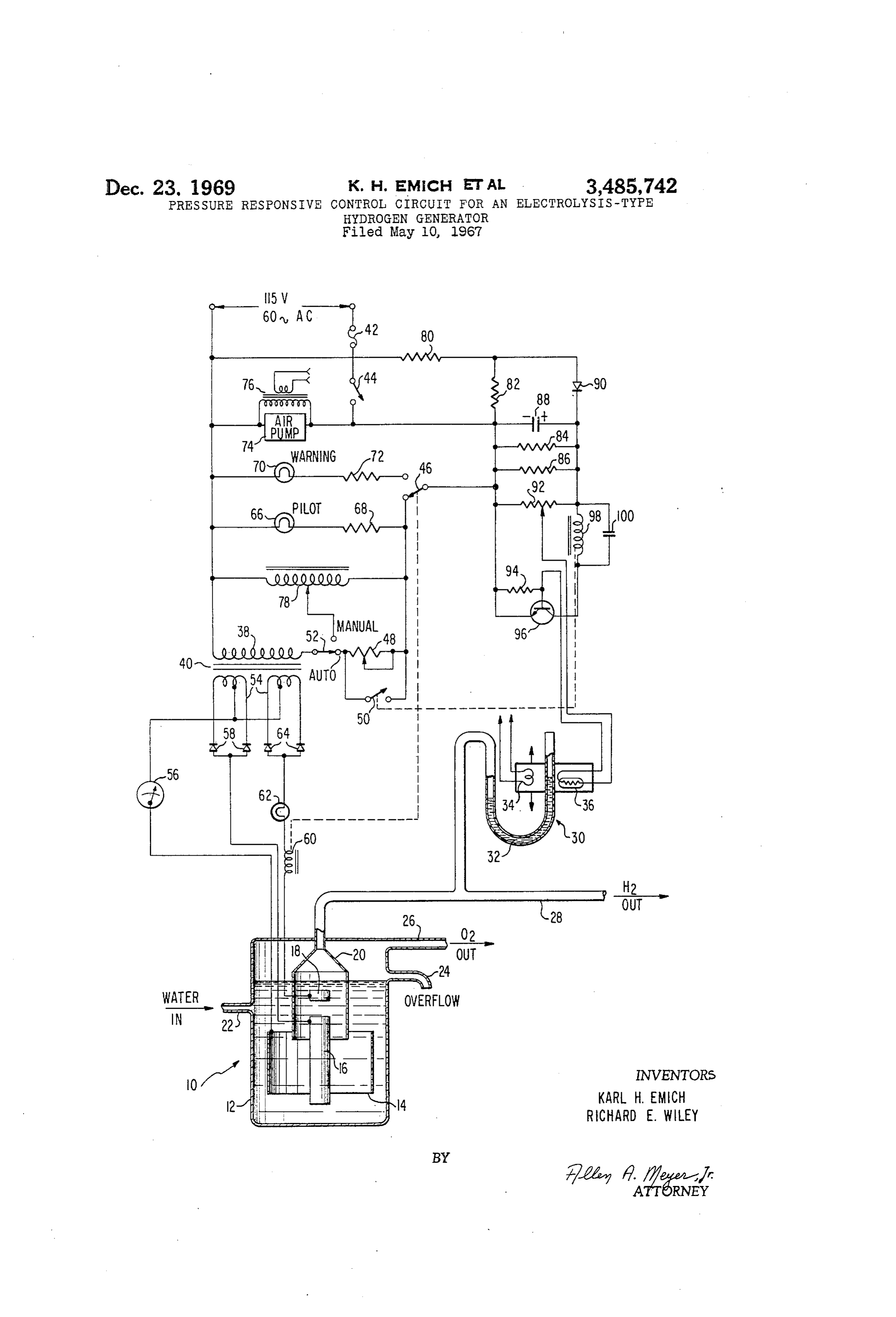
An electronic circuit for controlling the current Sup plied to an electrolysis-type hydrogen generator in re BRIEF EDESCRIPTION OF THE DRAWINGS sponse to the pressure of the generated hydrogen. The The foregoing and other objects, features and advan level of the liquid in a manometer pressure gauge is tages of the invention will be apparent from the follow sensed by a light bulb-photocell, and the voltage drop ing more particular description of a preferred embodi across the photocell controls the conduction of a tran ment of the invention, as illustrated in the accompanying sistor in a relay circuit. The relay controls the current 20 drawings, in which the single figure shows a schematic through the primary winding of a transformer whose diagram of the electronic control circuit of this invention. secondary winding supplies current to the hydrogen gen DESCRIPTION OF THE PREFERRED erator electrodes.
EMBODIMENT
Referring to the drawing, hydrogen is produced in an
CROSS-REFERENCES TO RELATED PATENTS 25 electrolysis-type generator 10 which includes a fluid
container 12, a ring-shaped anode 14, shown in cutaway, on Aug. 16, 1966, and entitled. "Method for Detecting a rod-shaped cathode 16, an auxiliary cathode 18 and a funnel-shaped hydrogen collector 20. Water is admitted
Volatile Organic Contaminants in Reuseable Containers.” 30 to the container at 22 and rises to the level of the over BACKGROUND OF THE INVENTION flow line 24. The particular generator 10 shown forms no This invention relates in general to hydrogen gener part of the present invention and any suitable type of ators and more particularly to a novel electronic circuit electrolysis generator known in the art could be used. for controlling the magnitude of the current supplied Oxygen is taped off from the top of the container at 26 to the electrodes of such a generator in response to the and the hydrogen produced is drained of via output generated gas pressure. line 28 which leads to a utilization device, in this case Hydrogen generators of the electrolysis type are well a flame detector as described in the above referenced known in the prior art and generally involve the passage patent. A branch in the output line 28 communicates With a U tube manometer pressure gauge 30 filled with of an electric current between spaced electrodes disposed 40 a Suitable in an aqueous solution. The current ionizes the water liquid 32, such as water. The level of the molecules and the positively charged hydrogen ions liquid in one arm of the tube is sensed by a light bulb 34 migrate to the negative electrode or cathode while the cooperating with a photocell 36. The housing containing negatively charged oxygen ions collect on the positive the bulb and the photocell is slidable up and down the electrode or anode. The hydrogen ions undergo a re tube arm to adjust the hydrogen pressure level as will be more apparent later on.
duction at the cathode as they acquire electrons to Power is Suplied to the system from a 115 volt 60 neutralize their positive charges, form bubbles of hydro Cycle AC source as shown and flows to the primary wind gen gas, and rise to the surface of the liquid where they ing 38 of power transformer 40 through the path in may be collected and drained off. cluding fuse 42, on-off switch 44, relay switch 46, either When such generators are used to supply hydrogen to a flame detector, as in the contamination detection system 50 potentiometer 52. The Split 48 or relay switch 50, and option switch secondary windings 54 of transformer 40 disclosed in the above referenced patent, the hydrogen are connected to the anode 14 of hydrogen generator demand of the detector depends on a number of vari 10 through an ammeter 56, which may be calibrated to able factors, including the ambient temperature. In the yield an instantaneous indication of the rate of hydrogen past, it has been proposed to regulate the hydrogen gen generation in milliliters per minute. One of the secondary erator output in response to the demand of the system by Sensing the hydrogen pressure in the output line of windings 54 is connected directly to cathode 16 through the generator, which varies in direct proportion to de isdiode rectifiers 58, while the other secondary winding 54 mand, and controlling the current through the gener 60, a currenttoregulating connected auxiliary cathode 18 through a relay coil lamp 62 and diode rectifiers 64.
ator in response to the pressure. Many problems have In normal operation, with on-off switch 44 closed, a been encountered in implementing such an arrangement, 60 pilot light 66 is energized through resistor 68. If the water however, in that the usual pressure sensing devices are Supply is interrupted, however, and the level in con too insensitive and the current control means have too much inertia or output lag. The result is that the output tainer
12 falls below auxiliary cathode 18, relay coil deemergized and its associated switch 46 transfers pressure tends to hunt or oscillate about the desired level over a dangerously wide range, which often produces energizes a warningwhich to its uper contact, extinguishes pilot light 66 and light 70 through resistor 72, thereby a run-away condition and system shutdown or failure. Signalling the operator of the low water condition. SUMMARY OF THE INVENTION An air pump 74 is also connected across the AC This invention overcomes the problems outlined above Power Supply to draw air samples into the contamina by. providing a novel hydrogen generator control cir 70 tion detection apparatus. A transformer 76 is connected across the air pump to supply an energizing signal to light cuit characterized by a photoelectrically detected liquid bulb 34 at the manometer. Manual control of the hy
Page 3
drogen generator 10 may be effected by transferring for regulating the current supplied to the electrodes option Switch 52 from its automatic to its manual con of the hydrogen generator, whereby the generator tact and adjusting auto transformer 78. current is regulated in response to the hydrogen out Resistors 80, 82, 84 and 86, capacitor 88 and diode put preSSure.
90 constitute a DC power supply network for the tran 5 2. A pressure responsive control circuit as defined in sistorized relay control circuit including potentiometer claim 1 wherein the photo-electrically sensed pressure 92, biasing resistor 94, NPN transistor 96, relay coil 93 gauge comprises:
and capacitor 100. (a) a liquid filled U tube manometer having one end In operation, assume that the demand of the flame de of the tube connected to the output line of the gen tector temporarily increases, drawing off a greater volume 10 erator, of hydrogen and thus lowering the hydrogen pressure. (b) a light source disposed on one side of one arm The liquid level of the manometer tube then drops and the of the tube, photocell 36 is illuminated by light source 34. This (c) a photocell disposed on the other side of the one lowers the resistance of the photocell to the kilohm range arm of the tube opposite the light source, and which increases the positive bias on the base of tran 5 (d) means for sliding the light source and photo sistor 96, rendering the latter conductive. Relay coil 98 cell up or down the one arm of the tube together. is thus energized and transfers its associated Switch arm 3. A pressure responsive control circuit as defined in 50 to the closed position. This short circuits poten claim 1 wherein the means recited in sub-paragraph (c) tiometer 48 which increases the current through the includes a potentiometer and a relay controlled switch primary winding of transformer 40 and causes a corre 20 connected in parallel.
spondingly greater current to flow through secondary 4. A pressure responsive control circuit as defined in windings 54 to the hydrogen generator electrodes 14, claim wherein the power source is an alternating current 16 and 18. The hydrogen output of the generator is thus source, and further comprising a power supply network increased, the hydrogen pressure increases, and the liquid connected between the power source and the relay circuit 32 in the manometer tube rises to once more block the 25 for supplying regulated DC power to the latter, and light source from photocell 36. wherein the relay circuit comprises a transistor and a The circuit now cycles in the reverse direction with relay coil connected in series and the photo-electric sensor the resistance of the photocell increasing to the megohm of the pressure gauge is connected to the base of the range to lower the bias on transistor 96 and render the transistor.
latter nonconductive. Relay coil 98 is de-energized, opens 30 5. A pressure responsive control circuit as defined in its switch arm 50, and the potentiometer 48 is again claim 4 wherein the photo-electrically sensed pressure placed in the circuit to reduce the current through trans gauge comprises:
former 40 and ultimately reduce the hydrogen output. (a) a liquid filled U tube manometer having one end The circuit continuously cycles in the manner de of the tube connected to the output line of the gen cribed above over a range of .03 inch of water, which is 35 erator, well within the acceptable variation limits for most re (b) a light source disposed on one side of one arm quirements. It would, of course, be possible to include of the tube, and damping or rate means in the circuit as well as integrat (c) a photocell disposed on the other side of the one ing or reset means to cause the hydrogen pressure to arm of the tube opposite the light source. accurately track the demand, as is well known in the 40 claim6. A pressure responsive control circuit as defined in servo arts, and the provision of such additional means 5 wherein the means recited in sub-paragraph (c } is intended to be within the scope of this invention. of claim 1 includes a potentiometer and a relay controlled While the invention has been particularly shown and switch connected in parallel.
described with reference to preferred embodiments there References Cited of, it will be understood by those skilled in the art that various changes in form and details may be made there UNITED STATES PATENTS in without departing from the spirit and Scope of the 2,118,029 5/1938 Boyd ----------- 73-401 XR invention. 2,555,674 6/1951 Carrick ---------- 73-432 XR What is claimed is: 2,875,141 2/1959 Noyce --------- 204-228 XR 1. A pressure responsive control circuit for an electro 3,336,215 8/1967 Hagen ------------- 204-230 lysis-type hydrogen generator having anode and cathode electrodes and means for collecting generated hydrogen FOREIGN PATENTS gas and supplying same to an output line, and including 742,201 9/1966 Canada. a source of electrical power and conversion means for coupling the power source to the electrodes, comprising: JOHN H. MACK, Primary Examiner (a) a photo-electrically sensed pressure gauge con D. R. VALENTINE, Assistant Examiner nected to the output line of the generator, (b) a transistor controlled relay circuit responsive to U.S. C. X.R.
the photo-electric sensor of the pressure gauge, and (c) means controlled by the relay circuit connected 60 73-432; 204-228 between the power source and the conversion means
Provenance
- Collection
- Cited prior art
- Original PDF
- patentimages.storage.googleapis.com →
- Filed
- 1967-05-10
- Pages
- 3
- Method
- pdftotext (the PDF's own text layer) + pdftoppm 300dpi page scans
- Source
- Google Patents bibliographic record
- Granted
- 1969-12-23
- Inventors
- Karl H Emich; Richard E Wiley; National Distillers and Chemical Corp
- Transcribed from
- patentimages.storage.googleapis.com →