patent · US3755128
Electrolysis system and method
28 August 1973
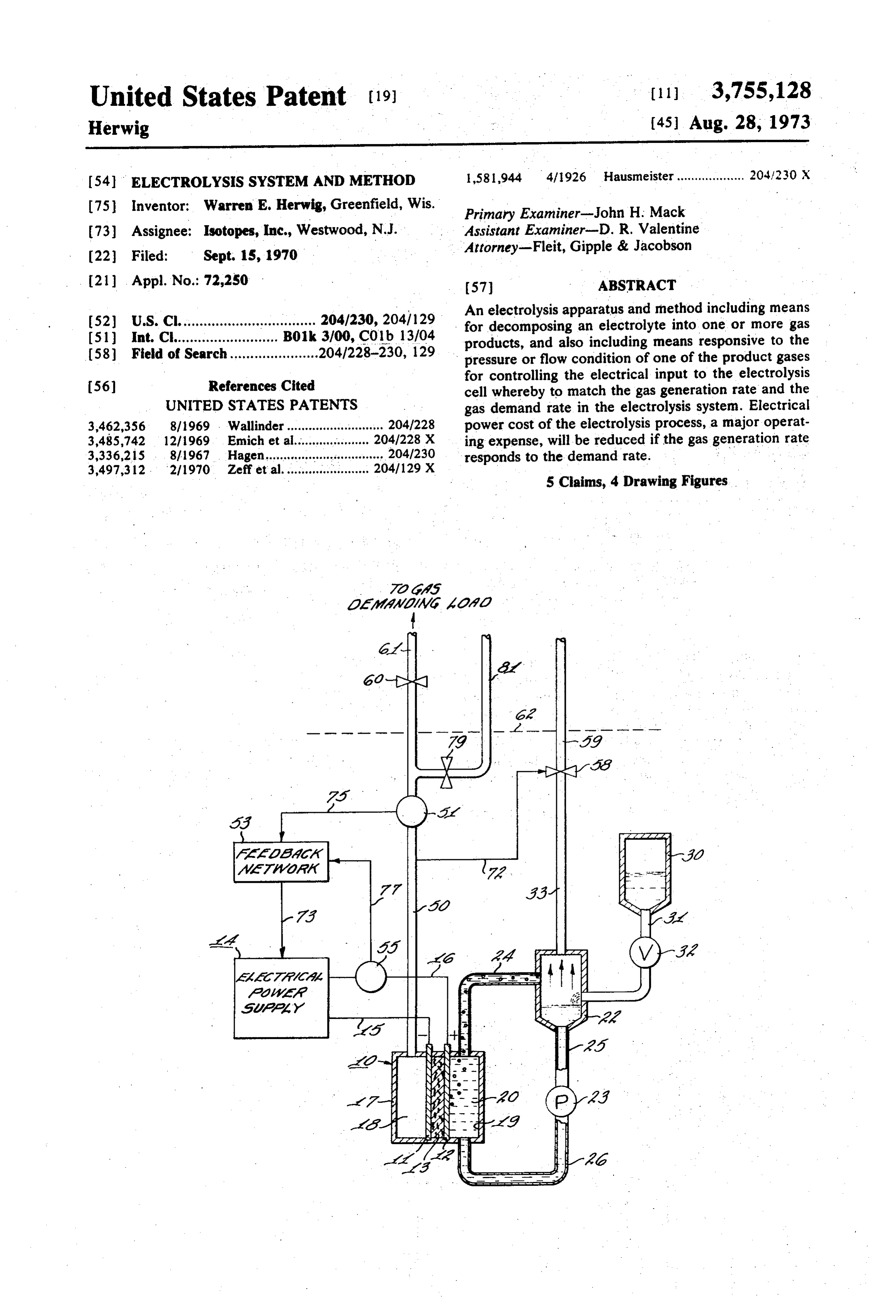
Page 1 — bibliographic record
United States Patent (19) (11) 3,755,128 Herwig (45) Aug. 28, 1973 (54) ELECTROLYSIS SYSTEM AND METHOD 1,581,944 4/1926 Hausmeister................... 2041230 X 75 Inventor: Warren E. Herwig, Greenfield, Wis. Primary Examiner-John H. Mack (73) Assignee: Isotopes, Inc., Westwood, N.J. Assistant Examiner-D. R. Valentine (22) Filed: Sept. 15, 1970 Attorney-Fleit, Gipple & Jacobson (21) Appl. No.: 72,250 57 ABSTRACT An electrolysis apparatus and method including eas : E. Sim a Boik 29.3 for decomposing an electrolyte into one or more gas (58) Field of search?h d 8 08 0 w w w 26:28-230. 129 products, and also including means responsive to the 8 8 8 v8 0eo os 9 pressure or flow condition of one of the product gases for controlling the electrical input to the electrolysis (56) References Cited cell whereby to match the gas generation rate and the UNITED STATES PATENTS gas demand rate in the electrolysis system. Electrical 3,462,356 8/1969 Wallinder........................... 204/228 power cost of the electrolysis process, a major operat
ing expense, will be reduced if the gas generation rate 3,497,312. 2/1970 Zeff et al........................ g; responds to the demand rate. 5 Claims, 4 Drawing Figures.
Page 2
Drawing sheet — no readable text.
Page 3
Drawing sheet — no readable text.
Page 4
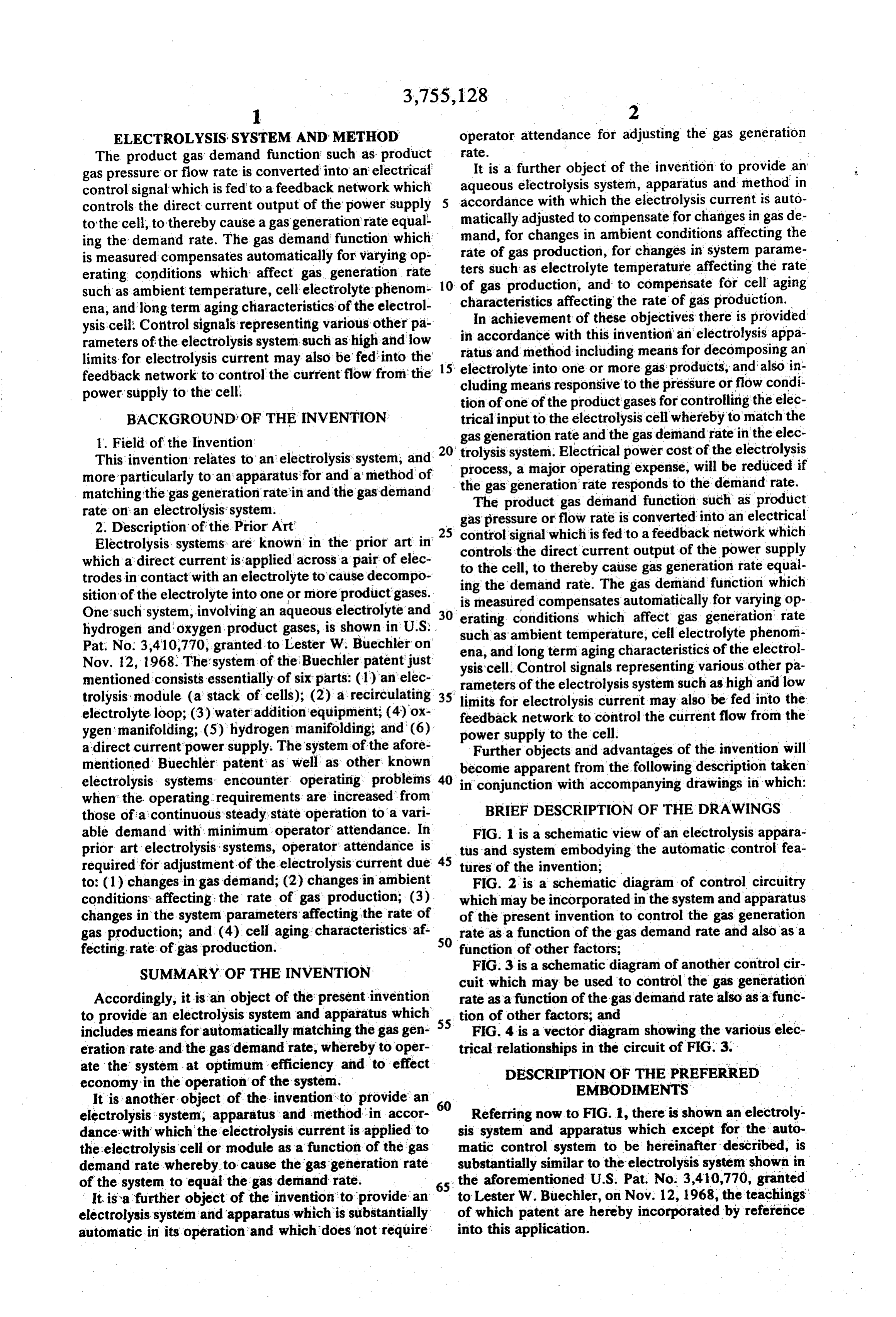
ELECTROLYSIS.SYSTEM AND METHOD operator attendance for adjusting the gas generation The product gas demand function such as product rate.
gas pressure or flow rate is converted into an electrical It is a further object of the invention to provide an aqueous electrolysis system, apparatus and method in control signal which is fed to a feedback network which accordance with which the electrolysis current is auto controls the direct current output of the power supply 5 matically adjusted to compensate for changes in gas de to the cell, to thereby cause a gas generation rate equal ing the demand rate. The gas demand function which mand, for changes in ambient conditions affecting the is measured compensates automatically for varying op rate of gas production, for changes in system parame erating conditions which affect gas generation rate 10. ters
such as electrolyte temperature affecting the rate gas production, and to compensate for cell aging such as ambient temperature, cell electrolytephenom ena, and long term aging characteristics of the electrol characteristics affecting the rate of gas production. ysis-cell. Control signals representing various other pa in accordance withofthis
In achievement these objectives there is provided invention an electrolysis appa rameters of the electrolysis system such as high and low limits for electrolysis current may also be fed into the ratus and method including means for decomposing an feedback network to control the current flow from the 15 electrolyte into one or more gas products, and also in power supply to the cell. cluding means responsive to the pressure or flow condi tion of one of the product gases for controlling the elec
BACKGROUND OF THE INVENTION trical input to the electrolysis cell whereby to match the 1. Field of the Invention gas generation rate and the gas demand rate in the elec This invention relates to an electrolysis system, and 20 process,system.
trolysis Electrical power cost of the electrolysis more particularly to an apparatus for and a method of the gas generationoperating a major rate expense, will be reduced if responds to the demand rate.
matching the gas generation rate in and the gas demand The product gas demand function such as product rate on an electrolysis system. gas pressure or flow rate is converted into an electrical 2. Description of the Prior Art 25 control signal which is fed to a feedback network which Electrolysis systems are known in the prior art in which a direct current is applied across a pair of elec controls to the the direct current output of the power supply cell, to thereby cause gas generation rate equal trodes in contact with an electrolyte to cause decompo ing the demand rate. The gas demand function which sition of the electrolyte into one or more product gases. is measured compensates automatically for varying op One'such system, involving an aqueous electrolyte and 30 erating conditions which affect gas generation rate hydrogen and oxygen product gases, is shown in U.S. such as ambient temperature, cell electrolyte phenom Pat. No. 3,410,770, granted to Lester W. Buechler on ena, and long term aging characteristics of the electrol Nov. 12, 1968. The system of the Buechler patent just ysis cell. Control signals representing various other pa mentioned consists essentially of six parts: (1) an elec rameters of the electrolysis system such as high and low trolysis module (a stack of cells); (2) a recirculating 35 limits for electrolysis current may also be fed into the electrolyte loop; (3) water addition equipment; (4) ox feedback network to control the current flow from the ygen manifolding; (5) hydrogen manifolding; and (6) power supply to the cell.
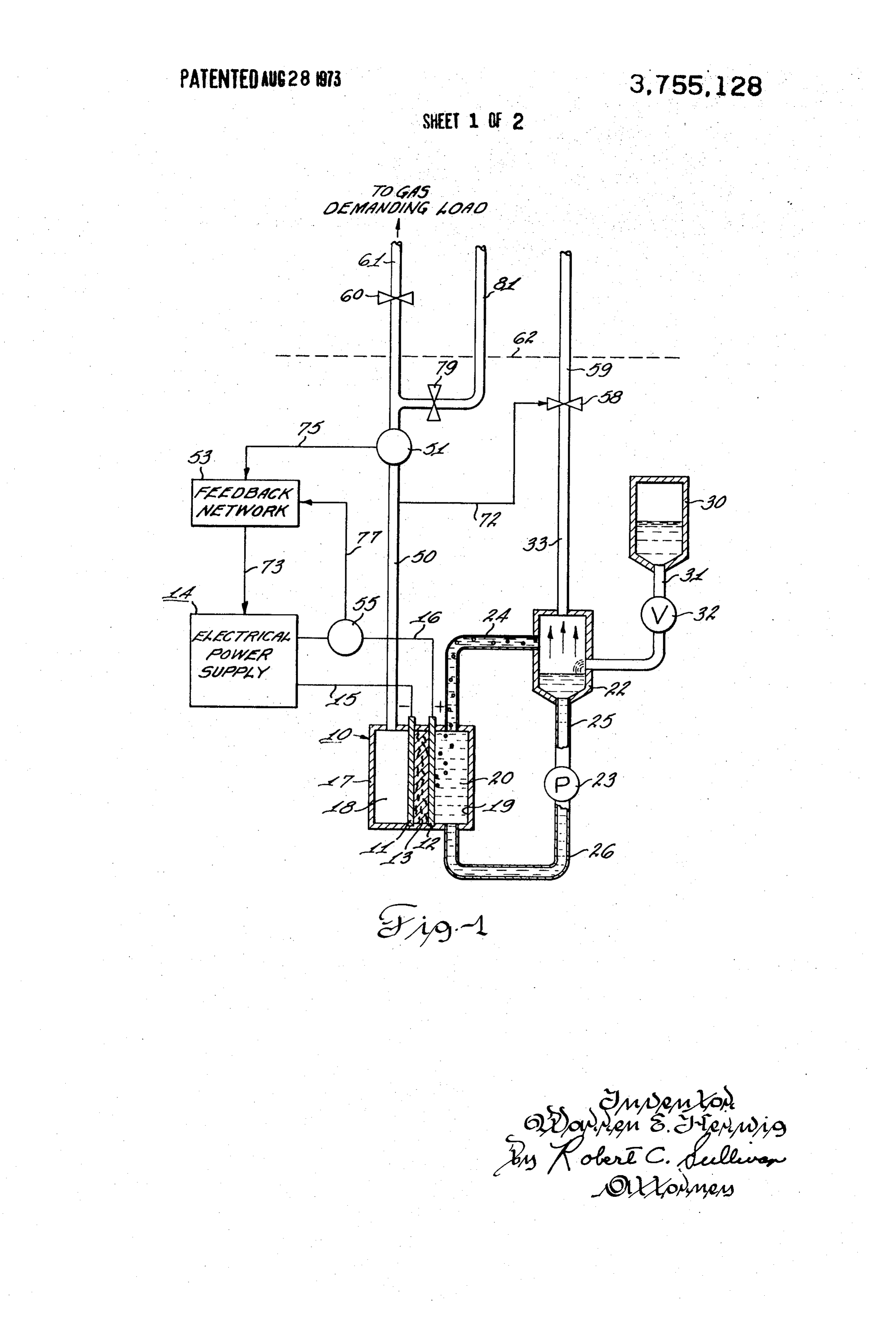
a direct current power supply. The system of the afore Further objects and advantages of the invention will mentioned Buechler patent as well as other known become apparent from the following description taken electrolysis systems, encounter operating problems 40 in conjunction with accompanying drawings in which: when the operating requirements are increased from those of a continuous steady state operation to a vari BRIEF DESCRIPTION OF THE DRAWINGs able demand with minimum operator attendance. In FIG. 1 is a schematic view of an electrolysis appara prior art electrolysis systems, operator attendance is 45 tus and system embodying the automatic control fea required for adjustment of the electrolysis current due tures of the invention;
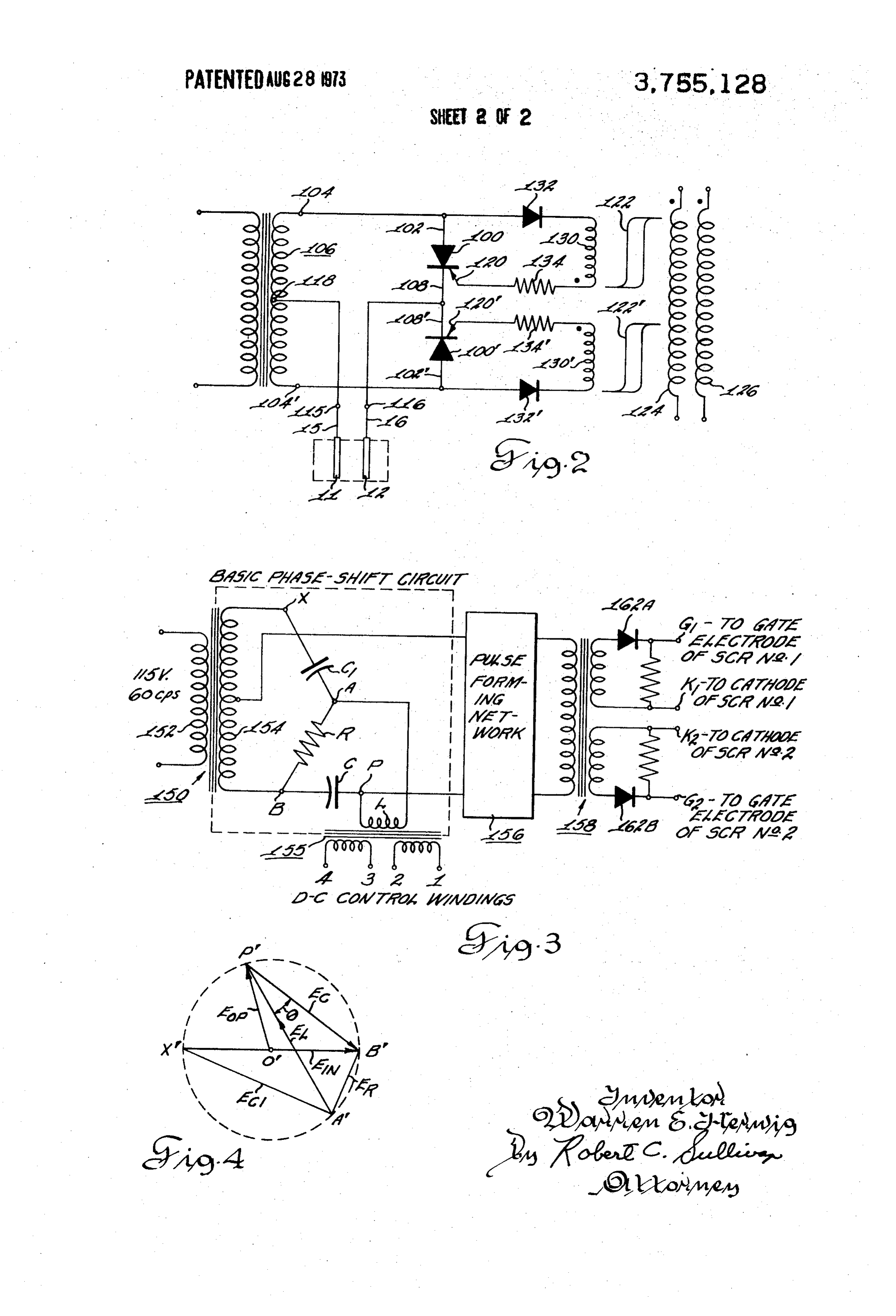
to: (1) changes in gas demand; (2) changes in ambient FIG. 2 is a schematic diagram of control circuitry conditions affecting: the rate of gas production; (3). which may be incorporated in the system and apparatus changes in the system parameters affecting the rate of of the present invention to control the gas generation gas production; and (4) cell aging characteristics af. 50 rate as a function of the gas demand rate and also as a fecting rate of gas production. function of other factors;
SUMMARY OF THE INVENTION FIG. 3 is a schematic diagram of another control cir cuit which may be used to control the gas generation
Accordingly, it is an object of the present invention rate as a function of the gas demand rate also as a func to provide an electrolysis system and apparatus which 55 tion of other factors; and includes means for automatically matching the gas gen FIG. 4 is a vector diagram showing the various elec eration rate and the gas demand rate, whereby to oper trical relationships in the circuit of FIG. 3. ate the system, at optimum efficiency and to effect DESCRIPTION OF THE PREFERRED economy in the operation of the system. EMBODEMENTS
It is another object of the invention to provide an 60 electrolysis system, apparatus and method in accor Referring now to FIG. 1, there is shown an electroly dance with which the electrolysis current is applied to sis system and apparatus which except for the auto the electrolysis cell or module as a function of the gas matic control system to be hereinafter described, is demand rate whereby to cause the gas generation rate substantially similar to the electrolysis system shown in of the system to equal the gas demand rate. 65 the aforementioned U.S. Pat. No. 3,410,770, granted It is a further object of the invention to provide an to Lester W. Buechler, on Nov. 12, 1968, the teachings electrolysis system and apparatus which is substantially of which patent are hereby incorporated by reference automatic in its operation and which does not require into this application.
Page 5
The aqueous electrolysis system and apparatus of to the variable demand requirements of a gas demand FIG.1 comprises a cell 10 having a pair of gas perme ing load external of the system. Hydrogen demand is able electrodes, namely, cathode 11 and anode 12, in discharged by conduit or "plumbing'61. Valve 60 and direct contact with the opposite surfaces of the electro conduit 61 are both located external to the electrolysis lyte matrix 13 which is saturated with an aqueous elec and control system but interface with the electrolysis trolyte. Electrodes 11 and 12 are connected by leads 15 and control system at 62.
and 16 to a source of direct current generally indicated When a direct current is initially applied to the appa at 14 to be described more fully hereinafter. The quan ratus at cathode 11 and anode 12, as will be described tity of gas produced is directly proportional to the num hereinafter, gas generated at electrode 11 is collected ber of electrolysis cells and to the current flow through O in the chamber 18 until the pressure of the gas in the each cell. Electrolyte matrix 13 is a porous diaphragm chamber 18 exceeds the pressure of the gas generated of asbestos fibers or other material which is resistant to at electrode 12. This occurs in a relatively short time attack by caustic alkali solution or other electrolyte. interval and if any electrolyte is present in chamber 18 The thickness of the electrodes 11, 12 and the matrix it will be forced through the capillary matrix to cham 13, as shown in FIG. 1, have been exaggerated for pur 15 ber 19. The differential pressure control valve 58 in ox poses of clarity in description. The electrodes 11 and ygen conduit 33 maintains a preset pressure differential 12 and the electrolyte matrix 13 are supported in hous between the hydrogen gas pressure in gas chamber 18 ing 17 which forms a gas chamber 18 with the cathode and the pressure of the oxygen gas in conduit 33 lead 11 and an electrolyte chamber 19 with the anode 12. ing from separator 22. The hydrogen gas pressure in The aqueous electrolyte 20 is contained in the electro 20 conduit 50 is monitored to valve 58 by conduit 72 con lyte chamber 19. nected between conduit 50 and differential pressure The electrolyte matrix 13, saturated with the aqueous control valve 58.
electrolyte, serves a dual function. The matrix 13 main As the pressure of the gas produced at the electrode tains intimate contact between the interface of the 12 is raised or lowered, the valve 58 opens or closes in electrolyte and the gas permeable electrodes 11 and 12 25 response to this pressure to provide a decrease or in and also serves as a gas impervious barrier to prevent crease in the oxygen gas pressure in oxygen conduit 33 mixing of the gas products. so as to maintain an appropriate differential pressure Electrolyte is supplied to the cell by the circulation across the cell 10 and avoid leakage of electrolyte solu of electrolyte solution from separator 22 to electrolyte tion through the matrix 13 to chamber 18. In this man chamber 19 by means of pump 23 through conduits 24, 30 ner, the electrolyte in the capillary matrix 13 adjacent 25 and 26. The gas generated at the electrode 12 adja electrode 11 is constantly replenished with electrolyte cent the electrolyte chamber 19 is removed from the solution. Since the gas produced at electrode 11 is not electrolyte chamber entrained in the circulating elec entrained in the electrolyte, the need for a separator trolyte solution. unit to disentrain gas produced at electrode 11 from During the operation of the cell, the aqueous electro 35 the electrolyte is eliminated.
lyte 20, impelled by the driving force of the gas bubbles The hydrogen manifold pressure in conduit 50 is the present in it, is forced from the electrolyte chamber 19 independent or reference pressure for the differential through conduit means 24 and passes to electrolyte pressure valve 58 and the oxygen manifold 33 pressure separator 22 where the gas produced at the electrode 40 is the dependent or following pressure. Oxygen not re 12 and entrained in the aqueous electrolyte 20 is ex quired for maintaining manifold 33 pressure is dis tracted and separated from the circulating electrolyte charged through conduit or "plumbing' 59. solution. Design details for the separator 22 are not It will also be understood that in the pressure differ shown as separators of this type are well known in the ential control system, the valve 58 could be placed in art. Water consumed in electrolysis is replaced by 45 conduit 50 instead of in conduit 33 as shown, in which means of water storage means 30 from which water is case the oxygen pressure in conduit or manifold 33 fed in controlled amounts to separator 22 via conduit would be used as the reference pressure. 31 to maintain the electrolyte at optimum concentra Also, while in the system illustrated in FIG.1, the de tion. Valve 32 regulates the addition of water to the mand function transducer device 51 senses a gas flow electrolyte solution in separator 22 at a rate deter 50 or pressure condition in hydrogen manifold 50, the mined to replace the water consumed by electrolysis. transducer device 51 could instead sense a gas flow or The oxygen gas produced at anode electrode 12 is pressure condition in oxygen manifold 33. withdrawn overhead from the separator 22 via conduit If the differential pressure valve 58 is located in hy 33, through differential pressure regulator or control drogen manifold 50 and the pressure in oxygen mani valve 58, and through connected conduit 59. Oxygen fold 33 is used as the reference pressure for the differ not required for maintaining system pressure is dis 55 ential pressure system, then the demand function trans charged through conduit or "plumbing" 59. The de ducer device 51 should also be located in dxygen mani gassed electrolyte passes out of the separator 22 via fold 33. t conduit means 25 to pump 23 wherein it is directed via As is obvious to one skilled in the art, a multicellular conduit means 26 back to the electrolyte chamber 19. 60 apparatus comprising a plurality of the unit cells may The hydrogen gas produced at cathode electrode 11 be connected in series and clamped into a compressed is evolved into gas chamber 18 and the chamber 18 is face-to-face relationship along a common axis to form maintained under pressure by regulating the passage of a module or stack of cells. In commercial applications gas out of the chamber. The gas that is removed from such assemblies are preferred for efficient, quantitative gas chamber 18 is passed by conduit 50 through valve 65 production of hydrogen and oxygen. 60 and thence externally of the system through conduit In the illustrated embodiment of FIG. 1, the polarity 61. Demand for hydrogen gas is generated by valve 60 connections of the direct current input power to the or by a system of valves and control devices in response cell electrodes 11 and 12 are such that electrode 12 is
Page 6
S 6 the anode at which oxygen is evolved. The reason for rent and to feed a signal via conductor means 77 into this, as explained in the aforementioned U.S. Pat. No. the feedback network 53 to limit the maximum and 3,410,770. to Lester W. Buechler, is that the volume of minimum current supplied by power supply to electrol oxygen produced at the anode is one half that of the hy ysis cell 10 to maximum and minimum values. drogen produced at the cathode and consequently a The feedback network and associated power supply smaller separator 22 is, required to disentrain the O, may be of the type shown and described, for example, from the circulating electrolyte. However, it will be un in U.S. Pat. No. 3,333,178 granted to Roland L. Van derstood that instead of the preferred arrangement just Allen and Charles E. Hardies on July 25, 1967, and the referred to, the polarity connections of the power sup teachings of U.S. Pat. No. 3,333,178 to Van Allen and ply to the electrolysis cellcould be the reverse of those O Hardies are hereby incorporated by reference into the just described, so that electrode 11 is the anode at present application. Thus, for example, the feedback which oxygen is evolved and electrode. 12 is the cath network 53 and power supply 14 may assume the form ode at which hydrogen, is evolved. shown in FIG. 4 of the aforementioned Van Allen et al. It will be noted in the schematic diagram of FIG. 1 patent which is substantially embodied in FIG. 2 of the that the power supply generally indicated at 14. has its present application. There is shown in FIG. 2 of the electrical output connected by conductors or cables 15. present application a feedback network and thyristor and 16 to the electrodes 11, and 12 of the cell 10. An power supply utilizing solid state devices generally indi electrical-transducer device 51 which may sense either cated at 100 and 100' of the type having thyratron gas pressure, or gas, flow conditions in the hydrogen characteristics. A number of solid state devices of this manifold 50, depending upon the particular type of 20 character are now available to the industry. General transducer device 51 which is used, is electrically con Electric Company offers devices identified as "Silicon nected by conductor means schematically, indicated at: Controlled Rectifiers' (SCRs) and Westinghouse Elec 75, to the input of the feedback.network 53. tric Corporation produces devices of this type identi As will be explained in more detail hereinafter, the fied by the name "Trinistors.'
feedback network.53 in response to a control signal or 25. The solid state devices of the type indicated at 100 signals applied thereto controls the power supply 14 via and 100' in FIG. 2 include three terminals, two which conductor means.73 to provide a variable electrolysis (102,108) may be considered as main current carrying current to the electrolysis cell 10 via cables 15 and 16. terminals and the third (120) as a gate or control termi The electrolysis. current is therefore a function of the 30 nal. These devices are so characterized that with re gas pressure or of the gas, flow condition sensed by spect to the main current carrying terminals the device transducer 51, depending upon whether transducer de at all times presents a high impedance to current flow vice 51 is of a type which senses, gas pressure or gas in one direction, that is a high reverse impedance, and flow. In this manner a given pressure or flow, rate of the in this respect, the device exhibits the characteristics of hydrogen can-be-maintained. a rectifier, while the device presents a high impedance If the transducer device 51 is of a type which senses 35 to the flow of current between the main terminals in the pressure, a transducer device which may be used is opposite direction that is, a high forward impedance, manufactured by Robinson-Halpern of 5 Union. Hill until the device is energized or fired upon application Road, West. Conshohocken, Pennsylvania 19428, of a control signal to the gate or control terminal. under the designation "Variable. Set, Point. Pressure When the device is fired, the forward impedance with Transducer Model 107A'. This pressure: transducer 40 respect to the main current carrying terminals abruptly senses pressure variations or departures from a refer drops to an extremely low value, and the flow of cur ence, set point pressure and provides an output voltage rent through the device between the main current car or error signal which is proportional to the deviation of rying terminals is independent of and does not require the pressure from the set point. Thus, for example, if application of a control or energizing signal to the gate transducer .51. detects: a pressure drop in hydrogen. 45 terminal and will continue so long as a potential is manifold: 50 which is indicative of increased demand maintained across the main current carrying elec for hydrogen, it will transmit a proportional signal to trodes. When the potential across the main current car feedback network:53, which will cause feedback net rying electrodes is extinguished, the device returns to work.53 to cause an increase in the direct current flow 50 its normal or unenergized condition, presenting a high to cell 10:from power supply 14 sufficient to increase forward impedance, and will not pass current although the gas generation rate of cell 10 until the pressure in a potential is applied across the main current carrying hydrogen manifold 50 is returned to the set point. electrodes, providing a breakdown potential is not Conversely, if transducer. 51 detects a pressure in reached, until a control signal is applied to the gate ter crease in hydrogen manifold 50: which is indicative of 55 minal to again energize the device. decreased demand for hydrogen, it will transmit a pro It is apparent from the foregoing that this class of portional signal to feedback, network 53 which will. solid state devices possess certain operational charac cause feedback network:53 to cause a reduction in the teristics of a thyratron and may therefore be described direct: current output of power supply 14 to the elec as "solid state thyratrons' or "solid state devices pos trodes 11 and 12 of cell:10 to thereby decrease the gas. 60. sessing thyratron characteristics.' The latter terms are generation rate of cell 10 until the pressure in hydrogen used throughout this description and in the appended manifold 50 is returned to the set point. claims to define solid state devices of the class de The thermal, and mass flow considerations require scribed hereinbefore. Furthermore, as a descriptive that the maximum and minimum electrolysis currents aid, the main current-carrying terminals of the solid be limited to preselected values. A sensor-55 connected state devices of the class described hereinbefore are re in current, sensing relation to cable. 16 (or 15) leading ferred to herein and in the appended claims as "anode from power supply 14 to one of the electrodes of cell terminal" and herein and in the appended claims as 10 is used to quantitatively sense the electrolysis cur "anode terminal" and "cathode terminal' although the
Page 7
terms “anode" and "cathode" are not generally em nected to the terminal 104 or 104 of the secondary ployed in connection with solid state devices, and prob winding 106 and to anode terminal 102, 102' in series ably would not be used to designate the components of with a solid state rectifier 132, 132'. The opposite end these solid state devices to which the main current car of each gate winding 130, 130' is connected through a rying terminals are connected. 5 resistor 134, 134, to the gate or control element termi Referring now more specifically to FIG. 2, the com nal 120, 120' of the solid state thyratron device 100, bined feedback network and power supply shown in 100'. Each of the respective gate windings 130, 130' is FIG. 2 comprises a pair of solid state devices having mounted on or in magnetic association with one of the thyratron characteristics 100 and 100', each including respective saturable cores 122, 122", respectively. an anode terminal 102, 102' which are respectively 10 The control windings 124, 126 and the gate windings connected to opposite terminals 104, 104" of a center 130, 130' each are shown with a dot which indicates tapped transformer secondary generally indicated at winding sense or polarity relationship. 106. The circuit of FIG. 2 is analogous to a full-wave In the operation of the apparatus of FIG. 2, assume center tap rectifier and provides a controlled flow of that the alternating current power supply at trans load output current to the input electrical terminals of 15 former secondary winding terminals 104 and 104 has the electrolysis cell during each half cycle of the ap passed through zero potential and is beginning a half plied voltage across transformer secondary 106, the cycle which is positive relative to the anode terminal current conduction period during each half cycle de 102 of solid state device 100 and negative with respect pending upon the cumulative effect of the control sig to the anode terminal 102 of solid state device 100'. nals applied to the feedback network 53, as will be ex- 20 Under this condition, the solid state device 100 pres plained more fully hereinafter. The solid state devices ents a high forward impedance since the control ele 100, 100" also each respectively include a cathode ter ment 120 of solid state device 100 is nonenergized, and minal 108, 108', respectively, which are connected to the solid state device 100' presents a high reverse im each other and also to the output or load terminal 116 pedance. Rectifier 132' blocks current flow through which is connected to cable 16 leading to electrode 1225 gate winding 130' of saturable core 122". Gate winding of the electrolysis cell. The other cable 15 leading to 130 in the circuit of solid state device 100 presents a the electrolysis cell is connected to the center tap 118 high impedance, since core 122 is not saturated at this of the transformer secondary 106. instant and no power is applied across the load output The solid state devices 100 and 100' each include a terminals 115 and 116. Current, however, will flow gate or control terminal 120, 120', respectively. The 30 through the gate circuit of coil 130, i.e., through coil apparatus further includes a pair of saturable magnetic 130, resistor 134, gate terminal 120, through a portion cores 122 and 122", respectively, preferably con of solid state device 100, cathode terminal 108, and structed of a material presenting a substantially rectan across load terminals 115, 116, back to center tap 118 gular hysteresis characteristic. Two control windings 35 of transformer secondary 106, to thereby carry the 124, 126 are provided for the saturable magnetic cores magnetic material of core 130 toward one level of satu 122 and 122', each of the two windings 124, 126 being ration, the parameters of the gate circuit being selected common to both of the saturable magnetic cores 122 to insure adequate current flow to effect this perfor and 122". Windings 124, 126 are adapted to be ener C gized with direct current control voltages to control the 40 Core 122 will be driven to saturation at some point degree of saturation of saturable magnetic cores 122, during the half cycle of the alternating current supply 122". The control voltage across control winding 124 source which is positive relative to the anode terminal may be derived, for example, from the output voltage 102 of solid state device 100, as determined by the signal of transducer device 51 which monitors either combined effect of the vectorial sum of the control sig the gas pressure or the gas flow in the hydrogen mani 45 nals applied to the windings 124 and 126. fold 50, depending on the type of transducer device 51 At the instant core 122 saturates, the impedance of which is used. The control voltage across control wind gate winding 130 abruptly drops with a concomitant ing 126 for example, may be a signal derived from the increase in current through gate winding 130. The current sensing device 55, FIG. 1, and diagrammat abrupt current variation through gate winding 130 is ically shown as being connected by conductor means applied as a control signal through resistor 134 to gate 77 to the feedback network to limit the direct current 50 terminal 120 of solid state device 100 to energize or supplied by the power supply 14 to electrolysis cell 10 fire the device 100 within a microsecond or less follow to maximum and minimum values. The minimum input ing saturation of core 122. When fired, the forward im current to cell 10 is set at a value which provides a pedance of solid state device 100 abruptly drops very minimum gas product rate sufficient to provide dilution 55 close to zero and the power supply is connected across of gas from leaks or gas migration from cavity 20 across load terminals 115, 116 through the remaining portion the capillary matrix 13 to cavity 18. In this way, a maxi of the half cycle. The solid state device 100 when fired mum gas purity in cavity 18 is maintained. presents a substantially complete short circuit across Upon conditions of low hydrogen gas demand, the gate winding 130 and thereby terminates the control gas generation rate may exceed the demand rate. This 60 signal from gate winding 130 to gate terminal 120 of condition results in an increased hydrogen pressure the solid state device 100. Thus, the arrangement for which is relieved by regulator valve 79 connected to producing and applying a control signal to the gate ter hydrogen manifold line 50, regulator valve 79 permit minal of the solid state device provides an automatic ting the escape of hydrogen gas through relief conduit clipping or limiting operation which prevents applica 81. tion of a control signal of a magnitude which exceeds Connected in circuit with each of the solid state thy- 6S the design limitations of the solid state device. ratron devices 100 and 100' is a gate winding 130, Upon the next half cycle of applied alternating cur 130'. One end of each gate winding 130, 130' is con rent voltage, when the input power of transformer sec
Page 8
ondary winding 106 is positive with respect to the spond to the same unprimed letters of the circuit dia anode terminal 102' of solid state device 100' and neg gram of FIG. 3.
ative with respect to the anode terminal 102 of solid When the inductance of L is altered slightly, the rela state device 100, the respective solid state devices 100 tive lengths of vectors A'P', P'B' are effectively varied and 100' and the circuits associated therewith reverse and if the angle d is made to stay constant, by careful their respective relationships from those described for design, the point P', will in effect, move around the dot the first half cycle of applied voltage. That is, the solid ted circle of the vector diagram of FIG. 4. A pulse state device 100' now presents a high forward imped forming network generally indicated in block diagram ance and the solid state device 100 presents a high re form at 156 in FIG. 3 is connected across the center tap verse impedance. The solid state device 100' becomes 10 terminal across
O of the transformer secondary 154 and also the terminal P which is the junction point be conductive or fires at a predetermined angular condi tion in the second half cycle of applied voltage in the tween the inductance L and the capacitance C in the series resonant network across the resistance R.
same manner as described in connection with the solid
By careful design, the circular locus is made to pass state device 100 during the first half cycle of applied 15 through the input potential point X" on the vector dia voltage. When fired, the forward impedance of the gram, and since angle X" A'B' is a right angle, the vec solid state device 100' abruptly drops very close to zero tor X'B' is a diameter of the circle and the input center and the power supply is connected across the load ter minals. 115, 116, through the remaining portion of the tapThe O' is at the center of the circle. vector O'P' then represents an output that can second half cycle. During the second half cycle, current be taken from the network, varying in phase angle by flow in gate winding 130' induces voltage in gate wind approximately 300' while remaining constant in ampli ing 130 through the control circuit, and this induced tude: - voltage together with the combined effect of the con trol signals applied to control windings 124,126 acts to No.Two 2 silicon controlled rectifiers SCR No. 1 and SCR (not shown) may be connected to provide recti effect resetting of core 122 to the initial saturation level 25 fied direct current for response to the next half cycle. A corresponding ac the magnitude of thetocurrent the electrodes 11, 12 of cell 10, flow to cell 10 being con tion takes place during alternate half cycles to reset trolled during both half cycles of alternating current
Other control systems which may be used instead of across transformer 150 by the circuit of FIG. 3. The inductor L takes the form of a the phase angle shifting system of the U.S. Pat. No. 30 saturable reactor 155 whose inductance is variedspecially designed 3,333,178 to Van Allen et al, hereinbefore described, by are set forth in Sprague. Technical Paper No. 63-9, saturating its core to a greater or less degree bypassing:
published by Sprague Electric Company, North varying amounts of direct current through the control Adams, Massachusetts, entitled "The Silicon Con windings 1-2, 3-4. The output voltage across the termi nals. O, P, are formed into pulse spikes by the pulse trolled Rectifier in Proportional Power Control,' the 35 teachings of which technical paper are hereby incorpo forming network 156 which drives the coupling trans former generally indicated at 158. Due to the blocking rated by reference into the present patent application. action of the two output diodes 162A, 162B, the pulse One phase angle control circuit substantially as dis spikes are delivered on alternate half cycles from termi closed in the aforementioned technical paper is shown nals G, and G, which are each respectively connected in FIG.3 of the present application and the voltage vec 40 to the gate or control terminal of one of a pair solid tor diagram for the circuit of FIG. 3 is shown in FIG. state thyratron devices (not shown) which in this case 4 of the present application. are the pair of silicon controlled rectifiers SCR No. 1 Referring now to FIG. 3, there is shown what is and SCR No. 2, the terminals Ki, K, of the circuit of known as the "Silicontrol gate drive' which is a special patented form of wide angle phase-shifting circuit con 45 FIG. 3 being connected to the cathode terminals of the respective solid state devices.
trolled by a saturable reactor. This special form offers The control windings 1-2, 3-4, which control the de a full 180' range of linear phase shift using a small (4 gree of saturation of the saturable core reactor 155 and millwatt) direct current control signal and provides a hence control the value of the inductance L in the steeply rising gate pulse which triggers the firing of the 50 phase shift circuit, derive their signal voltages from the thyratron type solid state device. This Silicontrol gate sources as set forth in the example of FIGS. 1 and 2. drive is manufactured and sold by Sprague Electric For example, the voltage signal across control winding Company of North Adams, Massachusetts. Referring 1-2 of FIG.3 may be the signal from the transducer de now to FIG. 3, there is shown an input transformergen vice 51 indicating the gas pressure or flow condition in erally indicated at 150 including a primary winding 152 55 the hydrogen manifold 50. The voltage signal across to which is applied, for example, 115 volt, 60 cycles per control winding 3-4 may be derived from the current second alternating current electric power. Transformer transducer device 55 in current sensing relation to con 150 includes a secondary winding 154. Across the ter ductor or cable 16 between the thyristor power supply minals B and X of the transformer secondary winding 14 and the electrode 12, to indicate the direct current 154 is connected a fixed phaseshift network RC, which 60 flow to cell 10. ... . . s establishes a "base line' voltage E across resistor R as It will be understood that the feedback and power shown in the vector diagram of FIG. 4. Connected supply systems shown in FIGS. 2 and 3 are by way of . across resistor R. is a series resonant circuit consisting example only and that other suitable types of feedback of inductor Land capacitor C. The voltages across L and power supply systems may be substituted therefor. and C are represented in the vector diagram of FIG. 4 65. It can be seen from the foregoing that there is pro by vectors A'P' and P'B', separated by small angle is vided in accordance with the invention an apparatus (the loss angle of the inductor). In the vector diagram for and method of matching the gas generation rate of FIG. 4, the primed letters such as A'P', etc., corre with the gas demand rate in an electrolysis system by
Page 9
measuring a demand function such as gas pressure or a function of the condition sensed. gas flow, and adjusting the input direct current to the 2. An electrolysis system as defined in claim 1 in electrodes of the electrolysis cell in accordance with which said condition sensed is the flow rate from said the sensed demand function whereby to match the gas cell of said one product gas. generation and demand rates. This matching of gas 3. An electrolysis system as defined in claim 1 in generation rate with gas demand rate results in impor which said means for supplying direct current to said tant savings in the cost of electrical current input to the cell comprises at least one thyratron type solid state de electrolysis cell. vice, and wherein said feedback network produces an It will also be noted that a very important advantage output electrical signal that controls the load current of the apparatus and method is that in sensing the gas 10 conduction through said solid state device whereby to pressure or gas flow and controlling the input current control the electrical current input to said cell. to the electrolysis cell as a function of the sensed gas 4. An electrolysis system for decomposing an electro pressure or gas flow as taught by the present invention, lyte into at least one product gas, comprising an elec not only is the gas output of the cell varied in accor trolysis cell having terminals and adapted to have an dance with the varying gas demand rate of the external 15 electrolyte therein, said cell being adapted to generate gas demanding load, but also automatic and inherent at least one product gas upon the connection of direct compensation is simultaneously made without further current across the terminals of said cell, the generation adjustment for such varying operating conditions as of said one product gas by said cell being a function of ambient temperature, module electrolyte phenomena, the direct current input to said cell, means in circuit re and long term aging characteristics of the electrolysis lationship for supplying a variable direct current to said cell. cell terminals whereby said one product gas is gener While there have been shown and described particu ated by said cell, means for sensing a condition of a lar embodiments of the invention, it will be obvious to product gas generated by said cell, feedback network those skilled in the art that various changes and modifi means coupled directly between said sensing means cations may be made therein without departing from 25 and said direct current supplying means for controlling the invention and, therefore, it is aimed to cover all the variable direct current input to said cell as a func such changes and modifications as fall within the true tion of the condition sensed, and sensor means con spirit and scope of the invention. nected in current sensing relation between said direct The embodiments of the invention in which an exclu current supply means and said cell and connected to sive property or privilege is claimed are defined as fol 30 said feedback network means for limiting the maximum lows: - and minimum current supplied by said direct current 1. An electrolysis system for decomposing an electro supply means to said cell to predetermined maximum lyte into at least one product gas, comprising an elec and minimum values.
trolysis cell having terminals and adapted to have an 5. The method of controlling the rate of gas genera electrolyte therein, said cell being adapted to generate 35 tion in an electrolysis system of the type including an at least one product gas upon the connection of direct electrolysis cell in which at least one product gas is gen current across the terminals of said cell, the generation erated by said cell upon the connection of direct cur of said one product gas by said cell being a function of rent to the terminals of said cell and in which the gener the direct current input to said cell, means in circuit re ation of said one product gas by said cell is a function lationship for supplying a variable direct current to said 40 of the direct current input to said cell, which comprises cell terminals whereby said one product gas is gener the steps of sensing the flow rate from said cell of said ated by said cell, means for sensing the flow rate of a one product gas generated by said cell, and of control product gas generated by said cell, and feedback net ling the direct current input applied to said cell as a work means coupled directly between said sensing function of the flow rate sensed whereby to control the means and said direct current supplying means for con 45 rate of gas generation by said cell. trolling the variable direct current input to said cell as t x k k k
Provenance
- Collection
- Cited prior art
- Original PDF
- patentimages.storage.googleapis.com →
- Filed
- 1970-09-15
- Pages
- 9
- Method
- pdftotext (the PDF's own text layer) + pdftoppm 300dpi page scans
- Source
- Google Patents bibliographic record
- Granted
- 1973-08-28
- Inventors
- W Herwig; Isotopes Inc
- Transcribed from
- patentimages.storage.googleapis.com →