patent · US4214952
Electrochemical treatment process
29 July 1980
Page 1 — bibliographic record
United States Patent (19) 11 4,214,952 Sato et al. 45) Jul. 29, 1980 54 ELECTROCHEMICAL TREATMENT (56) References Cited PROCESS U.S. PATENT DOCUMENTS 3,284,327 11/1966 Maeda et al. ........................ 204/277 75 Inventors: Mitsuhiro Sato, Aichi; Noboru 3,378,473 4/1968 Inoue .................................... 204/277 Kasahara, Ohbu, both of Japan 3,875,041 4/1975 Harvey ..... ... 204/273 3,933,601 1/1976 Ishibashi ................................ 204/25 73) Assignee: NGK Insulators, Ltd., Nagoya, Japan 3,959,112 5/1976 Arend, Jr. ............................ 204/273
FOREIGN PATENT DOCUMENTS
21 Appl. No.: 929,448 727749 4/1955 United Kingdom ...................... 204/58 22 Filed: Jul. 31, 1978 Primary Examiner-T. M. Tufariello Attorney, Agent, or Firm-Stevens, Davis, Miller & (30) Foreign Application Priority Data Mosher
Feb. 28, 1978 JP Japan .................................. S3-22586 57 ABSTRACT Electrochemical treatment process is characterized in 51) Int. C.’.......................... C25C1/00; C25D 5/00; that said treatment is carried out by containing 2-60 v/v C25D 11/02; C25F3/00 % of dispersed bubbles having the first quartile diame 52 U.S. C. .................................... 204/14 R; 204/58; ter being not more than 2,000 um in the electrolyte 204/105 R; 204/129.1; 204/277 solution and by applying voltage.
204/129.1, 105 R, 106, 114, 129.5, 14 17 Claims, 6 Drawing Figures
O /OOO 20OO 3OOO 4OOO 5OOO
Aubbe Aanefer (/n)
Page 2
Aubbe Dianefer (um)
Aratio of Jo?al Volume of Aubbies Having Pianefer of Wof more jhan 200Olum to Volume of ?ofa? Disparsed Aubbles (V/V%)
Page 3
Drawing sheet — no readable text.
Page 4
Drawing sheet — no readable text.
Page 5
Drawing sheet — no readable text.
Page 6
tion are increased and the electrolytic potential is in
ELECTROCHEMICAL TREATMENT PROCESS creased and the treating solution contains 2-60 v/v% (volume/volume %), preferably 2-40 v/v% and more
The present invention relates to the electrochemical preferably 2-30 v/v%, of dispersed bubbles having the treatment processes of anodizing, electrolytic precipita 5 first quartile diameter of not more than 2,000 micro tion and electrolytic dissolution. meter (um), preferably not more than 1,000 um in the The increase of the treatment speed of the electro treating solution in the electrochemical treatment chemical treatments is commercially advantageous. To wherein voltage is applied while forming bubbles in the such treatments, Farady's law of electrolysis can be treating solution.
generally applied, so that the increase of the treatment 10 The invention will be explained in detail hereinafter. speed can be attained by increasing the electric current For the movement of the boundary layer, the agitating density but when the electric current density is merely which has been heretofore conducted and merely increased, the movement of the electrolyte ion can not moves the solution, is insufficient and the causing of the * : catch up with the electric current density and the reac turbulent flow due to replacement of the phase of ultra tion can not be normally maintained and the burning, 15 fine bubbles as in the present invention is effective and i the powdery oxidation coatings, the decrease of abra it is necessary that the gas-liquid interface dimensions of ision resistance and the like occur and unsatisfactory more than a given amount pass continuously in the quality is obtained, so that there is the limiting electric vicinity of the surface of materials to be treated. As the current density. This reason is presumably based on the bubble diameter becomes smaller, the interface dimen following fact. The boundary layer of only laminer 20 flows is present in the treating solution in contact with ision
per a given volume of the bubbles increases. That the interface dimension of the bubbles is inversely as the metal surface and in the boundary layer, the move the bubble diameter. Accordingly, in order to enlarge ment of substances in the perpendicular direction from the metal surface hardly occurs and the movement of the interface dimension, the bubble diameter must be smaller and when the diameter of the dispersed bubbles the electric current transferred by the electrolyte ion in 25 is uneven, the bubbles having the smaller diameter the boundary layer is restrained, so that the reaction is greatly contribute to the interface dimension, so that the rate-determined therein.
Furthermore, when the electric current density is bubbles having the smaller diameter must be taken into merely increased, the reaction heat and Jouele’s heat are consideration.
increased and in particular, in the anodizing, the amount 30 theWhen the bubbles in the dispersed bubbles contact in horizontal direction with one another in the course of heat generated is large, so that if the heat dissipation of floating up in the treating solution due to buoyancy, is not effected effectively, the temperature at the metal the bubbles are repelled with one another, while when surface to be treated is raised and ultimately the boiling the of the electrolyte may occur, so that the limit is caused bubbles contact in the vertical direction, the bubbles in the electric current density owing to the thermal 35 andare united to become bubbles having a larger diameter function. the interface dimension is decreased. However, the Furthermore, heretofore, in order to obtain a hard elevating speed of the bubbles is in propertion to square coating in the anodizing of aluminum or aluminum al of the bubble diameter, so that as the bubble diameter is loys, the treatment temperature must be low and a large smaller, the elevating speed is considerably decreased and the tendency of uniting of bubbles due to the differ scale of cooling installation is needed, so that if it is 40 ence possible to effect the anodizing without lowering the of the elevating speed proceeds very gradually, so treatment temperature, this is commercially very ad that the life of the bubbles until the uniting occurs, vantageous and the realization has been demanded. becomes long and actually circulating flows are caused The previously known main attempts for solving the owing to the dispersed bubbles, so that the bubbles are above described defects in the electrochemical treat 45 flowed mounting on the circulating flows and this speed ments, such as the anodizing involve a process of agitat is far larger than the elevating speed of the fine bubbles, ing the treating solution and a device of process for so that the uniting of the fine bubbles is negligible and flowing electric current. As the process for agitating the even if the depth of the treating bath becomes 8 m, the treating solution, air-agitating, mechanical agitating, satisfactory broadness of the interface dimension even jetting of the treating solution, high frequency vibration 50 at the upper portion of the treating solution is main and the like have been known, but the satisfactory effect tained. When it is assumed that there is no circulating has never been attained. The device of process for flow flow, if the bubbles having a small diameter are formed ing the electric current is disclosed in British Pat. No. continuously from a given amount of supplied gas, the 727,749, which is the constant wattage process. This ratio of the dispersed bubbles in the treating solution process also has not attained the satisfactory effect. 55 exceeds 100 v/v%, but said bubbles are flowed by this The present invention consists in the electrochemical circulating flow in turn, so that the ratio of the bubbles treatment process wherein the boundary layer portion in the treating solution becomes less than 60 v/v%. For present in the vicinity of the metal surface to be treated example, if the amount of gas supplied per unit area of is made to be in turbulent flow which has never been the treating bath is 2 N/min.dm2 (normal liter per min obtained by the conventional agitating processes, the ute square decimeter) by using the treating solution of movement of ion is improved to increase the limiting 30 w/v% (weight/volume %) of sulfuric acid without speed of the reaction and at the same time to improve adding an organic substance, said ratio becomes about the thermal transmission, for example the heat gener 12 v/v%.
ated in the inner portion of the coating is rapidly dissi In the present invention, the amount of gas supplied pated and the formation reaction is normally main 65 per unit area of the treating bath of 0.5-15 N/min.dm tained, the pump function when very fine bubbles pass may be employed.
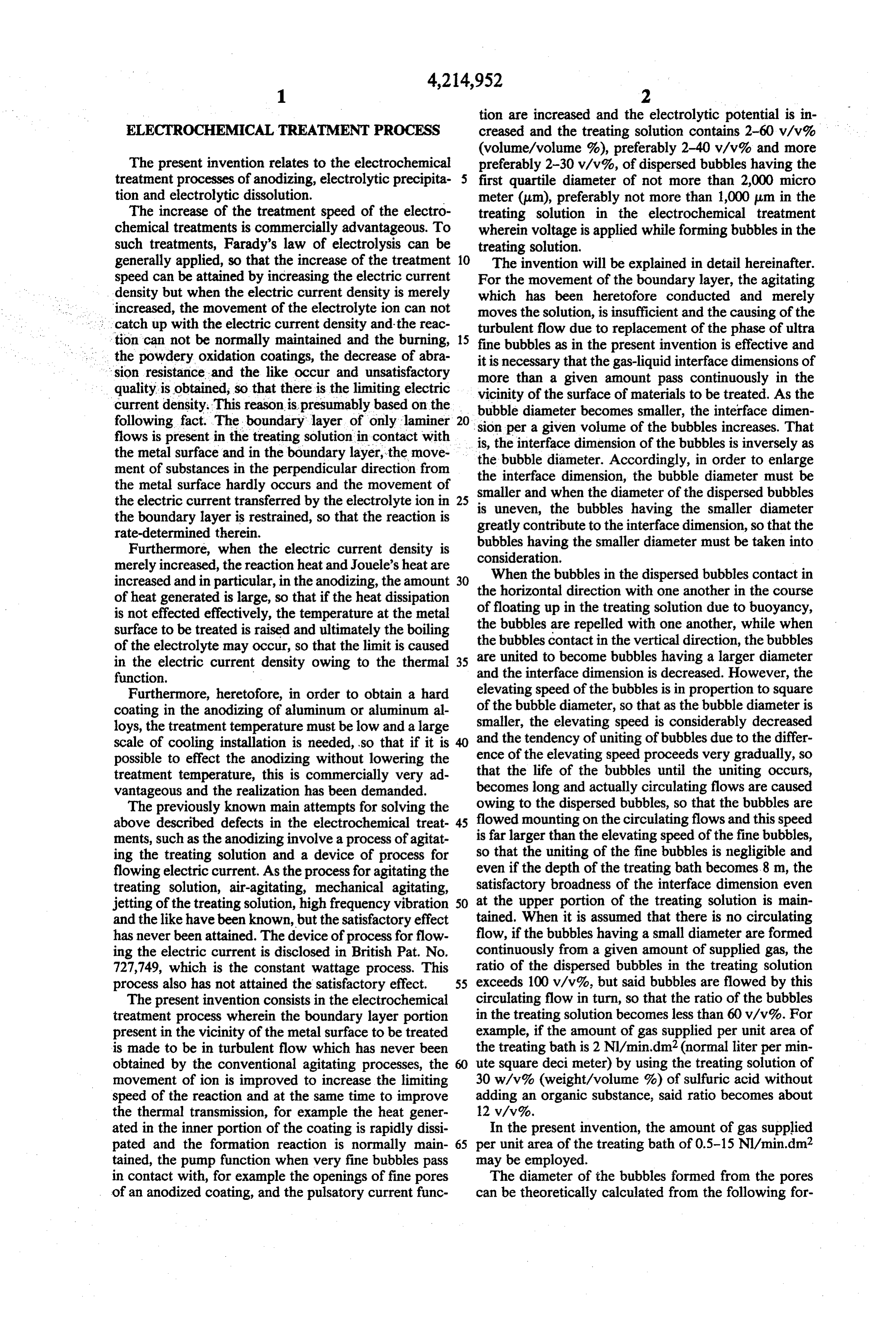
in contact with, for example the openings of fine pores The diameter of the bubbles formed from the pores of an anodized coating, and the pulsatory current func can be theoretically calculated from the following for
Page 7
mula by balance of the buoyancy of the bubbles and the sealed or one of the two plates is replaced with an air surface tension against the porous body. tight plate. Into the inner space of these porous bodies is pumped a gas, such as pressured air.
In the case of porous bodies having an average pore whereing is gravitation constant (cm/sec), p is density 5diameter of somewhat larger than 25 um, rather than pressured air is directly pumped into the porous bodies, (g/cm) of a solution, D is bubble diameter (cm), or is a gas is dissolved in the treating solution under pressure surface tension (dyne/cm) of a solution, d is pore diame and then the treating solution is jetted circularly into an ter (cm) and 6 is angle of contact (degree). electrolytic bath through pores of the porous body and As the process for measuring the bubble diameter, 10 in this case the pressure is reduced and the thus sepa one of two equilateral sides of each of two rectangular rated and formed bubbles are utilized. Such a procedure prisms is oppositely mounted on a horizontal plane is effective in view of obtaining bubbles having smaller respectively at a distance and a light ray from a light diameters and in this case, carbon dioxide gas is more source is incident on one of the prisms at right angles to preferable in view of the solubility to water. said equilateral side through a condenser lense. The 15 The above light ray reflected by the prism is passed through the ranged at the described porous bodies are usually ar bottom portion of the treating bath, but treating solution and then is incident on the other prism. may be arranged together at side portion of the bath or The light ray reflected upward from the latter prism is incident on a camera, which is focused at the bubble in rack. Particularly, when the outer diameter of the cylin the treating solution, so as to take a photograph of the 20 der is made to be small and such cylinders are arranged bubble and the bubble diameter in the taken photograph in multi-stage at the bath bottom zone or a large number is measured. When the thus measured diameter is com of band-shaped porous plates, both surfaces being po pared with the value obtained from the above described rous are arranged in parallel in the thick direction in theoretical formula, it was confirmed that both the such a manner that the breadth direction positions verti values are very similar. cally and the longitudinal direction positions horizon As the means for forming the bubbles in the present 25 tally, whereby the outlets of the bubbles are toward the invention, ceramic or carbonaceous porous body hav horizontal direction, the bubbles are left off and float ing an average pore diameter of 0.5-25 um is used and from the surfaces of the porous bodies at early stage the shape of the porous body, when particularly the owing to the circulating flow of the treating solution, pore diameter is small, is preferred to be cylinder in 30 whereby the bubble diameter can be effectively made view of the strength against air pressure pumped into smaller.
the inner portion of the porous body but a plate-shaped Furthermore, in the cylindrical porous body, a bub porous body may be provided at the whole surface of ble cutting brade may be provided arround said porous the bottom of the treating bath by applying a proper body and the bubbles at the porous body surface are cut reinforcement. Furthermore, plastic sintered porous by said brade rotating arround the porous body. bodies, such as polyethylene, polypropylene, polysty 35 Moreover, the same effect can be obtained by rotat rene, polytetrafluoroethylene and the like may be used. ing the cylyindrical porous body at a revolution speed In addition, porous sintered bodies of acid resistant of 20-500 rp.m. in the electrolyte solution by making metals, such as titanium, niobium, tantalum, zirconium, the cylinder axis as the rotary axis. In this case, precau hafnium, vanadium, stainless steel and the like, or these tion should be taken into the air-tightness of the rotary metal thin plates wherein a large number of pores hav 40 seal portion.
ing about 20 um diameter are perforated in a given The same effect can be obtained by rotating at a revo distance by photoetching may be used. When lead, lution nickel, cobalt or gold thin porous plate wherein a large solutionspeed of up to about 100 rp.m. in the treating the cylindrical porous body by rendering the number of pores having about 20 pum diameter are pro 45 rectangular direction to the cylinder axis as the rotary vided at a distance of 0.5 mm by electroforming in such a state that the inner circumference of the pore projects axis or the plate-shaped porous body by providing the rotary axis at the rectangular direction to the plane of in crateriform of volcano, is arranged at the bottom the plate-shaped porous body. surface of the treating bath or these thin plates are ar The pressured air may be supplied from the outside of ranged in a cylindrical form and bubbles are formed, it 50 the cylindrical porous is possible to obtain smaller bubbles than bubbles trolyte solution flowingbody and dissolved in the elec through the inner space portion formed from the above described porous bodies having of the porous body or mixed in the solution as bubbles the same pore diameter. This is because the circumfer and then introduced into the treating bath. ence of the pore is crateriform, so that the bubbles are more rapidly left off from the pores than the case of 55 terFurthermore, it is effective to make the bubble diame plane and before the bubbles grow to a certain size, the thatformed from the pores of the porous bodies smaller vibration having a frequency of 10-200 Hz is given bubbles are left off from the surface of porous body.
For making the bubble diameter more small, porous to the above described porous bodies. Besides this, it bodies obtained by molding polyethylene, polypropyl disturbs the elevating course of bubbles in the treating ene, polystyrene or polytetrafluoroethylene by using a solution and disperses bubbles throughly in the treating mold produced by electroforming wherein pores solution that the vibration having a frequency of 10-200 project in crateriform of volcano are more effective. Hz is given to materials to be treated or a vibrating plate This is because the porous bodies composed of these is immersed in the treating solution and the vibration materials are larger in the angle of contact of bubbles, so having a frequency of 10-200 Hz is given to the treating that the above described effect is more promoted. solution, so that the bubbles uniformly contact with In the above described porous bodies, in the case of 65 every portion of the materials to be treated and the cylindrical form the end portion is sealed, and in the effect to make the boundary layer portion into turbulent case of plate-form, two plates are arranged at a proper flow due to passing of the ultra fine bubbles through the distance and the distancing portions at the end are surface of the materials to be treated, which is aimed in
Page 8
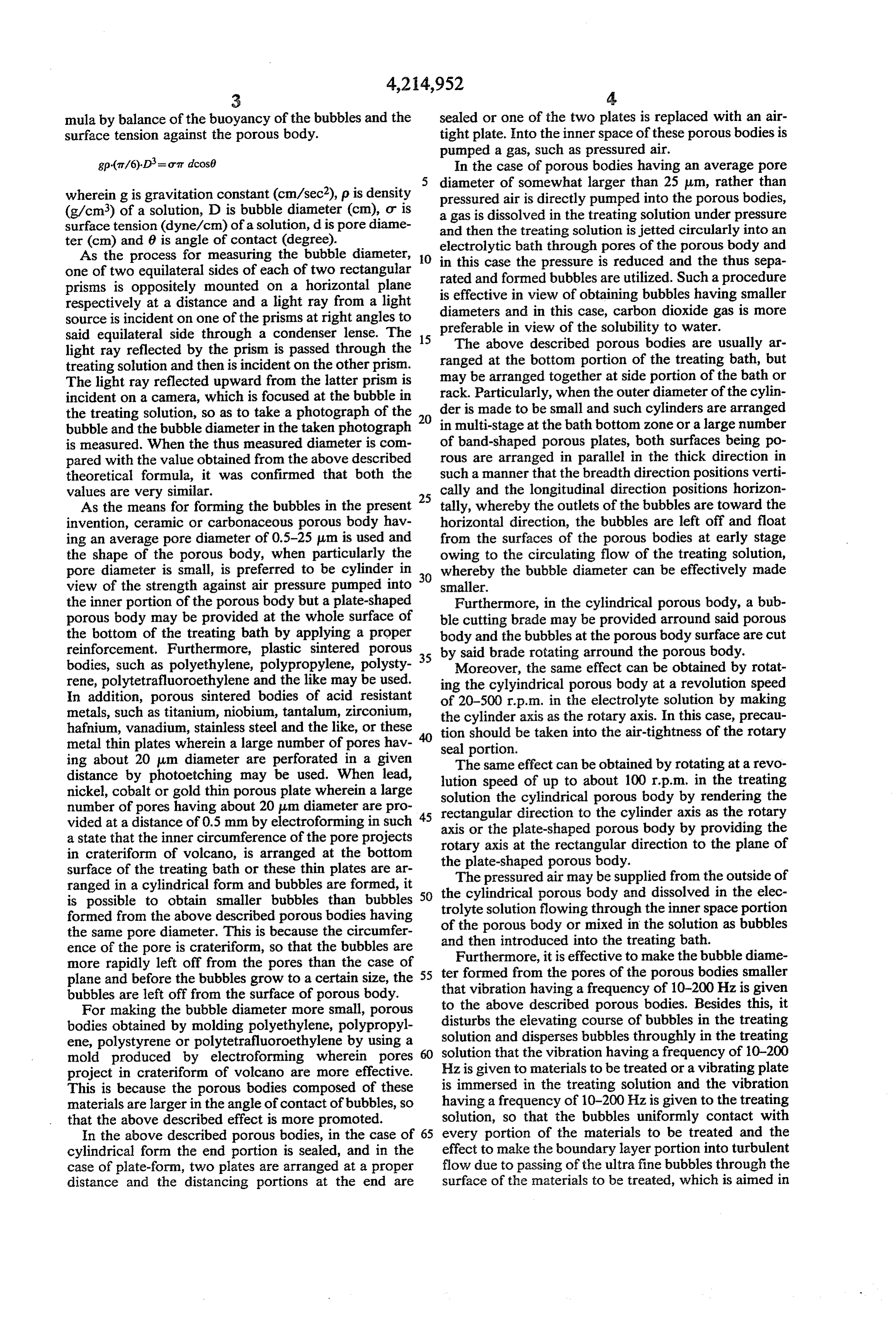
the present invention, is preferably developed. The as described above is substantially negligible, so that it frequency used herein does not give the adverse influ has been found that it is practically advantageous and ence that the vibration energy is converted into the heat further rather convenient from the following reason energy to raise the temperature of the treating solution that the unevenness is permitted in the bubble diameter. as in the ultrasonic wave vibration. 5 That is, when there is difference in the floating velocity The present invention relies upon the above de of every bubble, the bubbles interfer with one another scribed various bubble-forming means and the presence to disturb the floating course and the treatment having of bubbles having a diameter of less than 2,000 um as good uniformity can be effected.
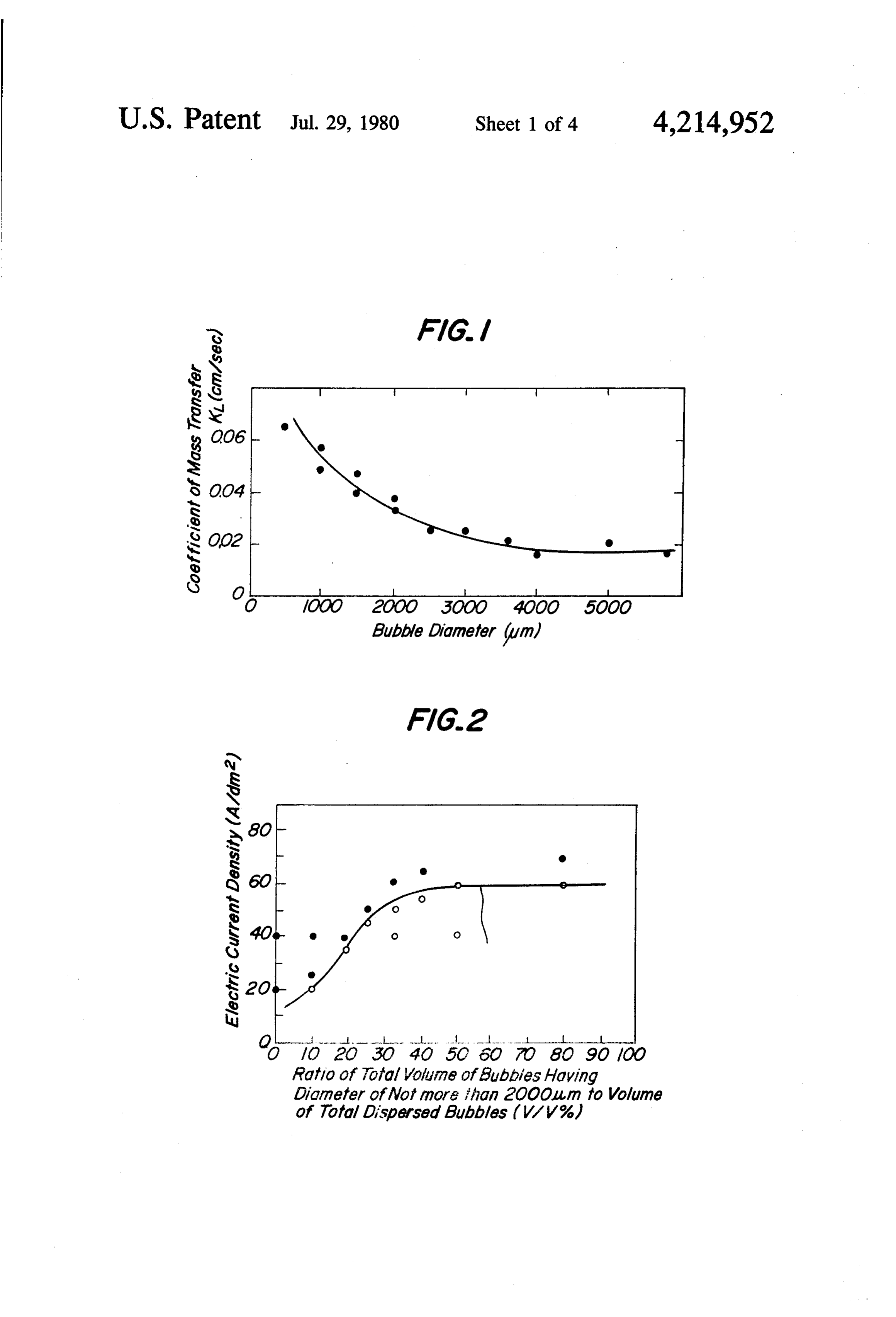
shown in the following Table 1 in the theoretical calcu Then, an experiment has been made by varying the lation or the practical measurement by using the photo O ratio of the total volume of bubbles having diameter of graph process has been confirmed. As the bubbles as not more than 2,000 um to the total volume of all the cend in the treating solution, the pressure due to the dispersed bubbles and as the results, the difference has depth of the solution decreases, so that the volume of been found in the limiting electric current density as the bubble expands and the diameter of the bubble be shown hereinafter. That is, when 30 w/v% of aqueous comes larger but even if the bubbles ascend 8 m of 15 solution of sulfuric acid was used as the treating solu depth; the bubble diameter becomes only 1.22 times as tion, the amount of air supplied per unit area of the bath large as the original bubble diameter. was 2 N/min.dm, the volume ratio of the dispersed Table 1
Average diameter of dispersed bubbles formed from inorganic porous bodies into various treating solutions
Treating Sulfuric acid 30 W/V 9% solution Sulfuric acid 30 W/V 9% Glycerine 20 W/V %
Solution temperature 20 C. 5 C.
Porous body 10 cm above 800 cm above 10 cm above 800 cm above Maximum pore Average pore porous body porous body porous body porous body diameter diameter Porosity Average bubble diameter Average bubble diameter No. (pum) (um) (%) (um) (pum)
5 12 O 45 870 1,310 1,040 1,600
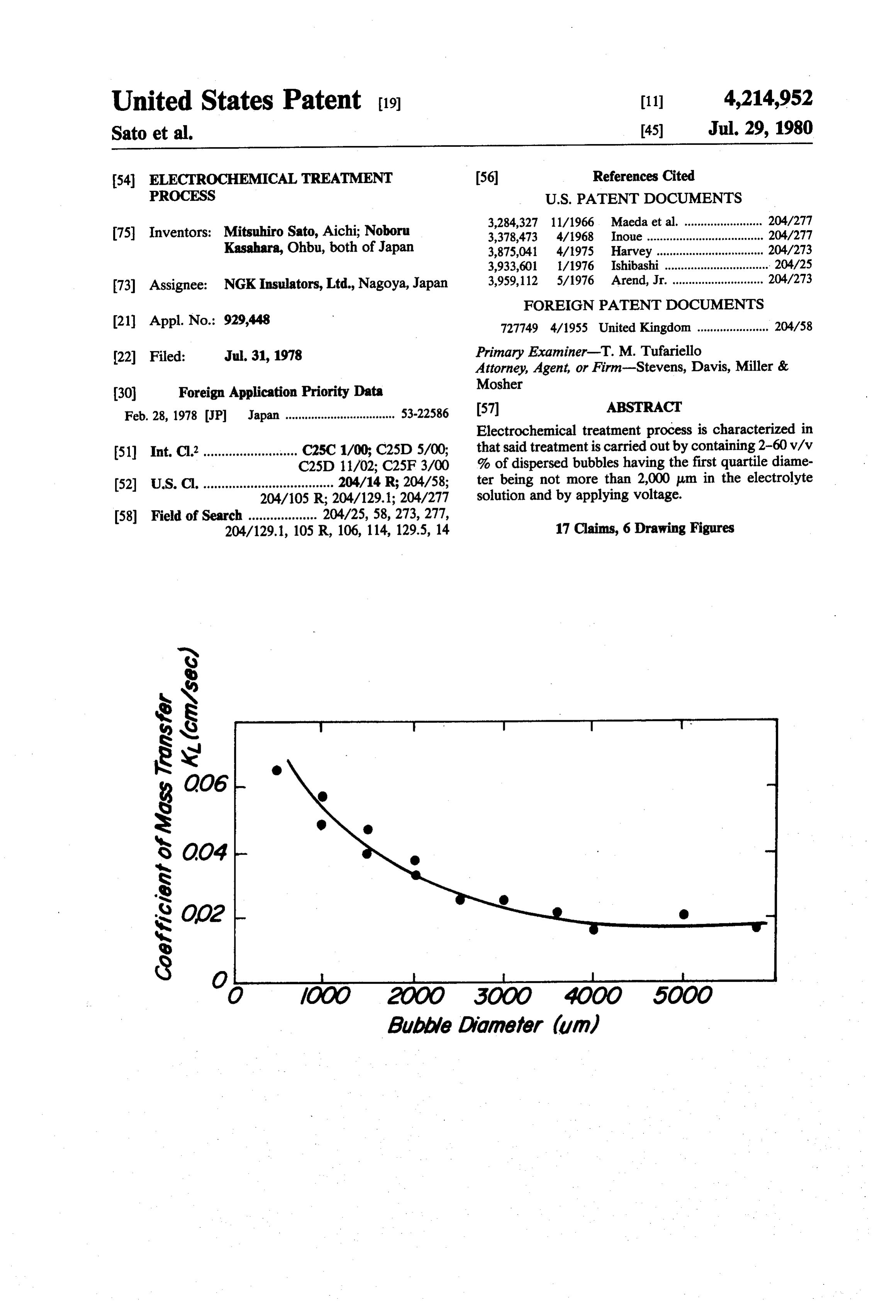
When the coefficient of mass transfer KL (cm/sec) 35 when the bubble diameter is varied in single bubble was measured by absorption of carbon dioxide gas into wa bubbles in the treating solution was 12.2%, anodizing ter, the results as shown in FIG. 1 were obtained. As was carried out at various electric current densities and seen from FIG. 1, the coefficient of mass transfer gradu the limiting electric current density was determined, the ally increases at not more than 4,000 um of the bubble 40 results as shown in FIG. 2 were obtained. In FIG. 2, the diameter and suddenly increases from not more than blackpoints show when the appearance of the coating is 2,000 um of the bubble diameter and becomes maximum burnt and the coating is bad and the white circles show at not more than 1,000 um of the bubble diameter. Since the sound coating. This shows that is the ratio of the the coefficient of mass transfer corelates to the heat total volume of the bubbles having diameter of not more transmission, this shows that the use of the bubbles 45 than 2,000 pm to the total volume of the dispersed having diameter of not more than 2,000 um, particu bubbles is not more than 25%, the bubbles which have larly not more than 1,000 um is advantageous. the function capable attaining the effect of the present Thus, the bubbles having the smaller diameter are invention are few and the limiting electric current den more valuable. When the diameter of every bubble in sity lowers. Accordingly, it has been found that it is the dispersed bubbles is uniform, it seems that the float 50 necessary in order to obtain the effect aimed in the ing velocity of every bubble becomes equal and the present invention to effect the treatment by making the uniting of bubbles does not occur and the dispersability ratio more than 25%. In the same manner, an experi becomes stable and such a case is preferable, but the ment has been made by varying the ratio of the total relative speed of every bubble in the circulating flow to volume of the bubbles having diameter of not more than the treating solution in this case becomes only the static 55 1,000 um to the total volume of the dispersed bubbles float velocity of each bubble and every bubble floats up and the same tendency as in the above described case of softly at the equal disposal without interferring with the diameter of not more than 2,000 um has been ob one another and the disturbance is few. Thus, the mix tained. It is practically feasible to carry out the treat ing in the treating solution becomes few, so that even if ment by making the ratio more than 25% and this means the bubble diameter is made to be uniform, the effect 60 that when the first quartile diameter is not more than proportional to the uniformity can not be expected and 2,000 m, preferably not more than 1,000 um, the above it is practically difficult to make the bubble diameter described limiting electric current density is increased. uniform, accordingly in the present invention the im Furthermore, it is necessary that the interface area of provement in the state where there is unevenness in the the bubbles is more than a given limit and this can be bubble diameter, has been attempted. 65 attained by making the ratio of the bubbles in the treat At the bubble diameter of about 2,000 um, even if ing solution to be more than 2 v/v%. When said ratio there is a certain degree of unevenness in the bubble exceeds 60 v/v%, as the ratio increases, the circulating diameter, the disadvantage due to the uniting of bubbles flow becomes fast and the bubbles are rapidly carried
Page 9
off to the surface of the treating solution and the bubbles tance than the coatings obtained by the conventional are broken and disappear at the solution surface and a technics and these excellent properties can be obtained large amount of air supplied is needed. If a large amount in a higher speed.
of bubble stabilizer is used, the disappearance of the The anodizing according to the present invention can bubbles is not satisfactorily effected and a bubble layer be applied to powder sintered bodies composed of alu grows and the effect to the boundary layer is not so minum or aluminum alloys. The formed coatings ob much increased, so that the ratio is sufficient in a value tained by applying the anodizing according to the pres of up to 60 v/v%. The ratio of 2-40 v/v% is preferable ent invention to said powder sintered bodies, when the and 2-30 v?v% is more preferable. sintered bodies are porous, are formed to a fairly deep As the treating solution to be used when the present 10 portion through the opened pores and the adhesion and invention is applied to the anodizing, mention may be hardness are satisfactory and when the porous sintered made of sulfuric acid, oxalic acid, phosphoric acid, bodies treated with the method of the present invention benzenesulfonic acid, sulfanic acid, boric acid, ammo are used in oil lubrication, the lubricating oil is apt to be nium borate, citric acid, tartaric acid, formic acid, suc held in the opened pores and further the coatings are cinic acid and/or chromic acid. The temperature of the 15 high in the abrasion resistance, so that the obtained treating solution is usually from 0° C. to room tempera products show good abrasion resistance. ture but the treatment may be effected at a temperature Similarly, the present invention can be applied to from room temperature to 100° C. depending upon the powder sintered bodies, castings, electrolytic precipi kind of the treating solution. That is, when sulfuric acid, tated products, hot sprayed products obtained by dis oxalic acid, phosphoric acid, benzenesulfonic acid and 20 persing abrasion resistant and antifrictional particles, Mor sulfamic acid, which are most usually used, the such as alumina, silicon carbide, asbestos, molybdennan treatment is carried out at a room temperature or a disulfide, carbon and the like in aluminum or aluminum temperature of lower than room temperature. When alloys, and ones obtained by infiltrating aluminum or acids having a dissociation constant of less than aluminum alloys in opened pores of porous bodies com 1X 10⁻³ at 25 C., such as boric acid, ammonium borate, 25 posed of abrasion resistant and antifrictional particles, ammonium carbonate, citric acid, succinic acid, tartaric such as alumina, silicon carbide, asbestos, molybdenum acid and/or formic acid are used, the treatment may be disulfide. That is, since the particles to be used herein effected at a temperature from room temperature to are inactive to the treating solution, the formation reac 100° C. This range of temperature has the merit that a tion of aluminum or aluminum alloy portion is feasible. large size of cooling installation for holding the treating 30 Other than the above described aluminum or alumi solution at a temperature of 0° C. or lower which has num alloys, the present invention can be applied to been heretofore desired for forming an anodized hard beryllium, beryllium alloys, magnesium, magnesium coating, is not necessary. alloys, titanium, titanium alloys, niobium, niobium al The electric current density to be used in the present loys, tantalun, tantalum alloys, zirconium, zirconiu in invention is usually 3 A/dm2 to 60 A/dm2 under the 35 alloys, hafnium, hafnium alloys, vanadium, vanadium above described temperature condition and even 80 alloys, tungsten, tugsten alloys, molybdenun, molybde A/dm2 may be used by decreasing the treatment tem num alloys, lead, lead alloys and the like, and composite perature. In particular, when the process of the present materials, such as powder sintered bodies, castings, invention is applied while running aluminum wire or electrolytic precipitated products, hot sprayed products strip at a large relative velocity to the treating solution, and infiltrated products composed of metals in which the electric current density of about 170 A/dm2 may be the dissolution is not substantially effected on ancidiz used, the "powdery coating oxidation' and "burning' ing, such as alloys of combination of these metals. In phenomena of the coating heretofore formed under particular, the products obtained by treating the com such temperature condition and electric current density posite material of lead with the method of the present can be prevented by containing the total volume of the 45 invention are good in the heat dissipation and excellent above described bubbles having a diameter of not more in the abrasion resistance against rubbing even under than 2,000 um in an amount of more than 25% based on high load and high speed.
the total amount of the dispersed bubbles, that is render Furthermore, in titanium, noibium and tantalum, ing the first quartile diameter to be not more than 2,000 withstand voltage and dielectric constant are increased um and further rendering the ratio of the bubbles in the 50 and these products are useful as condenser. treating solution to be 2-60 v/v%, whereby the func As the materials to be treated, ones obtained by coat tion of the ion acting the formation is increased and the ing surfaces of the materials with aluminum by means of heat generated in the inner portion of the coating is dry plating, electrolytic plating by means of non-aque effectively dissipated, and further the dense coating can ous solution, hot spraying or dipping may be used and be obtained at a high speed. 55 the thus obtained materials are subjected to anodizing The anodizing among the present invention can be by the method of the present invention. In particular, applied to all the practically used aluminum and alumi when aluminum is melt coated on steels and the aiurai num alloys. In particular, the present invention can be num coated steeis are treated with the nethod of the applied to a cast aluminum alloy containing about 20% present invention to form anodized coating, the heat of silicon which has been heretofore difficult in the 60 resistance and the resistance to hot soil adherence are formation of coating. Furthermore, to high strength improved.
cast aluminum alloy containing 12% of copper and Similarly, the present invention can be applied to highly strong and heat resistant aluminum alloy con powder moldings, powder sintered bodies, coatings, taining 2% of nickel, 4% of copper and 1% of silicon, injection moldings, hot sprayed products and infiltrated good coatings can be formed. The coatings obtained by 65 products composed of aluminum or aluminum alloys, treating these materials with the method of the present and antifictional plastics, such as polyethylene, poly invention are equal or higher in the adhesion, hardness, propylene, polyamides, polyacetal, polytetrafluoroeti abrasion resistance, heat insulation and corrosion resis ylene. In the composite materials of these antifrictional
Page 10
plastics, the products obtained by treating with the ponent of the treating solution and oxalic acid and the method of the present invention are light weight and other organic acids are better in the stability of the rich in the abrasion resistance and many products can be dispersed bubbles than sulfuric acid and the bubble used in non-feeding oil. diameter in the vicinity of the material to be treated is When the above described powder sintered bodies smaller.
composed of aluminum or aluminum alloys or the above The above explanation was mainly made with respect described composite materials are subjected to the an to the anodizing of aluminum or aluminum alloys but odizing according to the present invention and then the the treatment of the present invention can be applied to obtained materials are subjected to infiltration or elec electrolytic machinings, such as general electro-plating, trolytic precipitation by using lead, tin or the alloy of 10 alloy electroplating, electroforming, electrolytic refin these metals, the obtained products are more improved ing of metals, sodium electrolysis, electrolytic precipita in the abrasion resistance than ones obtained by treating tion of secondary battery, electrolytic polishing, elec the previously formed composite materials with the trolytic cutting and the like and in these applications, anodizing according to the present invention and can be the turbulent flow at the boundary layer portion, which used under high loads without supplying oil. 15 rate-determines the reaction, also occurs in the same If the anodizing according to the present invention is manner as in the anodizing, so that the surprising com used, the mechanical application can be broadened by mercially advantageous effect as compared with the utilizing the high hardness, and further since the elec conventional process can be brought about as men trolytic voltage can be increased, the barrier layer of the tioned above. That is, the increase of the limiting elec coating can be increased and the dielectric strength is 20 tric current density, the improvement of throwing increased, so that the electric property is also improved. power, the improvement of current efficiency, the ex In the application wherein the coating is used as the pansion of bright electric current density range, the electric insulating layer, if the dielectric strength is decrease of electrolytic resistance, the uniformity of increased by thickening only the barrier layer, the elec composition in alloy electroplating and the uniform trostatic capacity between the base of aluminum and the 25 dispersibility in the compound electroplating are very barrier layer is not negligible and such a coating may advantageous effects in the electrolytic precipitation not be used for a circuit substrate because of presence of industry.
the floating electrostatic capacity. For solving this The introduction of bubbles into the electroplating problem, the method according to the present invention solution has been heretofore carried out but in this can be applied. In the condition for forming the porous 30 means, bores having a diameter of 1-3 mm are per type coating, according to the method of the present porated at chemicals resistant pipes, such as vinyl chlo invention the thick coating can be easily formed, so that ride and bubbles having a diameter of about 4 mm are even if a conductive ciruit is provided on the coating formed and this is merely agitating of the solution and surface, the distance between the aluminum base and the effect of the treatment process of the present inven the circuit through the coating can be enlarged and the 35 tion can not be attained. The above described effects electrostatic capacity is negligible and at the same time can be obtained only by passing the above described the barrier layer can be thickened and the dielectric fine bubbles as in the present invention in the vicinity of strength can be satisfied. the surface of the materials to be treated with the inter This is further developed and a material to be treated face dimension of more than a given amount. in which a thick coating has been formed under the In the electroplating, the precipitated coating is me condition for forming a porous layer type coating, may tallic and has good conductivity and also in the com be further transferred into the treating solution to form pound electroplating, a metallic substance of more than the barrier type layer and treated while further increas about 70 w/w% is contained and the conductivity is ing the electrolytic voltage. high, so that the heat amount generated in the inner In the anodizing according to the present invention, 45 portion of the coating at the electroplating is small. This the decrease of solid-liquid interface tension of the treat is different in the function from the dissipation of heat ing solution enlarges the contact angle of bubbles generated in the inner portion of the coating in the against the porous body and is effective for making the anodizing of aluminum or aluminum alloys but in the pore diameter smaller from the theoretical formula of electroplating, it is important to increase the homogeni the diameter of the bubbles formed from the pores and 50 zation of the electrolyte, to lower the concentration a surface active agent stable to an electrolyte can be gradient and to increase the limiting electric current selected and added to the treating solution. As this one density and the effect when the present invention is embodiment, glycerine of less than 15 w/v% may be applied to the electroplating depends greatly upon the used. The increase of the viscosity of the treating solu substantial homogenization of the electrolyte and the tion and the use of an interface adsorbing substance of 55 conventional various agitating processes only agitate bubble make the dispersed bubbles formed from the the treating solution at a distance from the surface of the porous body stable and restrain the tendency that the materials to be electroplated and the above described bubbles are united to form the bubbles having a larger effects have not been obtained. Since Faraday's law of diameter and restrain the decrease of the interface di electrolysis is well applied to the electroplating, the mension of the bubbles, so that such procedures are increase of the limiting electric current directly be convenient. As an embodiment of this object, saponin, comes increase of the electroplating speed and in the such as hederin (C4H6O12), crystal violet case of electroplating according to the present inven (C25H30ClN3), higher alcohols, such as butyl alcohol, tion, the coating speed is increased to about more than glycols, such as ethylene glycol, arabit (C5H12O5), glyc 2 times as fast as the conventional electroplating and erine and the like may be added. In particular, the 65 various properties, such as the uniformity of coating higher alcohols have the debubbling ability, so that the and the throwing power are improved. use of said alcohols is advantageous in handling. Fur When the present invention is applied to the electro thermore, the stability varies depending upon the com lytic polishing, it has been confirmed by a bright meter
Page 11
that the polishing brightness is improved. This is be abrasion resistance being more than 8g of carborundum cause the ultra fine bubbles promote the polishing func per um of the coating thickness is checked from FIG. 4, tion and the electric current density distribution be even 20 A/dm2 of the electric current density can be comes uniform. When the bubbles which have been operated at 2,000 um of the first quartile diameter and at used in the conventional technic are introduced into 1,000 um of the first quartile diameter about 30 A/dm2 electrolytic polishing, the flow speed of the polishing of the electric current density can be operated. solution becomes ununiform due to the large bubble FIG. 5 shows that Vicker's hardness of more than 350 diameter and flow patterns are formed on the polished can be obtained at the anodizing speed of more than 4 surface and such a process has not been satisfied. um/min at the first quartile diameter of not more than When the present invention is applied to the electro 10 2,000 um. Even in the conventional best technic, the lytic cutting, the fine bubbles act to effectively carry out highest anodizing speed of the coating thickness satisfy the electrolytic products and the cutting speed can be ing more than 350 of Vicker's hardness does not exceed increased and the cut surface is smooth and fine. 2 um/min. Accordingly, the anodizing speed of the The invention will be explained in more detail. present invention exceeds two times as fast as the con For a better understanding of the invention, reference 15 ventional technic. In this example, the ratio of the dis is taken to the accompanying drawings, wherein: persed bubbles in the treating solution is b 15-1 v/v%. FIG. 1 is a graph showing the relation of the coeffici EXAMPLE 2 ent of mass transfer to the bubble diameter;
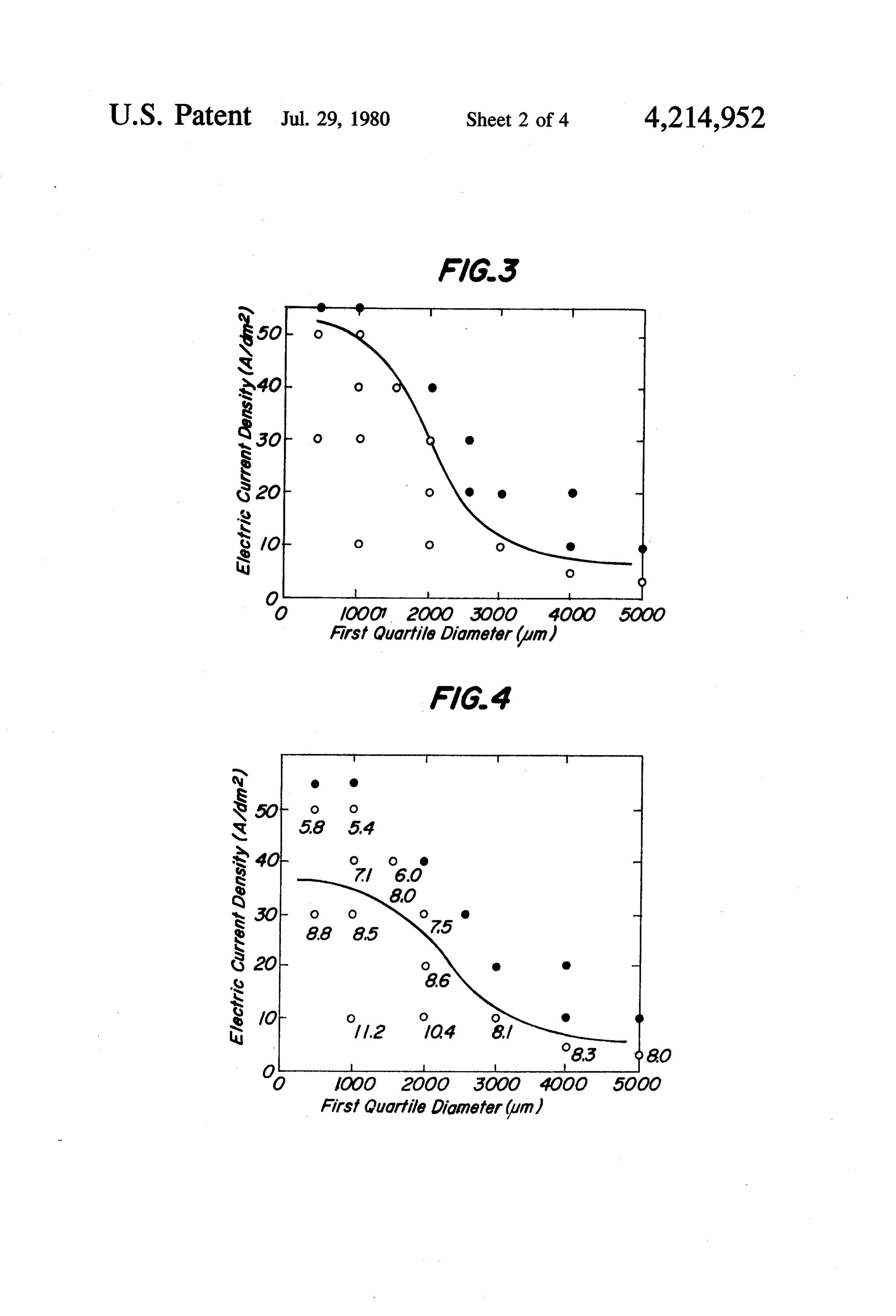
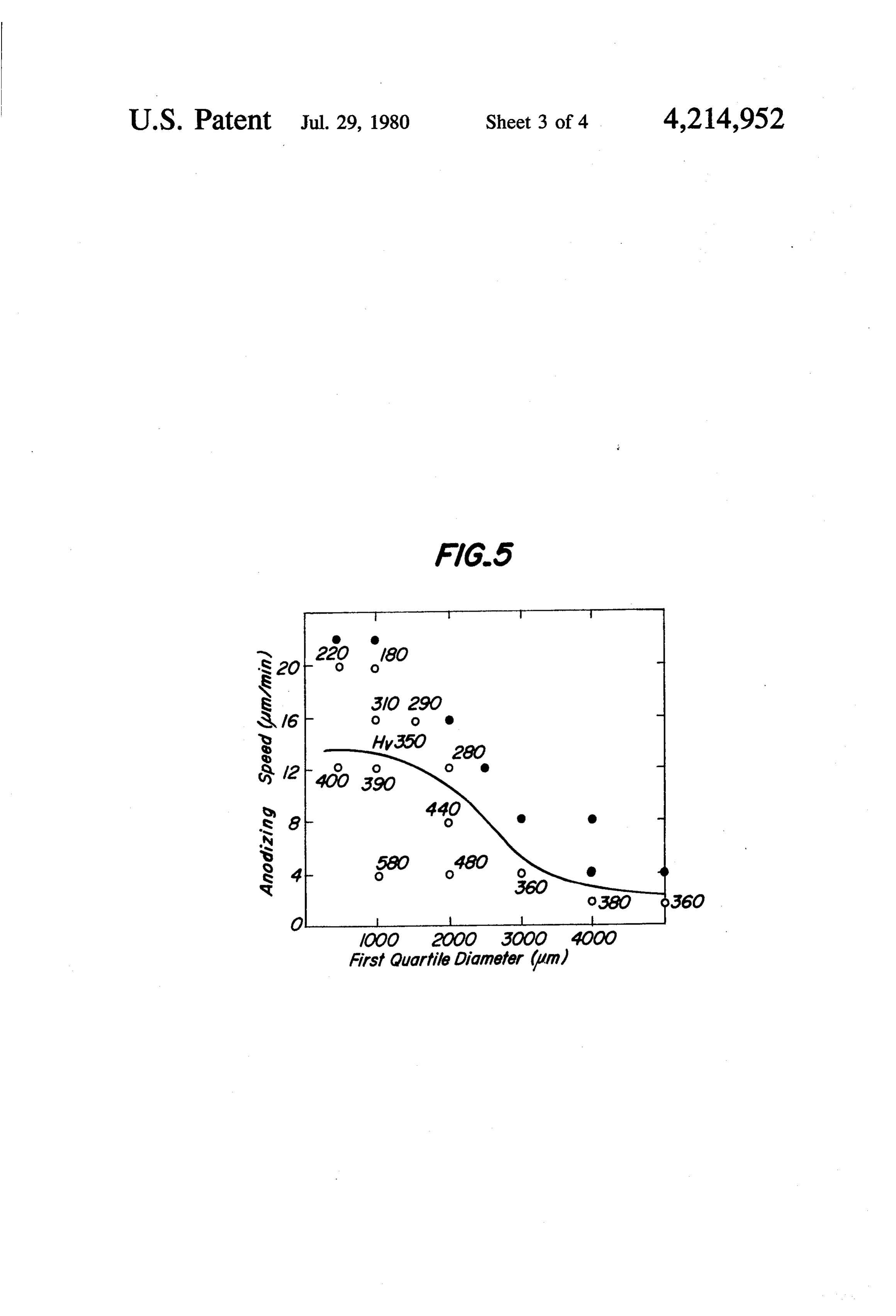
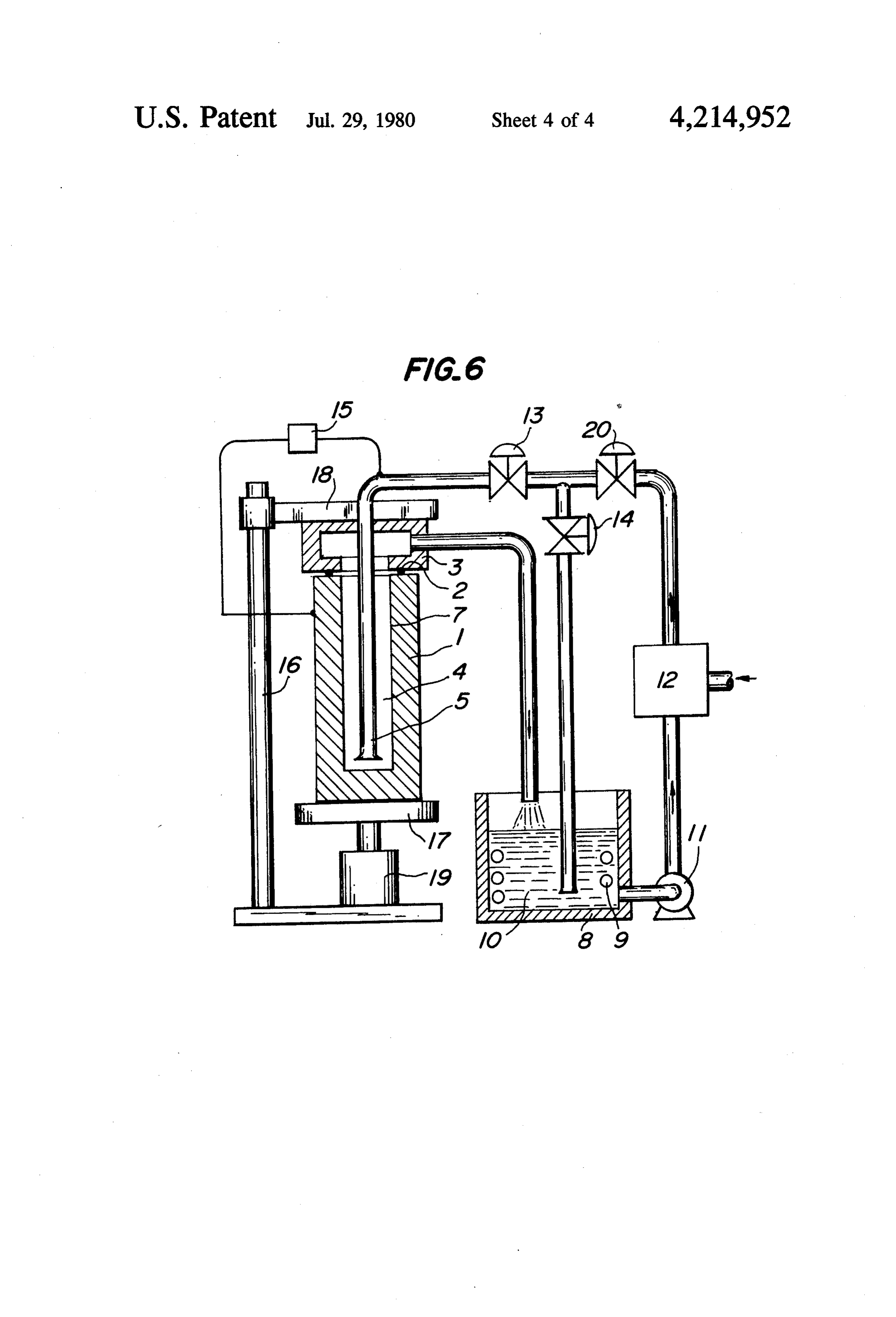
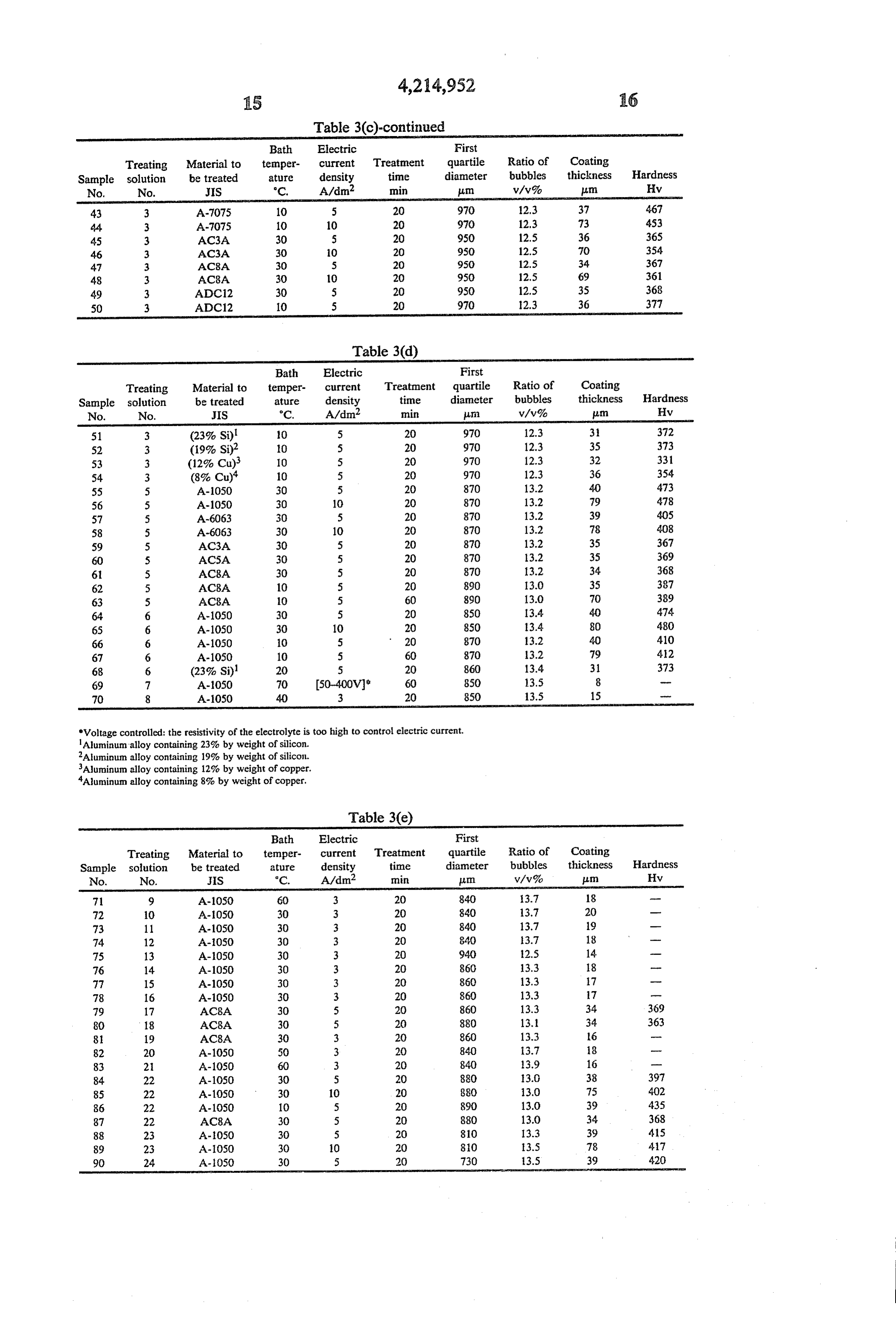
FIG. 2 is a graph showing the appearance distribution Anodizings were carried out by using various aque when the ratio of the total volume of the bubbles having 20 ous solutions having the compositions of the treating a diameter of not more than 2,000 um to the volume of solution Nos. 1-24 as shown in Table 2 and varying the the total dispersed bubbles and the electric current den materials to be treated, the bath temperature, the elec sity are varied; tric current density and the treatment time. At the treat FIG. 3 is a graph showing the appearance distribution ment condition, the first quartile diameter of the dis when the first quartile diameter and the electric current 25 persed bubbles in the vicinity of the material to be density are varied; treated and the ratio (v/v%) of the total dispersed bub FIG. 4 is a graph showing the distribution of gram bles in the treating solution were measured and after the weight of carborundum per the coating thickness of the treatment, the thickness of the anodized coatings abrasion resistance test when the first quartile diameter formed on the surface of the materials to be treated was and the electric current density are varied; 30 measured by an eddy-current instrument for measuring FIG. 5 is a graph showing the hardness distribution thickness and the hardness was measured by Vicker's against the first quartile diameter and the anodizing hardness meter. These treatment conditions and the speed, and results of the above described various measurements are FIG. 6 is a diagram for explaining an apparatus for shown in the following Tables 3.
anodizing only the inner surface of the cavity provided 35 As the cathode in this case, use was made of carbon with bottom of the material to be treated and having the plates and as the supplied gas, use was made of air at cavity provided with bottom, for example the inner room temperature and the dimension of the surface of cavity portion. the treating solution was 500 mmX400 mm and the The following examples are given or the purpose of depth of the solution to the porous body was about 500 illustration of this invention and are not intended as 40 limitations thereof.
Table 20a)
Anodizings were carried out by using 20 w/v% of solution Composition aqueous solution of sulfuric acid as the anodizing solu 45 2 H2SO4 Swww2. tion, maintaining the bath temperature at 28-E2 C., 3 H2SO4 30 wave using aluminum having a usual purity of JIS-A1050 as a 4. H2SO4 50 ww.9% material to be treated, using various porous bodies to 5 (COOH)2.2H2O 4 ww2. form bubbles and varying the electric current density 6 (COOH)2.2H2O 20 wav% variously with a constant electric current density pro 50 7 H3BO3 10 ww?
cess. The anodizing intended to obtain about 50 pum of 9 CH(OH)COOH)2 Swww2. coating thickness and the diameter of the formed bub 10 CH3CH(OH)COOH 5 www% bles was measured by the above described photograph process and the results were shown in a diagram as the cumulative distribution of the bubble diameter to deter 55 Table 20b) mine the first quartile diameter. The obtained results are Treating shown in FIG. 3, the blackpoint shows burning and bad solution Composition products and the white circle shows the sound condi 11 CH4OH) (COOH)3. H2O 5 w/v2 tion. 12 (CH2COOH)2 5 wav% The results of the abrasion resistance test in this case 60 13 H3PO4 10 www2. is shown in FIG. 4 and the hardness of the same samples 14 C6H5SO3H .2H2O 5 w/v2. is shown in FIG. 5 wherein the ordinate shows the 15 (NH4)2B4O7 S w/v2
anodizing speed. The numeral values in FIG. 4 show H2SO4 10 w/v.2% the weight (gram) of carborundum per micro meter 17 (COOH)2.2H2O
(um) of the coating thickness. The numeral values in 65 18 (COOH)2.2H2O 1 wav% FIG. 5 show Vicker's hardness. The amount of air sup H2SO4 1 wav% plied in this case was 2 N/min.dm2 per the significant 19 (COOH)2.2H2O 10 wav2. bath surface dimension. When the zone of the high H3BO3 10 ww2.
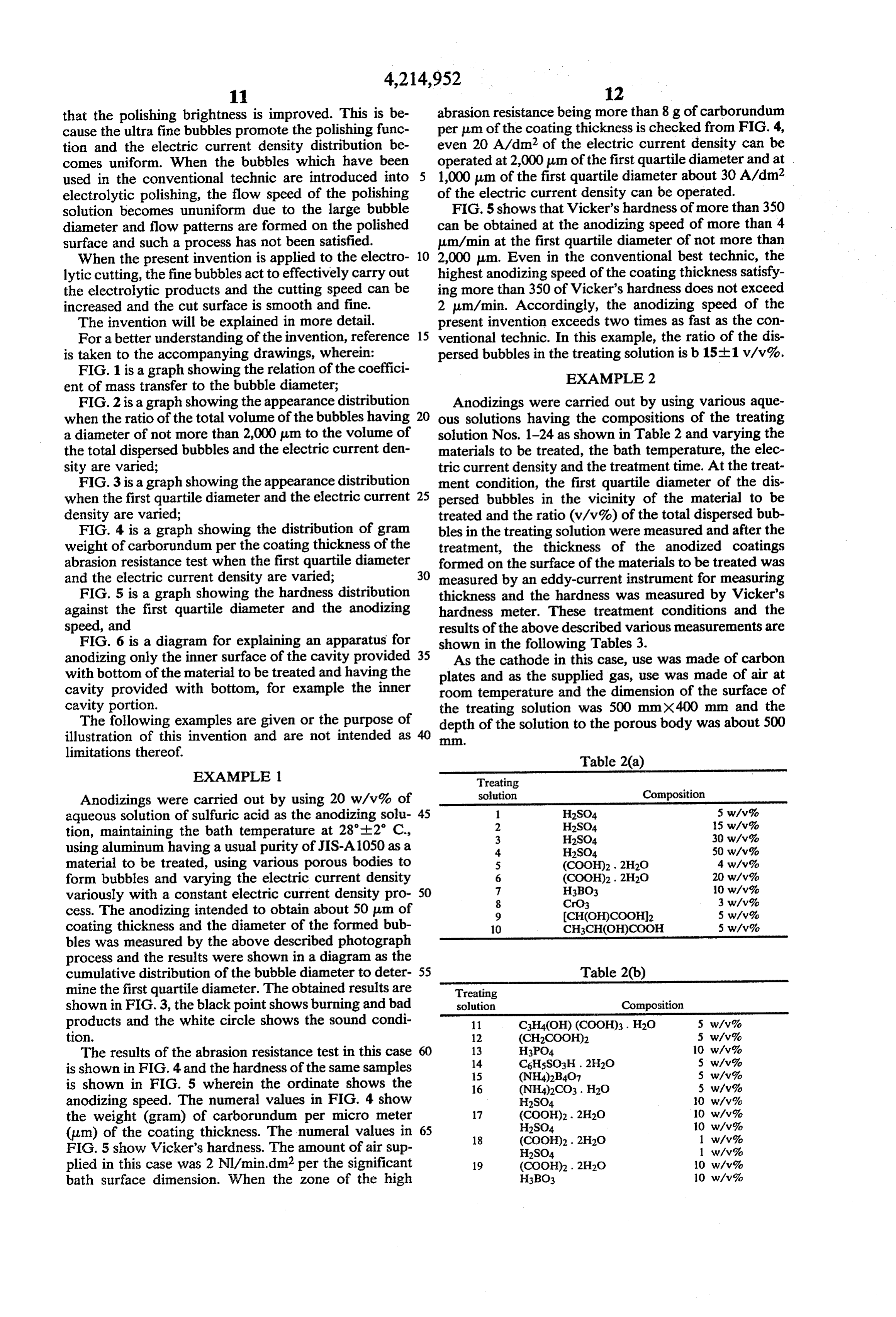
Page 12
Table 20b)-continued. .. . . Table 20b)-continued Treating . ... Treating solution Composition . ... solution Composition 20 CH4OH) (COOH)3. H2O S w/v% 22 C3H5(OH)3 3 w/v.2% TiO(KC2O4)2.2H2O 40 g . ... H2SO4 30 ww.9% HBO3 8g 23 C3H5 (OH)3 30 w/v.9% 21 C3H4OH) (COOH)3. H2O 1 g ... H2SO4 . . . . 1 w/v% (COOH)2.2H2O 1.2 g 24 (COOH)2.2H2O. 10 w/v2 H2O 1 CH5 (OH) ' ' . 10 w/v% H2SO4 30 w/v% i. ... . . . .
Table 3(a)
Bath First Electric .
Treating Material to temper- current Treatment quartile Ratio of Coating:
Sample solution be treated ature density time diameter bubbles thickness Hardness . No. No. JIS C. A/dm? min plm v/v% um Hv 2 A-050 20 1 30 - 0. 7.5 - . Conven- 2 A-1050 20 2.5 30 - 0. (Burning) tional process 2 A-1050 5 2.5 60 -- 0 38 400 2 A-1050 s 3 60 - O (Burning) -- 3 A-1050 30 1.5 20 --- O (Powdery) 1 3 A-1050 30 5 20 270 6.7 42 472 2 3 A-1050 30 5 60 310 4.8 121 470 3 3 A-1050 30 5 20 440 14.2 41 462 4. 3 A-1050 30 5 60 440 4.2 120 459 5 3 A-1050 30 5 20 640 13.3 40 457 6 3 A-1050 30 5 20 710 13.1 40 455 7 3 A-1050 30 5 60 710 13.1 118 450 8 3 A-050 30 5 20 950 12.5 40 400 9 3 A-1050 30 5 60 950 12.5 115 396 10 3 A-1050 30 5 20 1050 11.6 39 366 11 3 A-1050 30 5 20 420 19.4 38 198 12 3 A-1050 30 3 20 2000 17.3 22 202
Table 3(b)
Treating Material to temper- current Treatment quartile Ratio of Coating Sample solution be treated ature density time diameter bubbles thickness Hardness No. No, JS °C. A/dm min um w/v% Am Hv 13 3 A-1050 30 10 20 950 12.5 76 453 14 3 A-1050 30 30 20 70 13.1 114 390 15 3 A-1050 30 50 20 730 8.1 152 180 16 3 A-1050 10 5 20 970 12.3 40 512 17 3 A-1050 10 30 20 970 12.3 77 420 8 3 A-1050 10 50 20 970 12.3 115 330 19 3 A-1050 10 70 20 730 12.7 154 210 20 3 A-1050 30 5 20 940 3.5 39 247 21 3 A-050 30 5 20 990 32.6 38 251 22 3 A-1050 30 5 20 1030 43.3 37 190 23 3 A-1050 30 3 20 1380 55.0 21 160 24 3 A-1050 40 5 20 930 12.7 38 312 25 3 A-1050 5 5 20 980 12.0 41 554 26 4. A-1050 30 5 20 1250 10.7 40 340 27 2 A-1050 30 5 20 910 13.0 39 414 28 2 A-1050 10 5 20 930 12.6 40 527 29 A-1050 30 5 20 900 13.2 40 412 30 1 A-1050 O 5 20 920 12.8 41 520
Table 3(c)
Treating Material to temper- current Treatment quartile Ratio of Coating Sample solution be treated ature density time diameter bubbles thickness Hardness No. No. JIS °C. A/dm? min m v/v% m Hv S1 3 A-5052 40 5 20 930 12.7 34 332 32 3 A-5052 30 5 20 950 12.5 38 397 33 3 A-5052 30 O 20 950 12.5 75 395 34 3 A-5052 20 5 20 960 12.4 39 401 35 3 A-5052 10 5 20 970 12.3 39 434 36 3 A-2017 30 5 20 950 2.5 35 398 37 3 A-207 30 5 60 950 12.5 02 386 38 3 A-6063 30 5 20 950 12.5 40 402 39 3 A-6063 30 5 60 950 12.5 118 397 40 3 A-6063 30 8 20 950 12.5 64 42 41 3 A-7075 30 5 20 950 12.5 36 400 42 3 A-7075 30 5 60 950 12.5 106 387
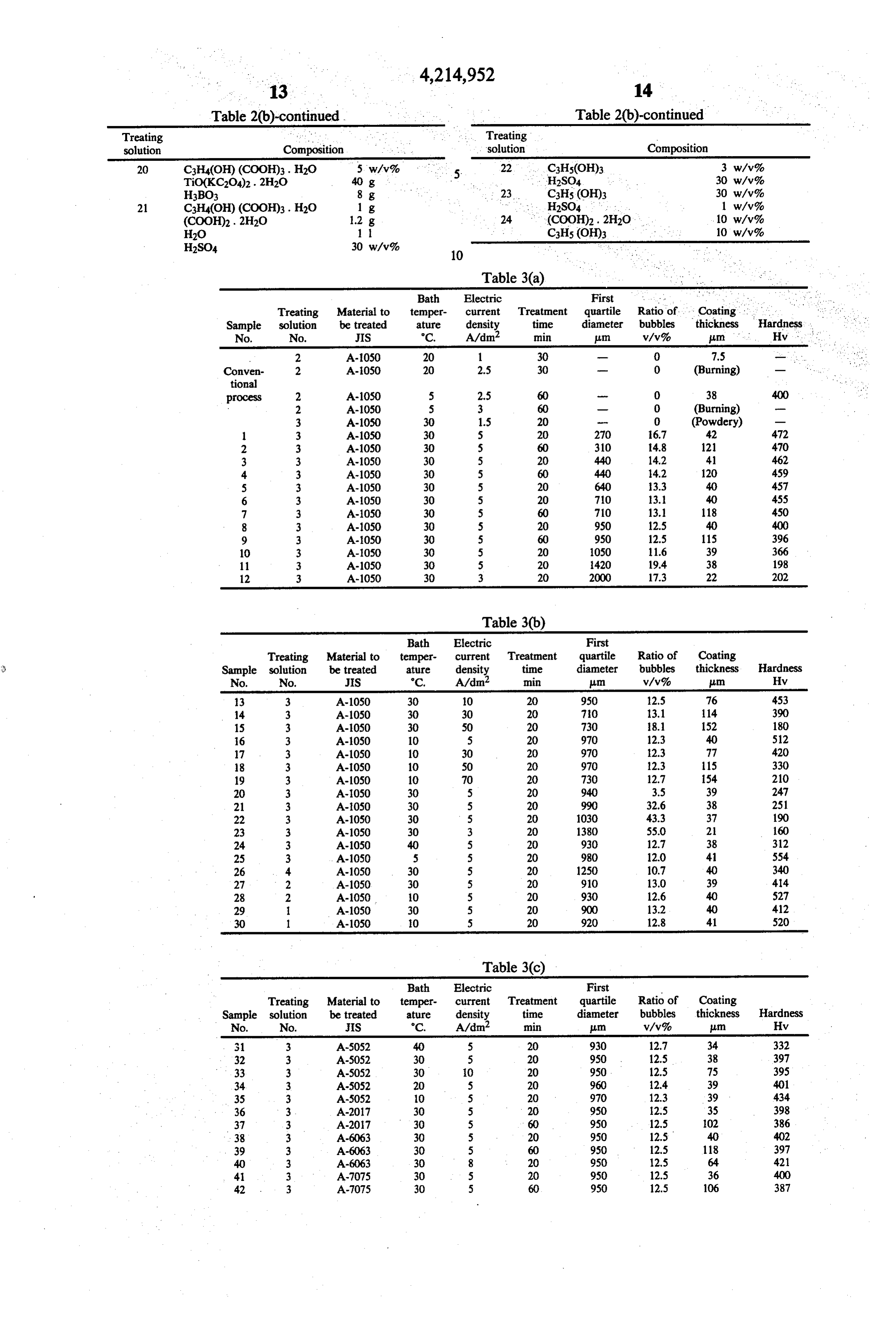
Page 13
Table 3(c)-continued
Treating Material to temper- current Treatment quartile Ratio of Coating Sample solution be treated ature density time diameter bubbles thickness Hardness No. No. JIS °C. A/dm? min pum v/v% im Hv 43 3 A-7075 10 5 20 970 12.3 37 4.67 44 3 A-7075 10 10 20 970 12.3 73 453 45 3. AC3A 30 5 20 950 12.5 36 365 46 3 AC3A 30 10 20 950 12.5 70 354 47 3 AC8A 30 s 2O 950 12.5 34 367 48 3 AC8A 30 10 20 950 12.5 69 361 49 3 ADC12 30 5 20 950 12.5 35 368 50 3 ADC12 10 5 20 970 2.3 36 377
Table 3(d)
Treating Material to temper- current Treatment quartile Ratio of Coating Sample solution be treated ature density time diameter bubbles thickness Hardness No. No. JIS °C. A/dm? min ura v'v% pum Hv 51 3 (23%. Si) 10 5 20 970 12.3 3. 372 52 3 (19%. Si)2 10 5 20 970 12.3 35 373 53 3 (12% Cu.) 10 5 20 970 12.3 32 331 54 3 (8% Cu.) 10 5 20 970 12.3 36 354 55 5 A-1050 30 5 20 870 13.2 40 473 56 5 A-1050 30 10 20 870 13.2 79 478 57 5 A-6063 30 5 20 870 13.2 39 405 58 5 A-6063 30 10 20 870 13.2 78 4.08 59 5 AC3A 30 5 20 870 13.2 35 367 60 5 ACSA 30 5 20 870 13.2 35 369 6 5 AC8A 30 5 20 870 13.2 34 368 62 5 AC8A 10 5 20 890 13.0 35 387 63 5 AC8A 10 5 60 890 13.0 70 389 64 6 A-1050 30 5 20 850 13.4 40 474. 65 6 A-1050 30 10 20 850 13.4 80 480 66 6 A-1050 10 5 20 870 13.2 40 410 67 6 A-1050 10 5 60 870 3.2 79 42 68 6 (23%. Si) 20 5 20 860 13.4 31 373 69 7 A-1050 70 50-400V. 60 850 13.5 8 - 70 8 A-1050 40 3 20 850 13.5 15 -
'Voltage controlled: the resistivity of the electrolyte is too high to control electric current.
Aluminum alloy containing 23% by weight of silicon.
Aluminum alloy containing 19% by weight of silicon.
Aluminum alloy containing 12% by weight of copper.
Aluminum alloy containing 8% by weight of copper.
Table 3(e)
Treating Material to temper- current Treatment quartile Ratio of Coating Sample solution be treated ature density time diameter bubbles thickness Hardness No. No. JIS "C. A/dm? min m w/v% plm Hv 71 9 A-1050 60 3 20 840 3.7 18 - 72 10 A-1050 30 3 20 840 13.7 20 - 73 11 A-1050 30 3 20 840 13.7 19 - 74 12 A-1050 30 3 20 840 3.7 18 - 75 13 A-050 30 3 20 940 2.5 14 w 76 14 A-1050 30 3 20 860 13.3 18 -- 77 15 A-1050 30 3 20 860 13.3 7 -- 78 16 A-1050 30 3 20 860 13.3 17 -- 79 17 AC8A 30 5 20 860 13.3 34 369 80 18 AC8A 30 5 20 880 13.1 34. 363 8. 19 AC8A 30 3 20 860 13.3 l6 -- 82 20 A-1050 50 3 20 840 13.7 8 m 83 21 A-1050 60 3 20 840 13.9 16 -- 84 22 A-1050 30 5 20 880 3.0 38 397 85 22 A-1050 30 10 20 880 13.0 75 402 86 22 A-1050 10 5 20 890 13.0 39 435 87 22 AC8A 30 5 20 880 13.0 34 368 88 23 A-1050 30 5 20 810 13.3 39 415 89 23 A.050 30 10 20 80 3.5 78 i.7 90 24 A-050 30 5 20 730 3.5 39 420
Page 14
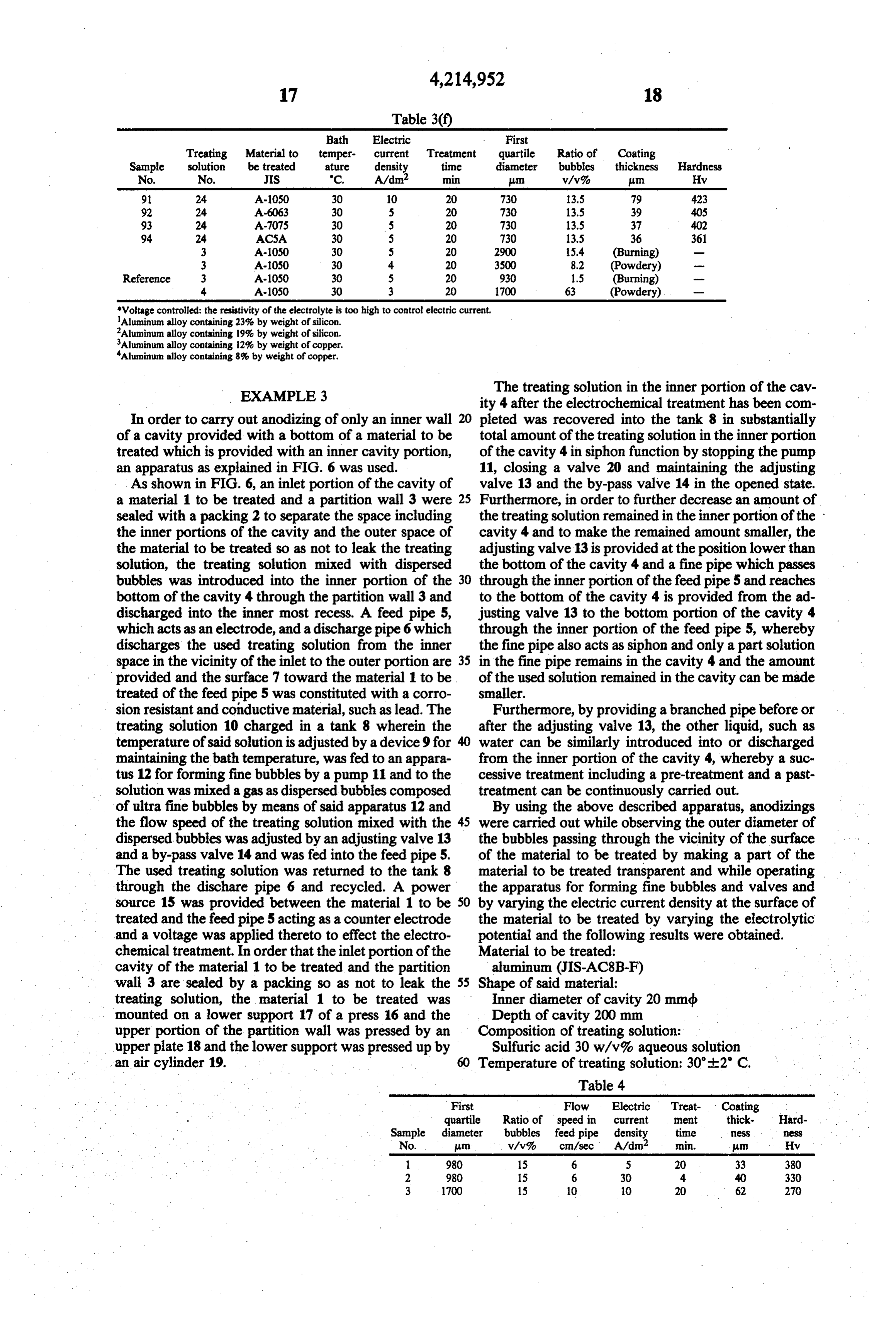
Table 3(f)
Treating Material to temper- current Treatment quartile Ratio of Coating Sample solution be treated ature density time diameter bubbles thickness Hardness No. No. IS C. A/dm? min pum v/v% Am Hy 9 24 A-1050 30 10 20 730 3.5 79 423 92 24 A-6063 30 5 20 730 13.5 39 40S 93 24 A 7075 30 s 20 730 13.5 37 402 94. 24 ACSA 30 5 20 730 13.5 36 361 3 A-1050 30 5 20 29OO 5.4 (Burning) 3 A-1050 30 4. 20 3500 8.2 (Powdery) Reference 3 A 1050 30 5 20 930 1.5 (Burning) 4. A-1050 30 3 20 700 63 (Powdery) WW Voltage controlled: the resistivity of the electrolyte is too high to control electric current, Aluminum alloy containing 23% by weight of silicon.
Aluminum alloy containing 19% by weight of silicon.
Aluminum alloy containing 12% by weight of copper.
Aluminum alloy containing 8% by weight of copper.
EXAMPLE 3 The treating solution in the inner portion of the cav ity 4 after the electrochemical treatment has been com
In order to carry out anodizing of only an inner wall pleted was recovered into the tank 8 in substantially of a cavity provided with a bottom of a material to be total amount of the treating solution in the inner portion treated which is provided with an inner cavity portion, of the cavity 4 in siphon function by stopping the pump an apparatus as explained in FIG. 6 was used. 11, closing a valve 20 and maintaining the adjusting As shown in FIG. 6, an inlet portion of the cavity of valve 13 and the by-pass valve 14 in the opened state. a material 1 to be treated and a partition wall 3 were 25 Furthermore, in order to further decrease an amount of sealed with a packing 2 to separate the space including the treating solution remained in the inner portion of the the inner portions of the cavity and the outer space of cavity 4 and to make the remained amount smaller, the the material to be treated so as not to leak the treating adjusting valve 13 is provided at the position lower than solution, the treating solution mixed with dispersed the bottom of the cavity 4 and a fine pipe which passes bubbles was introduced into the inner portion of the 30 through the inner portion of the feed pipe 5 and reaches bottom of the cavity 4 through the partition wall 3 and to the bottom of the cavity 4 is provided from the ad discharged into the inner most recess. A feed pipe 5, justing valve 13 to the bottom portion of the cavity 4 which acts as an electrode, and a discharge pipe 6 which through the inner portion of the feed pipe 5, whereby discharges the used treating solution from the inner the fine pipe also acts as siphon and only a part solution space in the vicinity of the inlet to the outer portion are 35 in the fine pipe remains in the cavity 4 and the amount provided and the surface 7 toward the material 1 to be of the used solution remained in the cavity can be made treated of the feed pipe 5 was constituted with a corro smaller.
sion resistant and conductive material, such as lead. The Furthermore, by providing a branched pipe before or treating solution 10 charged in a tank 8 wherein the after the adjusting valve 13, the other liquid, such as temperature of said solution is adjusted by a device 9 for water can be similarly introduced into or discharged maintaining the bath temperature, was fed to an appara from the inner portion of the cavity 4, whereby a suc tus 12 for forming fine bubbles by a pump 11 and to the cessive treatment including a pre-treatment and a past solution was mixed a gas as dispersed bubbles composed treatment can be continuously carried out. of ultra fine bubbles by means of said apparatus 12 and By using the above described apparatus, anodizings the flow speed of the treating solution mixed with the 45 were carried out while observing the outer diameter of dispersed bubbles was adjusted by an adjusting valve 13 the bubbles passing through the vicinity of the surface and a by-pass valve 14 and was fed into the feed pipe 5. of the material to be treated by making a part of the The used treating solution was returned to the tank 8 material to be treated transparent and while operating through the dischare pipe 6 and recycled. A power the apparatus for forming fine bubbles and valves and source 15 was provided between the material 1 to be 50 by varying the electric current density at the surface of treated and the feed pipe 5 acting as a counter electrode the material to be treated by varying the electrolytic and a voltage was applied thereto to effect the electro potential and the following results were obtained. chemical treatment. In order that the inlet portion of the Material to be treated:
cavity of the material 1 to be treated and the partition aluminum (JIS-AC8B-F) wall 3 are sealed by a packing so as not to leak the 55 Shape of said material:
treating solution, the material 1 to be treated was Inner diameter of cavity 20 mmdb mounted on a lower support 17 of a press 16 and the Depth of cavity 200 mm upper portion of the partition wall was pressed by an Composition of treating solution:
upper plate 18 and the lower support was pressed up by Sulfuric acid 30 w/v% aqueous solution an air cylinder 19. 60 Temperature of treating solution: 30'2' C. m Table 4 First Flow Electric Treat- Coating quartile Ratio of speed in current et thick- Hard
Sample diameter bubbles feed pipe density time less ess
No. an w/v% cm/sec A/dm min. in Hy
3 1700 15 O 10 20 62 270
Page 15
Table 4-continued
First Flow Electric Treat- Coating quartile Ratio of speed in current net thick- Hard
Sample diameter bubbles feed pipe density time ESS CSS
No. um v/v% cm/sec A/dm min. trn Hv 4 1700 15 O 20 O 63 250
In this case, the anode was separated by a diaphragm 10 and exposed to the dispersed bubbles in the same man
EXAMPLE 4 ner as in the cathode (material to be treated).
Copper sulfate plating was carried out under the SE E.g.rate 100 g/1 following condition. Potassium pyrophosphate: 340 g/1 Copper sulfate CuSO4.5H2O: 220 g/1 15 Ammonia EP (specific gy 0.88): 4 ml/1 Sulfuric acid H2SO4: 55 g/1 Bath temperature: 50 C.
SRA g/ The results of the obtained throwing power (%) are The obtained results are shown in Tables 5 and 6. shown in the following Table 7. Table 5 shows the apperarance of copper plating and Table 7 Table 6 shows electrolytic
resistance of the bath. Con
Table 5 process invention Conventional Present First quartile -- 990 1,050 1,160 process invention diameter (um)
First quartile - 980 1,100 25 Ratio of bub- 0. 7.2 12.0 15.2 diameter (um) bles (v/v%)
Ratio of O 11.7 15.0 2 20 9 26 32 bubbles (v/v%) Electric dark Bright Bright Bright current 6 powder 20 3. 39 4 density
Smooth Smooth Smooth 30 at Cathode 10 - - 37 44 Semi-bright Bright Bright A/dm?
8 14 --- - 50
Electric 12 Dark Bright Bright The above Table 7 shows that the covering power is current Mat Smooth Smooth as improved to above two times as high as the conven density tional process and the current efficiency at anode at the at cathode 4. - Dull bright Dull bright electric current densities at cathode of 2 A/dm2, in the (A/dm?) Mat Smooth case of the ratio of bubbles being 0, 7.2, 12.0 or 15.2 Dark Dull bright v/v% is 40, 68,87 and 90% respectively and the current
efficiency at anode is noticeably improved.
20 - - Park EXAMPLE 6
In order to examine the effect to the throwing power of nickel plating under the following bath condition,
Table 6 45 Haring cell test was carried out.
Electric In this case, the Haring cell has no bottom and the
First current Electrolytic cell was arranged just above the porous body forming quartile Ratio of density resistance bubbles.
dist by: atShe of t bath Nickel sulfate: 240 g/1
Conventional 0 4. 1.93 so Nickel chloride: 30 g/1 process Boric acid: 30 g/1 Present 980 11.7 4 1.44 Sodium 1,5-nephthalene-disulfonate: 1 g/1 invention 1,100 15.0 4 1.39 2 butyne-1,4-diol: 0.1 g/1
From Table 5 it can be seen that the limiting electric 55 Bath temperature: 55' C. current density is increased about two times by expos- Size of electrode: 50x20 mm ing to gas. Therefore, according to the treatment pro- Ratio of distance between electrodes: 5:1 cess of the present invention, it is possible to increase The obtained results are shown in the following the productivity about two times. Table 8.
According to Table 6, since the electrolytic resis- 60 Table 8 tance of the bath decreases, it is possible to lower the First electrolytic potential against the same electric current quartile Ratio of Total Throwing amount, so that the treatment can be effected by a small diameter bubbles current power electric power and the energy can be saved. No. (pm) (v/v%) A % 65 Conventional - O 0.2 39
EXAMPLE 5 process
Copper pyrophosphate plating was effected under 960 iss 8: : the condition as described hereinafter. Present 2 960 10.5 0.6 72
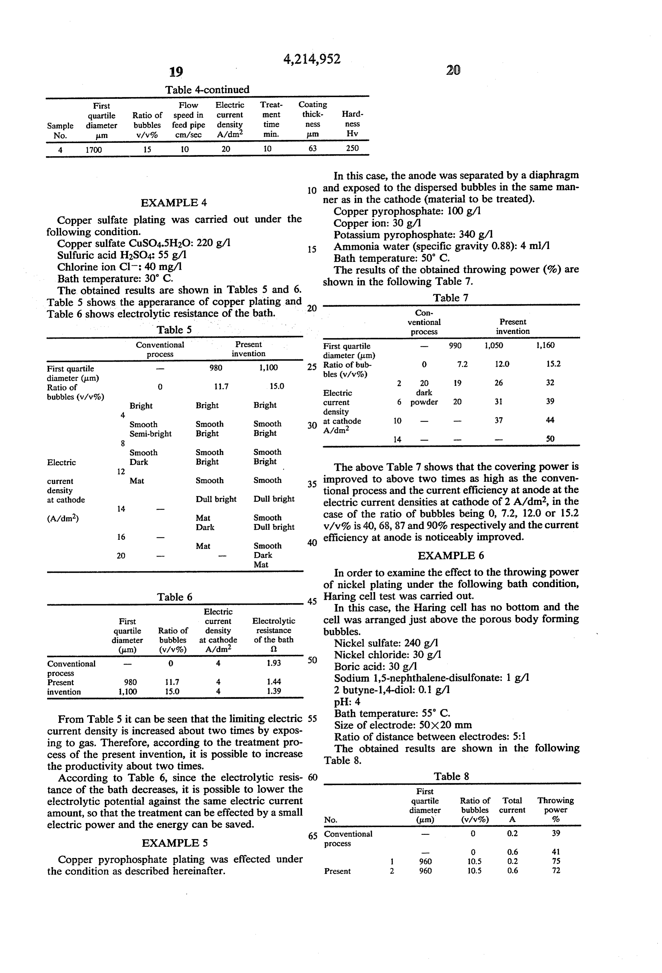
Page 16
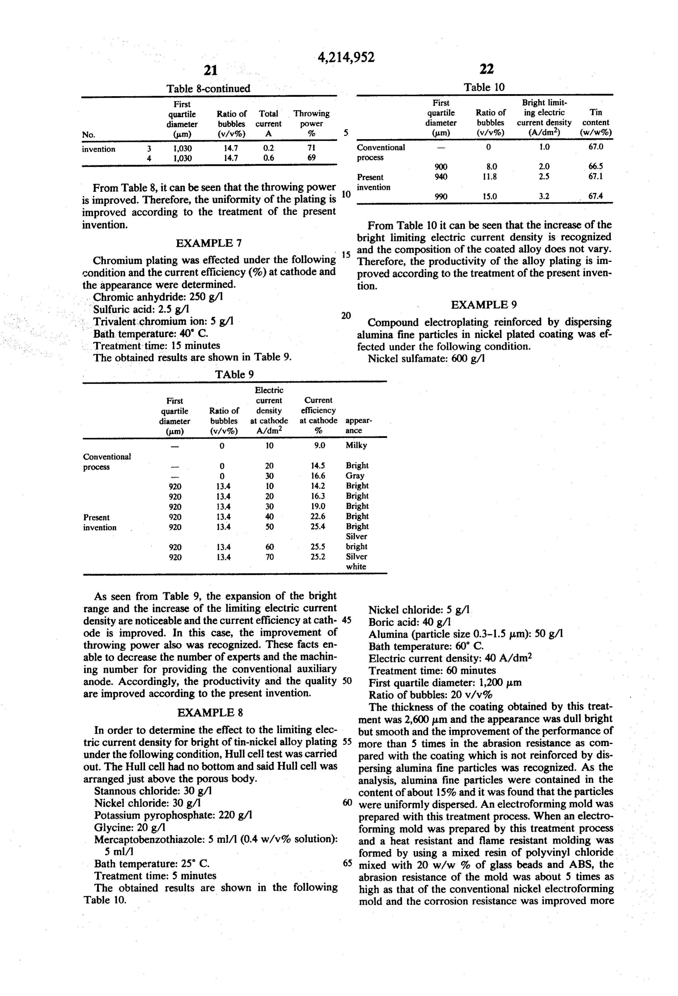
Table 8-continued Table 10
First First Bright limit quartile Ratio of Total Throwing quartile Ratio of ing electric Tin diameter bubbles current power diameter bubbles current density content No. (um) (v/v%) A % 5 (um) (v/v%) (A/dm’) (w/w%) invention 3 1,030 14.7 0.2 7 Conventional - 0 1.0 67.0 4. 030 14.7 0.6 69 process
Present 940 1.8 2.5 67.1
From Table 8, it can be seen that the throwing power invention is improved. Therefore, the uniformity of the plating is 10 990 S.0 3.2 67.4 improved according to the treatment of the present invention. From Table 10 it can be seen that the increase of the EXAMPLE 7 bright limiting electric current density is recognized 5 and the composition of the coated alloy does not vary.
Chromium plating was effected under the following 1 Therefore, the productivity of the alloy plating is im condition and the current efficiency (%) at cathode and proved according to the treatment of the present inven the appearance were determined. tion.
. . Chromic anhydride: 250 g/1 EXAMPLE 9
Trivalent chromium ion: 5 g/1 Compound electroplating reinforced by dispersing Bath temperature: 40' C. alumina fine particles in nickel plated coating was ef Treatment time: 15 minutes fected under the following condition. The obtained results are shown in Table 9. Nickel sulfamate: 600 g/1
TAble 9
Electric
quartile Ratio of density efficiency diameter bubbles at cathode at cathode appear
Conventional process - O 20 14.5 Bright
Present 920 3.4 40 22.6 Bright invention 920 13.4 50 25.4 Bright
Silver
white
As seen from Table 9, the expansion of the bright range and the increase of the limiting electric current Nickel chloride: 5 g/1 density are noticeable and the current efficiency at cath- 45 Boric acid: 40 g/l ode is improved. In this case, the improvement of Alumina (particle size 0.3-1.5 m): 50 g/1 throwing power also was recognized. These facts en Bath temperature: 60' C. able to decrease the number of experts and the machin Electric current density: 40A/dm2 ing number for providing the conventional auxiliary Treatment time: 60 minutes anode. Accordingly, the productivity and the quality 50 First quartile diameter: 1,200 am are improved according to the present invention. Ratio of bubbles: 20 v/v% EXAMPLE 8 The thickness of the coating obtained by this treat ment was 2,600 um and the appearance was dull bright
In order to determine the effect to the limiting elec but smooth and the improvement of the performance of tric current density for bright of tin-nickel alloy plating 55 more than 5 times in the abrasion resistance as com under the following condition, Hull cell test was carried pared with the coating which is not reinforced by dis out. The Hull cell had no bottom and said Hull cell was persing alumina fine particles was recognized. As the arranged just above the porous body. analysis, alumina fine particles were contained in the Stannous chloride: 30 g/1 content of about 15% and it was found that the particles Nickel chloride: 30 g/1 were uniformly dispersed. An electroforming mold was Potassium pyrophosphate: 220 g/1 prepared with this treatment process. When an electro Glycine: 20 g/1 forming mold was prepared by this treatment process Mercaptobenzothiazole: 5 ml/l (0.4 w/v% solution): and a heat resistant and flame resistant molding was 5 ml/ formed by using a mixed resin of polyvinyl chloride Bath temperature: 25 C. 65 mixed with 20 w/w % of glass beads and ABS, the Treatment time: 5 minutes abrasion resistance of the mold was about 5 times as The obtained results are shown in the following high as that of the conventional nickel electroforming Table 10. mold and the corrosion resistance was improved more
Page 17
than about 4 times and the durable life of the mold was 5 w/v% of citric acid was fed into the space between elongated. both the electrodes in an average flow speed of 15 This shows that according to the treatment of the m/sec and the electrolysis was effected. When the treat. present invention, the effect is developed in the dispers ment was effected by containing about 10 wav% of file ing and reinforcing plating and the commercially valu- 5 bubbles (the first quartile diameter of 1,500 am) in the able effect can be brought about. treating solution, the feed speed was permitted to be 7
EXAMPLE 10 In the conventional treatment wherein the fine bub
Electrolytic refining of copper was effected as the bles according to the present invention are not con electrochemical treatment according to the present 10 tained in the treating solution, if the current density was invention. The treatment condition and the results are raised so as to increase the feed speed to more than 3 shown in the following Table 11. mm/min., the electrolyte solution boiled and the dis Table 11 charge occured and the treatment becaze infeasible.
Accordingly, in this example, the treataeai was a bie
Conventional Present 15 to be effected in a speed of 2 times as ligh as the coil process invention
Electrolyte solution ventional process.
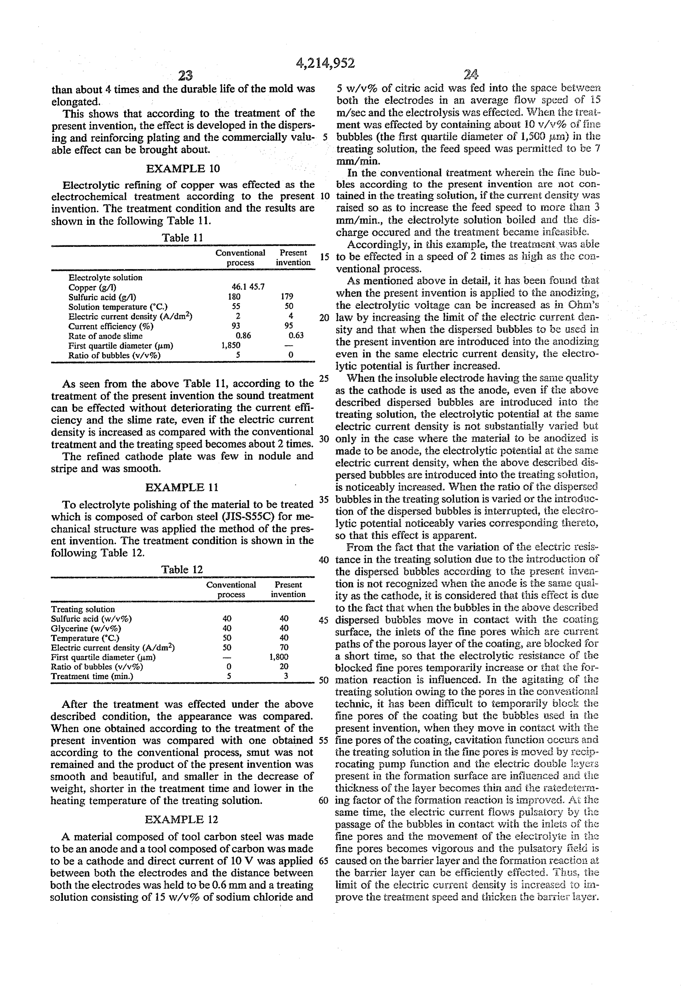
Copper (g/l) 46,145.7 As mentioned above in detail, it has beei found that Sulfuric acid (g/t) 18O 79 when the present invention is applied to the anodizing, Solution temperature (C.) 55 50 the electrolytic voltage can be increased as in Chri's Electric current density (A/dm’) 2 4. 20 law by increasing the limit of the electric cuis rent den Current efficiency (%) 93 95 sity and that when the dispersed bubbles to be used in
First quartile diameter (um) 1,850 - the present invention are introduced into the anodizing Ratio of bubbles (v/v%) 5 0 even in the same electric current density, the electro lytic potential is further increased.
As seen from the above Table 11, according to the 25 as When the the insoluble electrode having the saile quality cathode is used as the anode, even if tire above treatment of the present invention the sound treatment described dispersed can be effected without deteriorating the current effi treating solution, the bubbles are introduced into the electrolytic potential at the same ciency and the slime rate, even if the electric current electric current density is not substantially varied but density is increased as compared with the conventional only in the case where the material to be anodized is treatment and the treating speed becomes about 2 times. 30 made
The refined cathode plate was few in nodule and electric current density, when the potential to be anode, the electrolytic at the same above described dis stripe and was smooth. persed bubbles are introduced into the treating solation, EXAMPLE 11 is noticeably increased. When the ratio of the dispersed 35 bubbles in the treating solution is varied or the introdic
To electrolyte polishing of the material to be treated tion of the dispersed bubbles is interrupted, the electro which is composed of carbon steel (JIS-S55C) for me lytic potential noticeably varies corresponding thereto, chanical structure was applied the method of the pres so that this effect is apparent. ent invention. The treatment condition is shown in the From the fact that the variation of the electric resis following Table 12. 40 tance in the treating solution due to the introduction of Table 12 the dispersed bubbles according to the present inven
Conventional Present tion is not recognized when the anode is the saiae qual process invention ity as the cathode, it is considered that this effect is due
Treating solution to the fact that when the bubbles in the above described Sulfuric acid (w/v%) 40 40 45 dispersed bubbles move in contact with the coating Glycerine (w/v%) 40 40 surface, the inlets of the fine pores wirich are cirrent
Electric current density (A/dm?) 50 70 paths of the porous layer of the coating, are blocked for First quartile diameter (m) run 1,800 a short time, so that the electrolytic resistance of the Ratio of bubbles (va v%) O 20 blocked fine pores temporarily increase or that iiie for Treatment time (min.) 5 3 50 nation reaction is influenced. In the agitating of the treating solution owing to the pores in the convexitio; all
After the treatment was effected under the above technic, it has been difficult to temporarily block the described condition, the appearance was compared. fine pores of the coating but the bubbles assed in the When one obtained according to the treatment of the present invention, when they move in contact with the present invention was compared with one obtained 55 fine pores of the coating, cavitation function occurs ani according to the conventional process, smut was not the treating solution in the fine pores is noved by recip remained and the product of the present invention was rocating pump function and the electric double layers smooth and beautiful, and smaller in the decrease of present in the formation surface are influenced aid tie weight, shorter in the treatment time and lower in the thickness of the layer becomes thin and the raiedeters heating temperature of the treating solution. 60 ing factor of the formation reaction is improved. As he EXAMPLE 12 same time, the electric current flows pulsatory y tie passage of the bubbles in contact with the inleis of th:2
A material composed of tool carbon steel was made fine pores and the movement of the electrolyte is the to be an anode and a tool composed of carbon was made fine pores becomes vigorous and the pulsatory field is to be a cathode and direct current of 10 V was applied 65 caused on the barrier layer and the formation eaction at between both the electrodes and the distance between the barrier layer can be efficiently effected. This, tie both the electrodes was held to be 0.6 mm and a treating limit of the electric current density is increased to ign solution consisting of 15 w/v% of sodium chloride and prove the treatment speed and thicketi the barrier layer.
Page 18
Accordingly, the number of the fine pores per unit area sium alloys, titanium, titanium alloys, zirconium and of the coating decreases and the coating becomes dense, zirconium alloys as one of the electrodes. so that the hardness increases and the abrasion resis 7. The process as claimed in claim 6, wherein the tance is improved. metal is selected from the group consisting of aluminum When the present invention is applied to the electro and aluminum alloys.
lytic precipitation or electrolytic dissolution, as men 8. An electrolytic precipitation process in which a tioned above the treatment speed is increased and the current density of 3-170A/dm is applied while form ing bubbles in a treating solution at a temperature of productivity is not only increased, but also the quality 0-100' of the treated product is improved and the present in 10 dispersedC.,bubbles which comprises containing 2-60V/V% of having first quartile diameter being vention is commercially very advantageous. not more than 2,000 um in the treating solution. What is claimed is: 9. The process as claimed in claim 8, wherein the 1. An anodizing process in which a current density of electrolytic precipitation is electrolytic plating. 3-170 A/dm2 is applied while forming bubbles in a 10. The process as claimed in claim 8, wherein the treating solution at a temperature of 0-100' C., which 15 electrolytic precipitation is electrolytic refining. comprises containing 2-60V/V% of dispersed bubbles 11. The process as claimed in claim 8, wherein the having first quartile diameter being not more than 2,000 first quartile diameter is not more than 1,000 um. um in the treating solution. 12. The process as claimed in claim 8, wherein the 2. The process as claimed in claim 1, wherein the first treating solution contains 2-30 V/V% of dispersed quartile diameter is not more than 1,000 um. 20 bubbles.
3. The process as claimed in claim 1, wherein the 13. An electrolytic dissolution process in which a treating solution contains 2-30 v/v% of dispersed bub currenting density of 3-170A/dm2 is applied while form bubbles in a treating solution at a temperature of bles.
4. The process as claimed in claim 1, wherein the 25 dispersed bubbles comprises
treating solution is at least one acid selected from the not more than 2,000 um in the quartile having first treating diameter being solution.
group consisting of sulfuric acid, oxalic acid, phos 14. The process as claimed in claim 13, wherein the phoric acid, benzenesulfonic acid, sulfamic acid, boric electrolytic dissolution is electrolytic polishing. acid, ammonium borate, citric acid, tartaric acid, formic 15. The process as claimed in claim 13, wherein the acid, succinic acid and chromic acid. 30 electrolytic dissolution is electrolytic machining. 5. The process as claimed in claim 4, wherein the acid 16. The process as claimed in claim 13, wherein the is sulfuric acid or oxalic acid. first quartile diameter is not more than 1,000 um. 6. The process as claimed in claim 1, wherein the 17. The process as claimed in claim 13, wherein the anodizing is effected by using at least one metal selected treating solution contains 2-30 V/V% of dispersed from the group consisting of aluminum, aluminum al 35 bubbles.
loys, beryllium, beryllium alloys, magnesium, magne
Provenance
- Collection
- Cited prior art
- Original PDF
- patentimages.storage.googleapis.com →
- Filed
- 1978-07-31
- Pages
- 18
- Method
- pdftotext (the PDF's own text layer) + pdftoppm 300dpi page scans
- Source
- Google Patents bibliographic record
- Granted
- 1980-07-29
- Inventors
- Mitsuhiro Sato; Noboru Kasahara; NGK Insulators Ltd
- Transcribed from
- patentimages.storage.googleapis.com →