patent · US4258698A
Solar heating apparatus
31 March 1981
Page 1 — bibliographic record
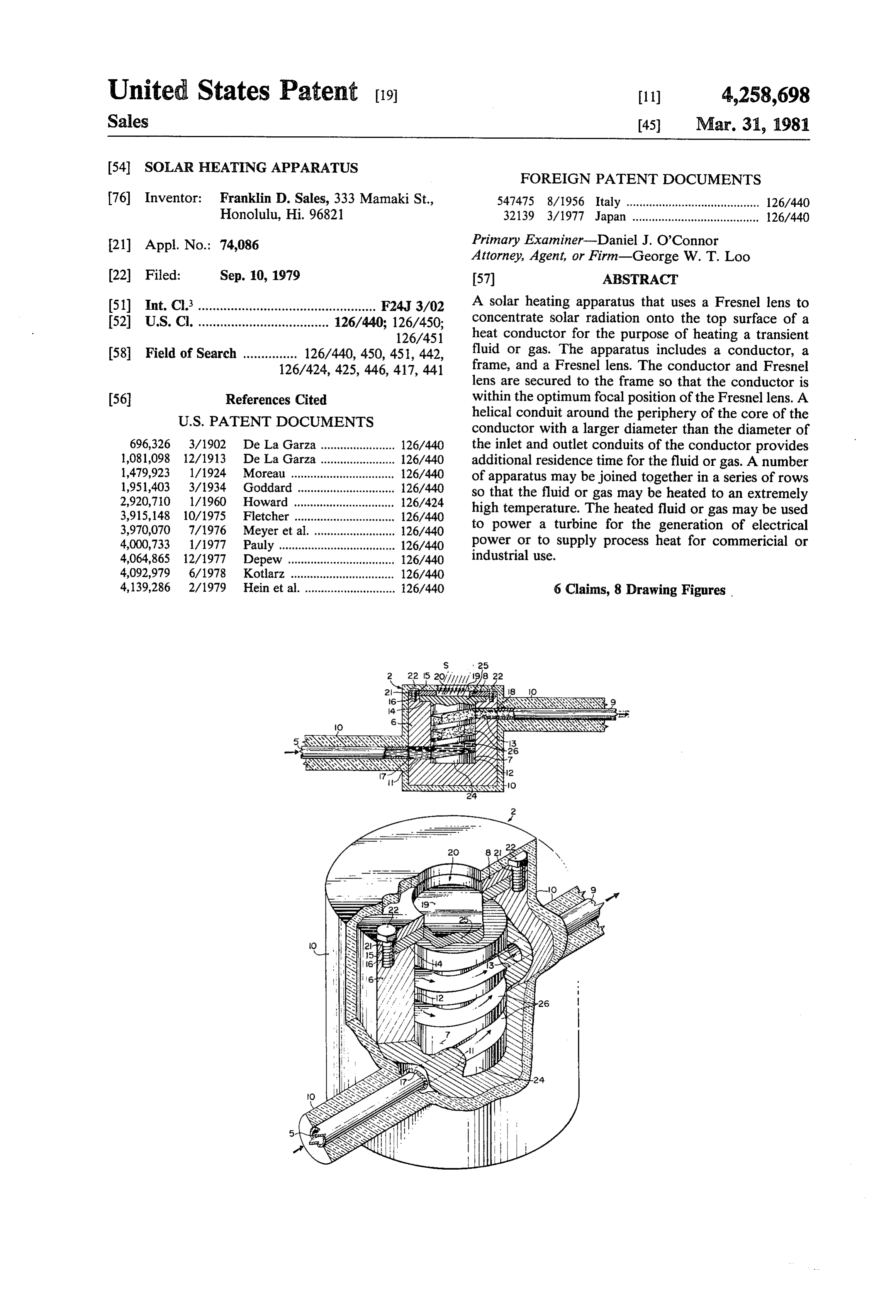
United States Patent (19) 11) 4,258,698 Sales 45) Mar. 31, 1981 54). SOLAR HEATING APPARATUS FOREIGN PATENT DOCUMENTS 76) Inventor: Franklin D. Sales, 333 Mamaki St., 547475 8/1956 Italy ......................................... 126/440 Honolulu, Hi. 96821 32139 3/1977 Japan ....................................... 126/440 21 Appl. No.: 74,086 Primary Examiner-Daniel J. O'Connor Attorney, Agent, or Firm-George W. T. Loo 22 Filed: Sep. 10, 1979 57) ABSTRACT 51) Int. Cl.................................................. F24J 3/02 A solar heating apparatus that uses a Fresnel lens to 52 U.S. C. .................................... 126/440; 126/450; concentrate solar radiation onto the top surface of a 126/451 heat conductor for the purpose of heating a transient 58 Field of Search ............... 126/440, 450, 451, 442, fluid or gas. The apparatus includes a conductor, a 126/424, 425, 446, 417, 441 frame, and a Fresnel lens. The conductor and Fresnel lens are secured to the frame so that the conductor is (56) References Cited within the optimum focal position of the Fresnel lens. A
conductor with a larger diameter than the diameter of 696,326 3/1902 De La Garza ....................... 126/440 the inlet and outlet conduits of the conductor provides 1,081,098 12/1913 De La Garza ... 126/440 additional residence time for the fluid or gas. A number 1,479,923 1/1924 Moreau ......... ... 126/440 of apparatus may be joined together in a series of rows 1,951,403 3/1934 Goddard ... ... 126/440 so that the fluid or gas may be heated to an extremely 2,920,710 1/1960 Howard ... ... 126/424 high temperature. The heated fluid or gas may be used 3,915,148 10/1975 Fletcher ........ ... 126/440 3,970,070 7/1976 Meyer et al. ... 126/440 to power a turbine for the generation of electrical 4,000,733 1/1977 Pauly ......... ... 126/440 power or to supply process heat for commericial or 4,064,865 12/1977 Depew. ... 126/440 industrial use.
4,092,979 6/1978 Kotlarz ..... ... 126/440 4,139,286 2/1979 Hein et al. ............................ 26/440 6 Claims, 8 Drawing Figures
SSSSSS
Page 2
Drawing sheet — no readable text.
Page 3
Drawing sheet — no readable text.
Page 4
Drawing sheet — no readable text.
Page 5
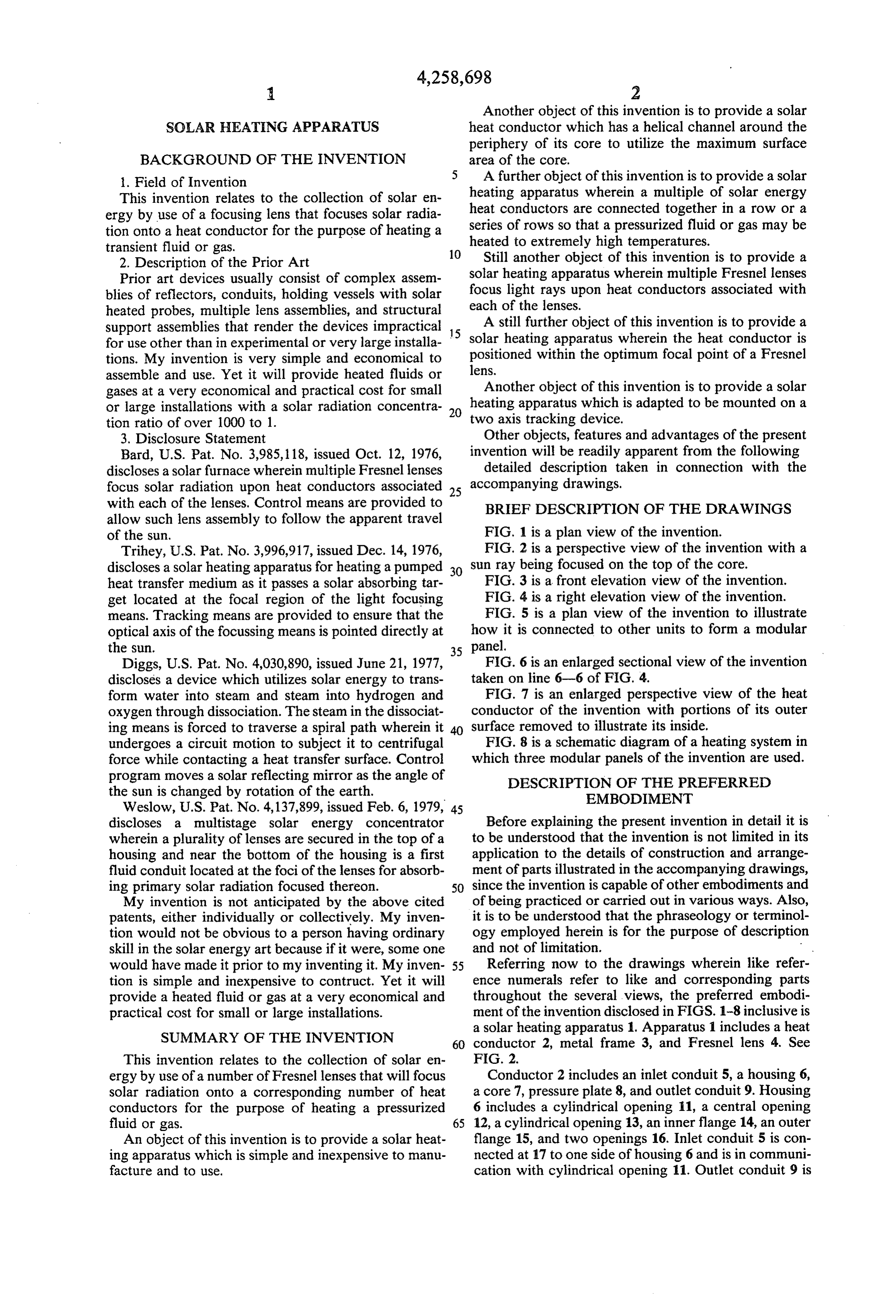
Another object of this invention is to provide a solar
SOLAR HEATHINGAPPARATUS heat conductor which has a helical channel around the periphery of its core to utilize the maximum surface
BACKGROUND OF THE INVENTION area of the core.
Field of Invention A further object of this invention is to provide a solar This invention relates to the collection of solar en heating apparatus wherein a multiple of solar energy ergy by use of a focusing lens that focuses solar radia heat conductors are connected together in a row or a tion onto a heat conductor for the purpose of heating a series of rows so that a pressurized fluid or gas may be heated to extremely high temperatures.
transient fluid or gas. 10 Still another object of this invention is to provide a 2. Description of the Prior Art
Prior art devices usually consist of complex assem solar heating apparatus wherein multiple Fresnel lenses blies of reflectors, conduits, holding vessels with solar focus light rays upon heat conductors associated with heated probes, multiple lens assemblies, and structural each of the lenses.
support assemblies that render the devices impractical 15 A still further object of this invention is to provide a for use other than in experimental or very large installa solar heating apparatus wherein the heat conductor is tions. My invention is very simple and economical to lens. positioned within the optimum focal point of a Fresnel assemble and use. Yet it will provide heated fluids or gases at a very economical and practical cost for small Another object of this invention is to provide a solar or large installations with a solar radiation concentra 20 heating apparatus which is adapted to be mounted on a tion ratio of over 1000 to 1. two axis tracking device.
3. Disclosure Statement Other objects, features and advantages of the present Bard, U.S. Pat. No. 3,985, 118, issued Oct. 12, 1976, invention will be readily apparent from the following discloses a solar furnace wherein multiple Fresnel lenses detailed description taken in connection with the focus solar radiation upon heat conductors associated 25 accompanying drawings.
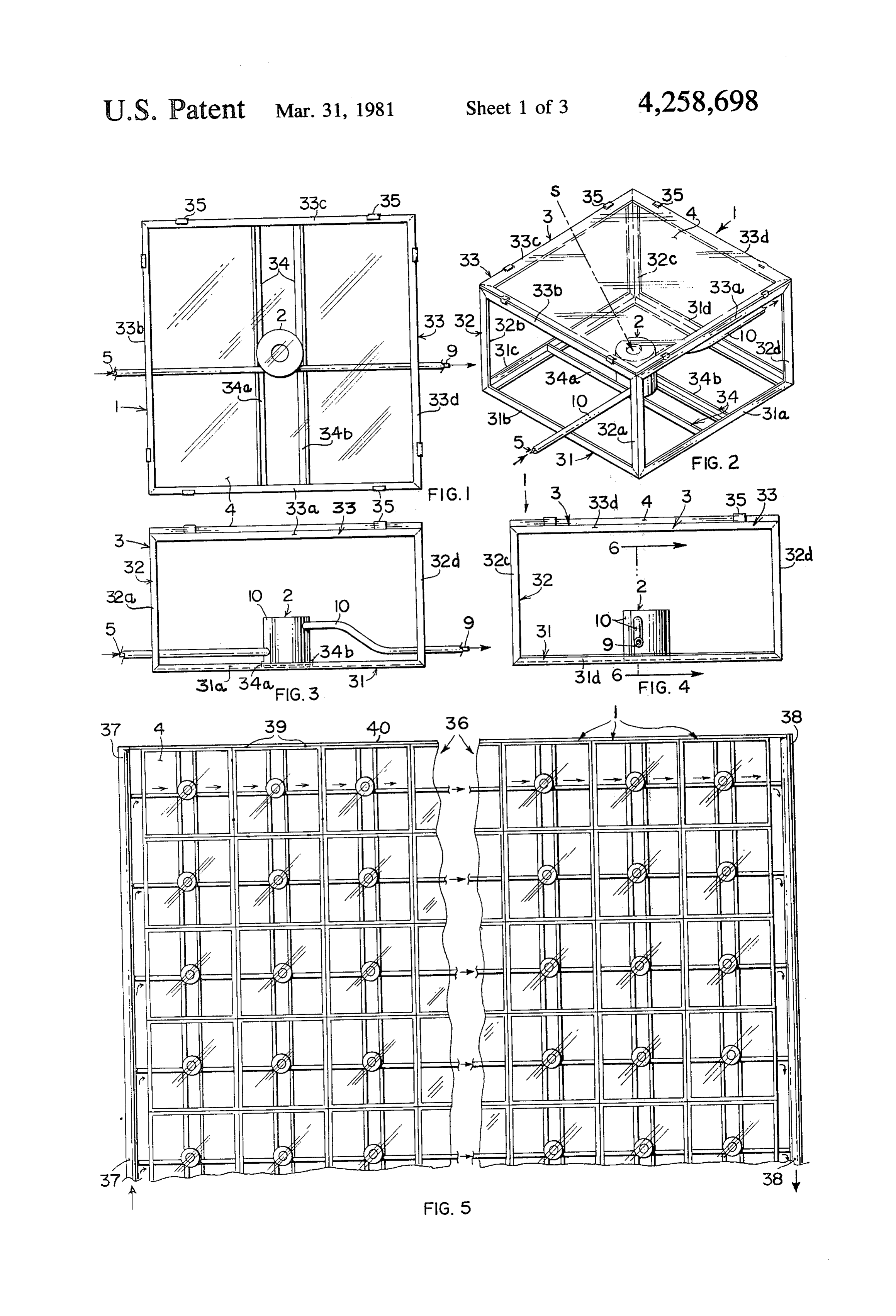
with each of the lenses. Control means are provided to BRIEF DESCRIPTION OF THE DRAWINGS allow such lens assembly to follow the apparent travel of the sun. FIG. 1 is a plan view of the invention. Trihey, U.S. Pat. No. 3,996,917, issued Dec. 14, 1976, FIG. 2 is a perspective view of the invention with a discloses a solar heating apparatus for heating a pumped 30 sun ray being focused on the top of the core. heat transfer medium as it passes a solar absorbing tar FIG. 3 is a front elevation view of the invention. get located at the focal region of the light focusing FIG. 4 is a right elevation view of the invention. means. Tracking means are provided to ensure that the FIG. 5 is a plan view of the invention to illustrate optical axis of the focussing means is pointed directly at how it is connected to other units to form a modular the sun. 35 panel.
Diggs, U.S. Pat. No. 4,030,890, issued June 21, 1977, FIG. 6 is an enlarged sectional view of the invention discloses a device which utilizes solar energy to trans taken on line 6-6 of FIG. 4.
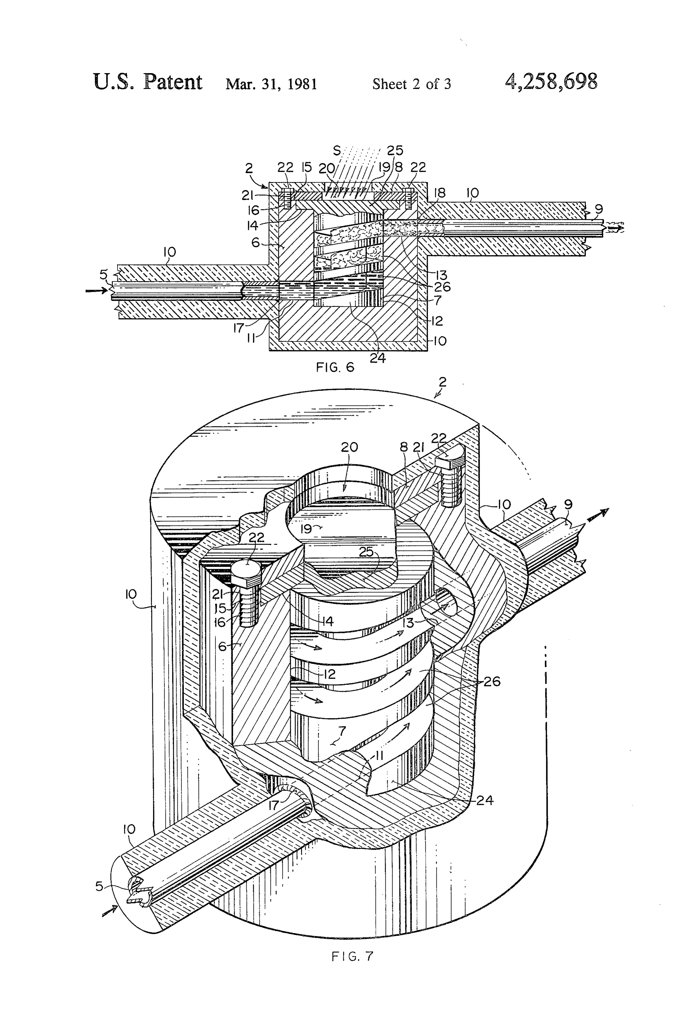
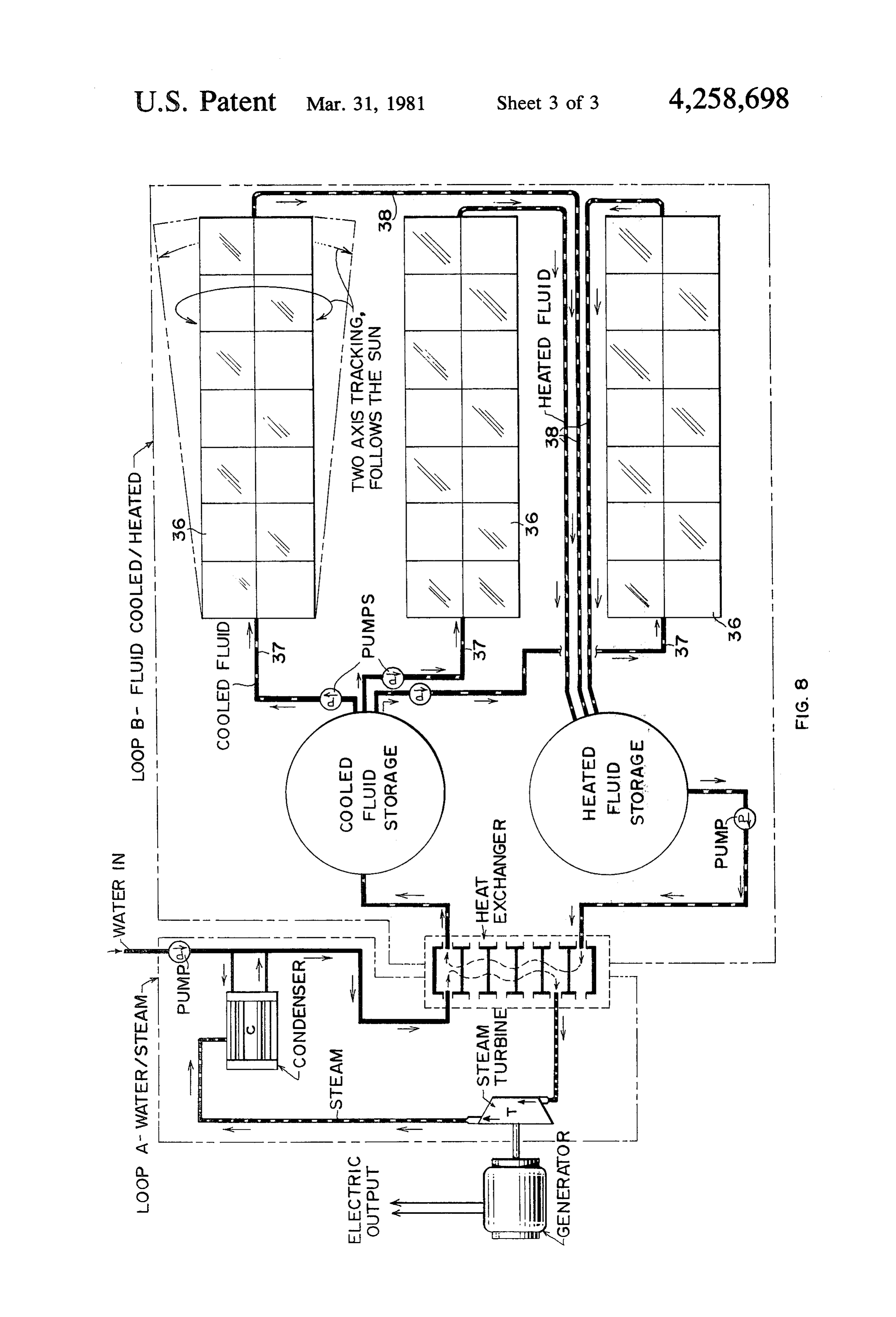
form water into steam and steam into hydrogen and FIG. 7 is an enlarged perspective view of the heat oxygen through dissociation. The steam in the dissociat conductor of the invention with portions of its outer ing means is forced to traverse a spiral path wherein it surface removed to illustrate its inside. undergoes a circuit motion to subject it to centrifugal FIG. 8 is a schematic diagram of a heating system in force while contacting a heat transfer surface. Control which three modular panels of the invention are used. program moves a solar reflecting mirror as the angle of DESCRIPTION OF THE PREFERRED the sun is changed by rotation of the earth. EMBO)IMENT
discloses a multistage solar energy concentrator Before explaining the present invention in detail it is wherein a plurality of lenses are secured in the top of a to be understood that the invention is not limited in its housing and near the bottom of the housing is a first application to the details of construction and arrange fluid conduit located at the foci of the lenses for absorb ment of parts illustrated in the accompanying drawings, ing primary solar radiation focused thereon. 50 since the invention is capable of other embodiments and My invention is not anticipated by the above cited of being practiced or carried out in various ways. Also, patents, either individually or collectively. My inven it is to be understood that the phraseology or terminol tion would not be obvious to a person having ordinary ogy employed herein is for the purpose of descriptio skill in the solar energy art because if it were, some one and not of limitation.
would have made it prior to my inventing it. My inven 55 Referring now to the drawings wherein like refer tion is simple and inexpensive to contruct. Yet it will ence numerals refer to like and corresponding parts provide a heated fluid or gas at a very economical and throughout the several views, the preferred embodi practical cost for small or large installations. ment of the invention disclosed in FIGS. 1-8 inclusive is
SUMMARY OF THE INVENTION
a solar heating apparatus 1. Apparatus 1 includes a heat 60 conductor 2, metal frame 3, and Fresnel lens 4. See
This invention relates to the collection of solar en FIG. 2.
ergy by use of a number of Fresnel lenses that will focus Conductor 2 includes an inlet conduit 5, a housing 6, solar radiation onto a corresponding number of heat a core 7, pressure plate 8, and outlet conduit 9. Housing conductors for the purpose of heating a pressurized 6 includes a cylindrical opening 11, a central opening fluid or gas. 65 12, a cylindrical opening 13, an inner flange 14, an outer An object of this invention is to provide a solar heat flange 15, and two openings 16. Inlet conduit 5 is con ing apparatus which is simple and inexpensive to manu nected at 17 to one side of housing 6 and is in communi facture and to use. cation with cylindrical opening 11. Outlet conduit 9 is
Page 6
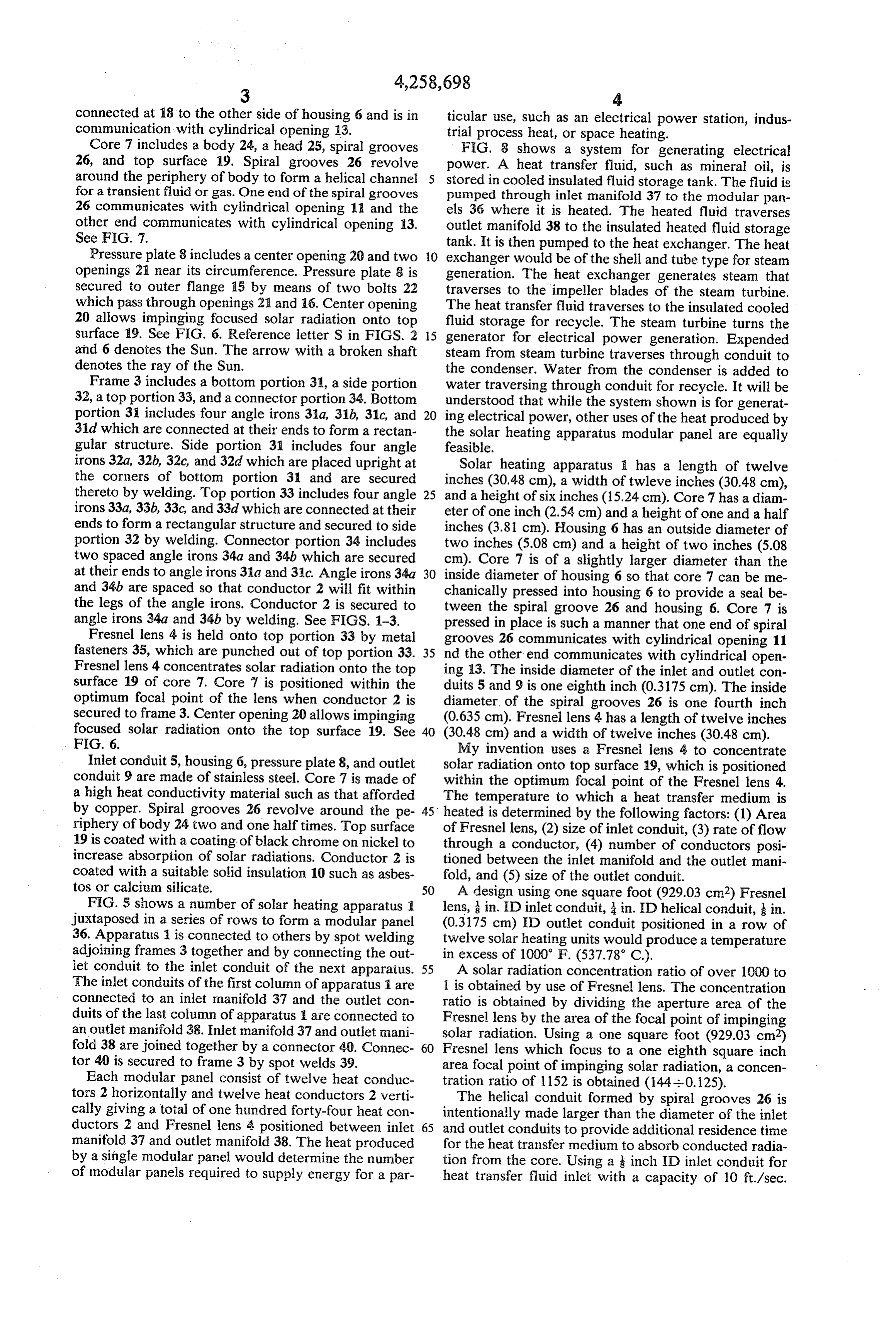
connected at 18 to the other side of housing 6 and is in ticular use, such as an electrical power station, indus communication with cylindrical opening 13. trial process heat, or space heating. Core 7 includes a body 24, a head 25, spiral grooves FIG. 8 shows a system for generating electrical 26, and top surface 19, Spiral grooves 26 revolve power. A heat transfer fluid, such as mineral oil, is around the periphery of body to form a helical channel stored in cooled insulated fluid storage tank. The fluid is for a transient fluid or gas. One end of the spiral grooves pumped through inlet manifold 37 to the modular pan 26 communicates with cylindrical opening 11 and the els 36 where it is heated. The heated fluid traverses other end communicates with cylindrical opening 13. outlet manifold 38 to the insulated heated fluid storage See FIG. 7. tank. It is then pumped to the heat exchanger. The heat Pressure plate 8 includes a center opening 20 and two 10 exchanger would be of the shell and tube type for steam openings 21 near its circumference. Pressure plate 8 is generation. The heat exchanger generates steam that secured to outer flange 15 by means of two bolts 22 traverses to the impeller blades of the steam turbine. which pass through openings 21 and 16. Center opening The heat transfer fluid traverses to the insulated cooled 20 allows impinging focused solar radiation onto top fluid storage for recycle. The steam turbine turns the Surface 9. See FIG. 6. Reference letter S in FIGS. 2 15 generator for electrical power generation. Expended and 6 denotes the Sun. The arrow with a broken shaft steam from steam turbine traverses through conduit to denotes the ray of the Sun. the condenser. Water from the condenser is added to Frame 3 includes a bottom portion 3A, a side portion water traversing through conduit for recycle. It will be 32, a top portion 33, and a connector portion 34. Bottom understood that while the system shown is for generat portion 31 includes four angle irons 31a, 31b, 31c, and 20 ing electrical power, other uses of the heat produced by 31d which are connected at their ends to form a rectan the solar heating apparatus modular panel are equally gular structure. Side portion 31 includes four angle feasible.
irons 32a, 32b, 32c, and 32d which are placed upright at Solar heating apparatus a has a length of twelve the corners of bottom portion 31 and are secured inches (30.48 cm), a width of twleve inches (30.48 cm), thereto by welding. Top portion 33 includes four angle 25 and a height of six inches (15.24 cm). Core 7 has a diam irons 33a, 33b, 33c, and 33d which are connected at their eter of one inch (2.54 cm) and a height of one and a half ends to form a rectangular structure and secured to side inches (3.81 cm). Housing 6 has an outside diameter of portion 32 by welding. Connector portion 34 includes two inches (5.08 cm) and a height of two inches (5.08 two spaced angle irons 34a and 34b which are secured cm). Core 7 is of a slightly larger diameter than the at their ends to angle irons 31a and 34c. Angle irons 34a 30 inside diameter of housing 6 so that core 7 can be me and 34b are spaced so that conductor 2 will fit within chanically pressed into housing 6 to provide a seal be the legs of the angle irons. Conductor 2 is secured to tween the spiral groove 26 and housing 6. Core 7 is angle irons 34a and 34b by welding. See FIGS. 1-3. pressed in place is such a manner that one end of spiral Fresnel lens 4 is held onto top portion 33 by metal grooves 26 communicates with cylindrical opening 11 fasteners 35, which are punched out of top portion 33. 35 nd the other end communicates with cylindrical open Fresnel lens 4 concentrates solar radiation onto the top ing 13. The inside diameter of the inlet and outlet con surface 19 of core 7. Core 7 is positioned within the duits 5 and 9 is one eighth inch (0.3175 cm). The inside optimum focal point of the lens when conductor 2 is diameter of the spiral grooves 26 is one fourth inch secured to frame 3. Center opening 20 allows impinging (0.635 cm). Fresnel lens 4 has a length of twelve inches focused solar radiation onto the top surface 19. See 40 (30.48 cm) and a width of twelve inches (30.48 cm). FIG. 6. My invention uses a Fresnel lens 4 to concentrate Inlet conduit 5, housing 6, pressure plate 8, and outlet solar radiation onto top surface 19, which is positioned conduit 9 are made of stainless steel. Core 7 is made of within the optimum focal point of the Fresnel lens 4. a high heat conductivity material such as that afforded The temperature to which a heat transfer medium is by copper. Spiral grooves 26 revolve around the pe 45 heated is determined by the following factors: (1) Area riphery of body 24 two and one halftimes. Top surface of Fresnel lens, (2) size of inlet conduit, (3) rate of flow 19 is coated with a coating of black chrome on nickel to through a conductor, (4) number of conductors posi increase absorption of solar radiations. Conductor 2 is tioned between the inlet manifold and the outlet mani coated with a suitable solid insulation 10 such as asbes fold, and (5) size of the outlet conduit. tos or calcium silicate. 50 A design using one square foot (929.03 cm2) Fresnel FIG. 5 shows a number of solar heating apparatus a lens, in. ID inlet conduit, in. ID helical conduit, in. juxtaposed in a series of rows to form a modular panel (0.3175 cm) ID outlet conduit positioned in a row of 36. Apparatus A is connected to others by spot welding twelve solar heating units would produce a temperature adjoining frames 3 together and by connecting the out in excess of 1000 F. (537.78° C.).
let conduit to the inlet conduit of the next apparatus. 55 A solar radiation concentration ratio of over 1000 to The inlet conduits of the first column of apparatus 1 are i is obtained by use of Fresnel lens. The concentration connected to an inlet manifold 37 and the outlet con ratio is obtained by dividing the aperture area of the duits of the last column of apparatus are connected to Fresnel lens by the area of the focal point of impinging an outlet manifold 38. Inlet manifold 37 and outlet mani solar radiation. Using a one square foot (929.03 cm) fold 38 are joined together by a connector 40. Connec 60 Fresnel lens which focus to a one eighth square inch tor 40 is secured to frame 3 by spot welds 39. area focal point of impinging solar radiation, a concen Each modular panel consist of twelve heat conduc tration ratio of 1152 is obtained (144--0.125). tors 2 horizontally and twelve heat conductors 2 verti The helical conduit formed by spiral grooves 26 is cally giving a total of one hundred forty-four heat con intentionally made larger than the diameter of the inlet ductors 2 and Fresnel lens 4 positioned between inlet 65 and outlet conduits to provide additional residence time manifold 37 and outlet manifold 38. The heat produced for the heat transfer medium to absorb conducted radia by a single modular panel would determine the number tion from the core. Using a inch ID inlet conduit for of modular panels required to supply energy for a par heat transfer fluid inlet with a capacity of 10 ft/sec.
Page 7
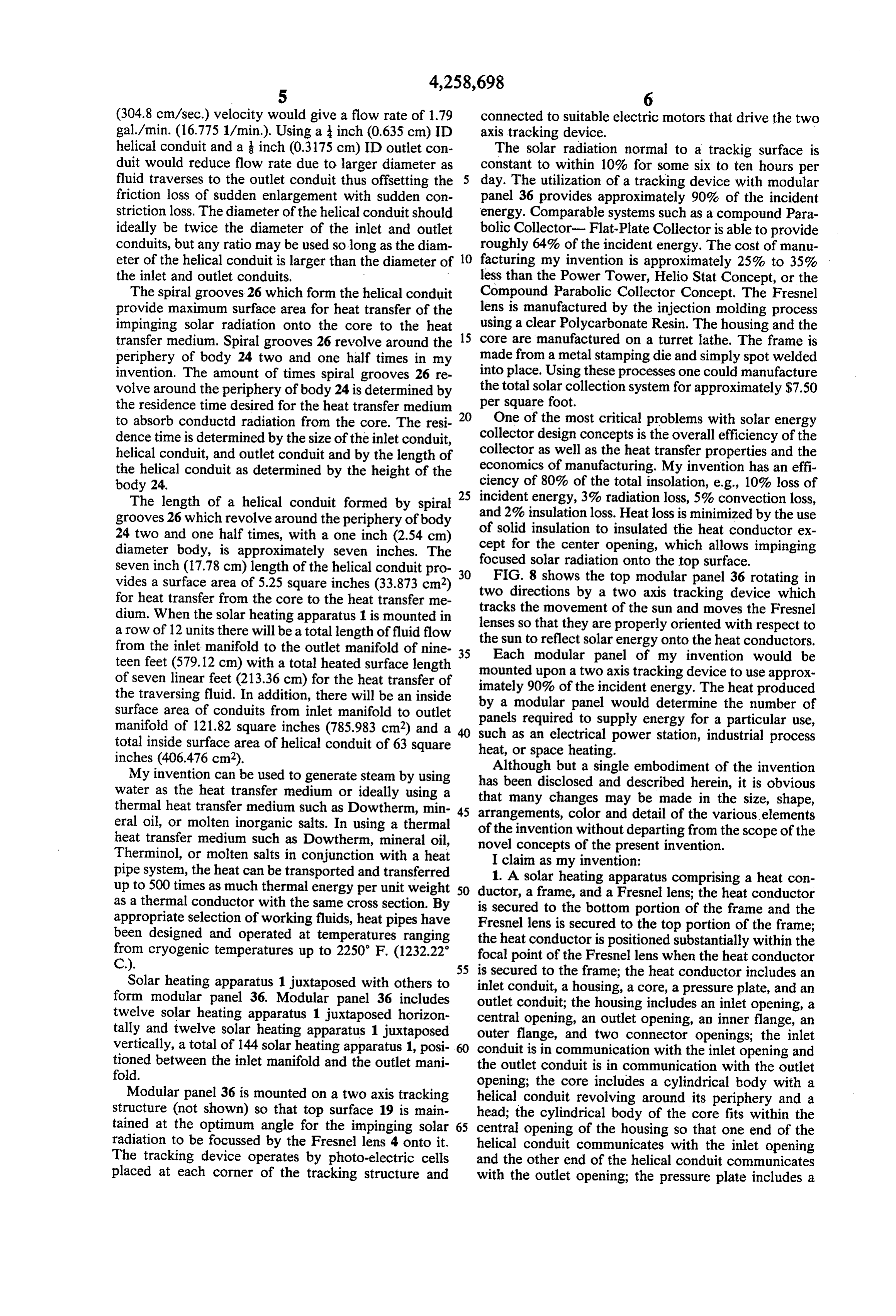
(304.8 cm/sec.) velocity would give a flow rate of 1.79 connected to suitable electric motors that drive the two gal/min. (16.775 1/min.). Using a inch (0.635 cm) ID axis tracking device.
helical conduit and a inch (0.3175 cm) ID outlet con The solar radiation normal to a trackig surface is duit would reduce flow rate due to larger diameter as constant to within 10% for some six to ten hours per fluid traverses to the outlet conduit thus offsetting the day. The utilization of a tracking device with modular friction loss of sudden enlargement with sudden con panel 36 provides approximately 90% of the incident striction loss. The diameter of the helical conduit should energy. Comparable systems such as a compound Para ideally be twice the diameter of the inlet and outlet bolic Collector- Flat-Plate Collector is able to provide conduits, but any ratio may be used so long as the diam roughly 64% of the incident energy. The cost of manu eter of the helical conduit is larger than the diameter of 10 facturing my invention is approximately 25% to 35% the inlet and outlet conduits. less than the Power Tower, Helio Stat Concept, or the The spiral grooves 26 which form the helical conduit Compound Parabolic Collector Concept. The Fresnel provide maximum surface area for heat transfer of the lens is manufactured by the injection molding process impinging solar radiation onto the core to the heat 15 using a clear Polycarbonate Resin. The housing and the transfer medium. Spiral grooves 26 revolve around the core are manufactured on a turret lathe. The frame is periphery of body 24 two and one half times in my made from a metal stamping die and simply spot welded invention. The amount of times spiral grooves 26 re into place. Using these processes one could manufacture volve around the periphery of body 24 is determined by per the total solar collection system for approximately $7.50 the residence time desired for the heat transfer medium square foot.
to absorb conductd radiation from the core. The resi 20 One of the most critical problems with solar energy dence time is determined by the size of the inlet conduit, collector design concepts is the overall efficiency of the helical conduit, and outlet conduit and by the length of collector as well as the heat transfer properties and the the helical conduit as determined by the height of the economics of manufacturing. My invention has an effi body 24. ciency of 80% of the total insolation, e.g., 10% loss of 25 incident energy, 3% radiation loss, 5% convection loss,
The length of a helical conduit formed by spiral grooves 26 which revolve around the periphery of body of and 2% insulation loss. Heat loss is minimized by the use 24 two and one half times, with a one inch (2.54 cm) ceptsolid insulation to insulated the heat conductor ex for the center opening, which allows impinging diameter body, is approximately seven inches. The focused seven inch (17.78 cm) length of the helical conduit pro 30 FIG. 8solar radiation onto the top surface. shows the top modular panel 36 rotating in vides a surface area of 5.25 square inches (33.873 cm2) two directions by a two axis tracking device which for heat transfer from the core to the heat transfer me tracks the movement of the sun and moves the Fresnel dium. When the solar heating apparatus 1 is mounted in lenses a row of 12 units there will be a total length of fluid flow the sunsotothat they are properly oriented with respect to reflect solar energy onto the heat conductors.
from the inlet manifold to the outlet manifold of nine 35 teen feet (579.12 cm) with a total heated surface length Each modular panel of my invention would be of seven linear feet (213.36 cm) for the heat transfer of mounted upon a two axis tracking device to use approx imately 90% of the incident energy. The heat produced the traversing fluid. In addition, there will be an inside by a modular panel would determine the number of surface area of conduits from inlet manifold to outlet manifold of 121.82 square inches (785.983 cm2) and a such asrequired panels to supply energy for a particular use, total inside surface area of helical conduit of 63 square heat, or space heating.power station, industrial process an electrical
My invention can be used to generate steam by using hasAlthough but a single embodiment of the invention water as the heat transfer medium or ideally using a that many changesand been disclosed may described herein, it is obvious be made in the size, shape, thermal heat transfer medium such as Dowtherm, min 45 arrangements, color and detail of the various, elements eral oil, or molten inorganic salts. In using a thermal of the invention without departing from the scope of the heat transfer medium such as Dowtherm, mineral oil,
Therminol, or molten salts in conjunction with a heat novel concepts of the present invention. I claim as my invention:
pipe system, the heat can be transported and transferred 1. A solar heating apparatus comprising a heat con up to 500 times as much thermal energy per unit weight 50 ductor, a frame, and a Fresnel lens; the heat conductor as a thermal conductor with the same cross section. By is secured appropriate selection of working fluids, heat pipes have Fresnel lenstoisthe bottom portion of the frame and the secured to the top portion of the frame;
been designed and operated at temperatures ranging the heat conductor is positioned substantially within the from cryogenic temperatures up to 2250 F. (1232.22 focal point of the Fresnel lens when the heat conductor C.). 55 is secured to the frame; the heat conductor includes an Solar heating apparatus 1 juxtaposed with others to inlet conduit, a housing, a core, a pressure plate, and an form modular panel 36. Modular panel 36 includes outlet conduit; the housing includes an inlet opening, a twelve solar heating apparatus 1 juxtaposed horizon central opening, an outlet opening, an inner flange, an tally and twelve solar heating apparatus 1 juxtaposed outer vertically, a total of 144 solar heating apparatus 1, posi conduitflange, is in and two connector openings; the inlet communication with the inlet opening and tioned between the inlet manifold and the outlet mani the outlet conduit is in communication with the outlet fold. opening; the core includes a cylindrical body with a Modular panel 36 is mounted on a two axis tracking helical conduit revolving around its periphery and a structure (not shown) so that top surface 19 is main head; the cylindrical body of the core fits within the tained at the optimum angle for the impinging solar 65 central opening of the housing so that one end of the radiation to be focussed by the Fresnel lens 4 onto it. helical conduit communicates with the inlet opening The tracking device operates by photo-electric cells and the other end of the helical conduit communicates placed at each corner of the tracking structure and with the outlet opening; the pressure plate includes a
Page 8
center opening and two connector openings; the pres 2. The solar heating apparatus of claim 1, wherein the sure plate is secured to the outer flange by two bolts inside diameter of the helical conduit is larger than the inside diameter of the inlet and outlet conduits.
which pass through the connector openings of the pres 3. The solar heating apparatus of claim 1, wherein a sure plate and the housing in order to secure the core number of solar heating apparatus are juxtaposed in a within the housing; the center opening of the pressure row and are joined together so that a fluid or gas may plate allows impinging focused solar radiation onto the pass through them from an inlet and leave them through top of the core; insulation coats the heat conductor an outlet.
except for the center opening of the pressure plate; the 4. The solar heating apparatus of claim 3, wherein a frame includes a bottom portion, a side portion, a top O predetermined number of solar heating apparatus are portion, and a connector portion; the bottom portion juxtaposed the inlet in a series of rows to form a modular panel;
conduits of the first column of solar heating includes four angles which are connected at their ends apparatus are connected to an inlet manifold and the to form a rectangular structure; the side portion in outlet conduits of the last column of solar heating appa cludes four angles which are placed and secured upright 15 ratus are connected to an outlet manifold. to the corners of the bottom portion; the top portion 5. The solar heating apparatus of claim 4, wherein the includes four angles which are connected at their ends inlet manifold and the outlet manifold are joined to to form a rectangular structure and are secured to the gether by a connector which is secured to the frames of side portion; the connector portion includes two spaced 20 the solar heating apparatus and the modular panel is angles which are secured at their ends to the bottom adapted to be mounted on a two axis tracking device. 6. The solar heating apparatus of claim 2, wherein the portion; the angles of the connector portion are spaced inside diameter of the helical conduit is twice the diame so that the heat conductor fit within the legs of the ter of the inlet and outlet conduits and the diameter of angles and is secured thereto; Fresnel lens is secured to the cylindrical body of the core is slightly larger than the top portion of the frame by means of fasteners 25 the diameter of the central opening of the housing. which are punched out of the top portion.
Provenance
- Collection
- Patents citing this work
- Pages
- 8
- Method
- pdftotext (the PDF's own text layer) + pdftoppm 300dpi page scans
- Patent office record
- patents.google.com →
- Source
- Google Patents citing-documents table
- Assignee
- Sales Franklin D
- Inventors
- Franklin D. Sales
- Published
- 1981-03-31
- Transcribed from
- patentimages.storage.googleapis.com →