patent · US4000733
Solar furnace
4 January 1977
Page 1 — bibliographic record
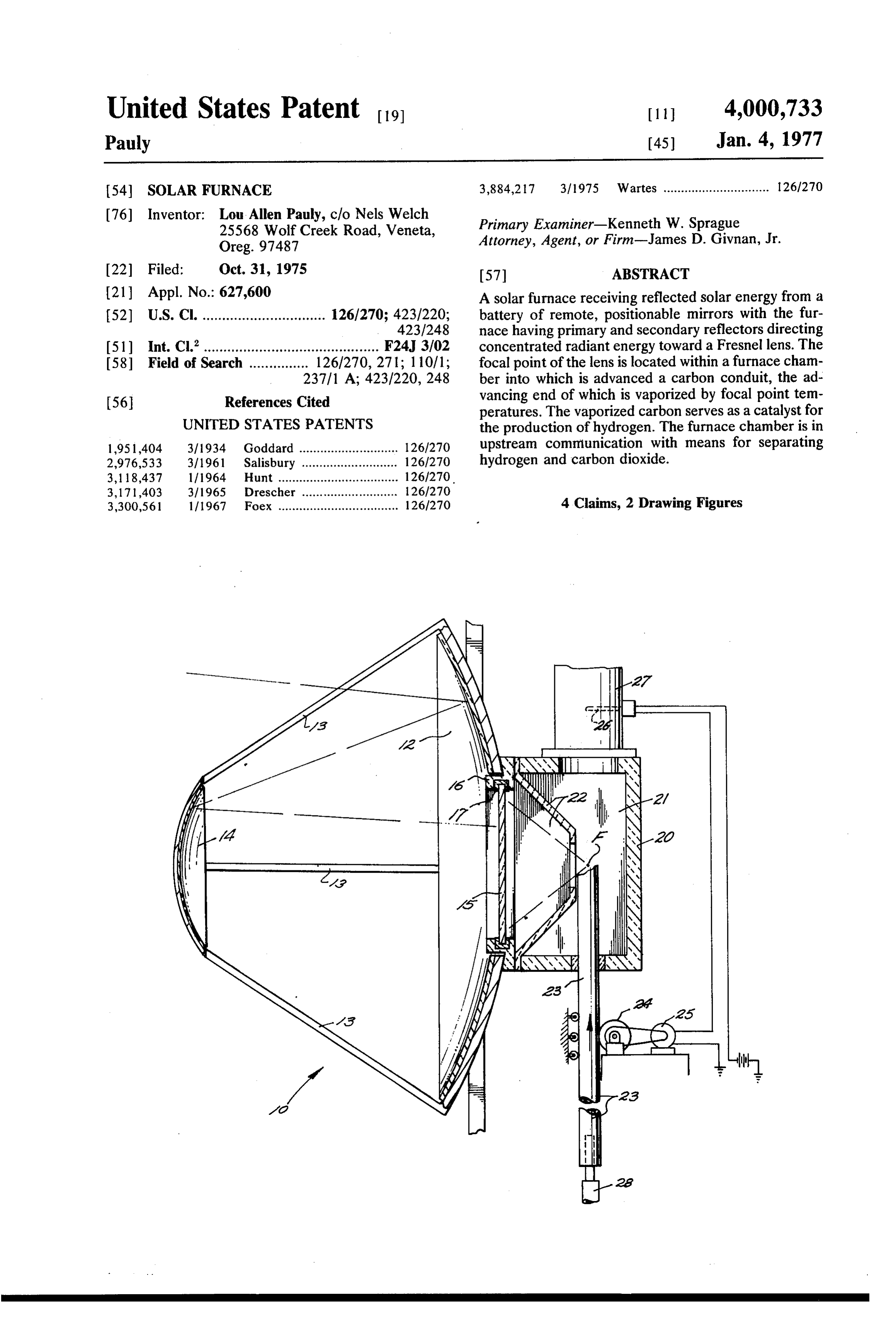
United States Patent to 11 4,000,733 Pauly 45) Jan. 4, 1977 54). SOLAR FURNACE 3,884,217 3/1975 Wartes .............................. 1261270 76) Inventor: Lou Allen Pauly, c/o Nels Welch Primary Examiner-Kenneth W. Sprague 25568 Wolf Creek Road, Veneta, Attorney, Agent, or Firm-James D. Givnan, Jr.
22 Filed: Oct. 31, 1975 57 ABSTRACT (21) Appl. No.: 627,600 A solar furnace receiving reflected solar energy from a 52) U.S. C. ............................... 126/270; 423/220; battery of remote, positionable mirrors with the fur 423/248 nace having primary and secondary reflectors directing
I51) Int. Cl.’............................................ F24J 3/02 concentrated radiant energy toward a Fresnel lens. The 58 Field of Search ............... 126/270, 271; 110/1; focal point of the lens is located within a furnace cham 237/1 A; 423/220, 248 ber into which is advanced a carbon conduit, the ad 56 References Cited vancing end of which is vaporized by focal point tem peratures. The vaporized carbon serves as a catalyst for
UNITED STATES PATENTS the production of hydrogen. The furnace chamber is in 1951.404 3/1934 Goddard ............................ 126/270 upstream communication with means for separating 2,976,533 3/1961 Salisbury ...... ... 126/270 hydrogen and carbon dioxide. 3,118,437 1/1964 Hunt .................................. 126/270.
3,171,403 3/1965 Drescher ........................... 126/270 3,300,561 1/1967 Foex .................................. 126/270 4 Claims, 2 Drawing Figures
Page 2
Drawing sheet — no readable text.
Page 3
radiant energy is imparted to the primary reflector
SOLARFURNACE . .. from the multiple reflector units 1. . . .
In fixed relationship with the primary reflector by
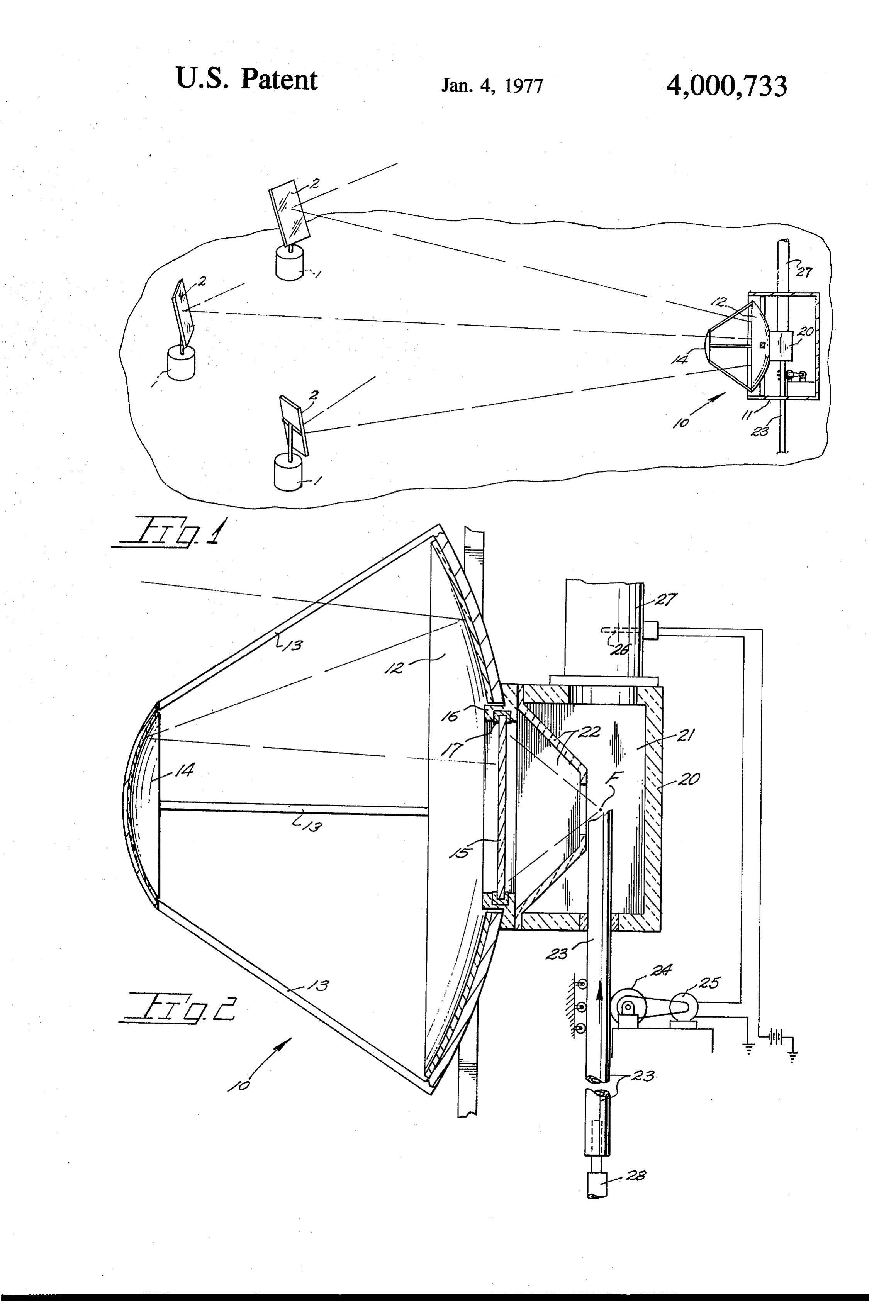
BACKGROUND OF THE INVENTION - means of suitable supports or struts 13 is a secondary The present invention relates generally, to furnaces 5 reflector 14 of lesser size but also of parabolic configu utilizing solar energy as a heat source and more partic ration with a reflective surface. Both of said primary ularly to such a furnace having multiple parabolic re and secondary reflectors have aligned axes. flectors and a Fresnel lens joined in a single mirror A Fresnel lens is indicated at 15 disposed normal to Structure. the above mentioned axes. The lens may be structurally Well known in solar energy utilization is the use of a O integrated with the primary reflector. A lens mount is multitude of mirrors remotely located from a furnace indicated at 16 which is conveniently supported by said with each positionable so as to track the apparent primary reflector and includes an insulative retainer 17 movement of the sun and reflect radiant energy within which the Fresnel lens is positioned. towards the furnace. Also known in the art is the use of An expansion chamber 21 is located rearwardly of parabolic mirrors and Fresnel mirrors to concentrate 15 the lens within an enclosure 20 also within which is radiant energy toward a heat transferring body of the located the focal point at F of lens 15. An apertured furnace. Typically the focal point of the converging partition at 22 permits unobstructed passage of the rays will lie in a plane common to a furnace wall or like converging focused rays while serving to protect the conductive structure whereat radiant energy is con lens.
verted to heat for transfer to a medium. Extending into the furnace is a movable conduit 23 SUMMARY OF THE INVENTION which is advanced into the furnace chamber by drive means at 24 so as to at all times retain an upper end of
The present invention is embodied within a solar conduit in close proximity to focal point F of the Fres furnace including opposing reflectors serving to direct nel lens. The conduit, being of carbon, vaporizes upon radiant energy toward a Fresnel lens of the furnace. 25 entering the focal area of lens 15. The reflectors of the present furnace receive radiant Friction drive means 24 includes a gearhead motor energy from a battery of mirrors each positionable and 25, the operation of which is controlled by a control remotely disposed from the furnace. The cooperating system including a sensor 26 located in a furnace outlet reflectors constituting part of the present invention are 27. Various other types of drive means may serve joined in a unitary furnace structure which additionally 30 equally well to advance conduit 23 into the furnace includes a Fresnel lens. The lens focal point is adjacent chamber.
the discharge end of a conduit and is adapted to carry The outer or lower end of conduit 23 is in communi a gaseous flow. Vaporization of the advancing conduit cation with a source of steam such as by a flexible end provides a catalyst for the production of hydrogen. conduit 28.
The conduit is adapted for progressive, axial movement 35 In operation, carbon conduit 23 through which steam into the furnace chamber. is routed is progressively advanced toward focal point F BRIEF DESCRIPTION OF THE DRAWING whereat concentrated radiant energy vaporizes the conduit for the formation of hydrogen and carbon diox
In the accompanying drawing, ide within furnace chamber 21. As hydrogen is highly FIG. 1 is a diagrammatic view of a furnace system for 40 useful when isolated, the combined flow of hydrogen the utilization of radiant energy, and and carbon dioxide is routed through separating means FIG. 2 is a vertical sectional view of a solar furnace such as water whereat carbon dioxide is removed from embodying the present invention removed from its the furnace outlet flow.
supporting enclosure. While I have shown but one embodiment of the in 45 vention it will be apparent to those skilled in the art
DETAILED DESCRIPTION OF THE PREFERRED
EMBODIMENT that the invention may be embodied still otherwise without departing from the spirit and scope of the in
With continuing attention to the accompanying vention.
drawing wherein applied reference numerals indicate Having thus described the invention what is desired parts similarly identified in the following description, 50 to be secured under a Letters Patent is: the reference numeral 1 indicates remote mirror units 1. In a system for concentrating radiant energy in each including a reflector panel 2 positionable in re cluding multiple positionable mirrors remotely located sponse to signals originating at a light sensing tracking from and reflecting radiant energy toward a solar fur device on each unit. The panels 2 may be said to track nace, the improvement embodied in a solar furnace, the apparent travel of the sun above the horizon so as 55 comprising to reflect radiant energy toward the present solar fur a primary reflector receiving radiant energy from nace. Within the state of the art are such reflector units said positionable mirrors, and therefore further details of same are dispensed a secondary reflector axially offset from said primary with. reflector redirecting radiant energy towards said A solar furnace embodying the present invention is 60 primary reflector, indicated generally at 10 and includes a housing 11 a Fresnel lens disposed normal to the aligned axes of serving to mount mirror components and to isolate said primary and secondary reflectors and receiv furnace components from ambient air. Preferably fur ing radiant energy from said secondary reflector, nace structure 10 is of stationary construction. and
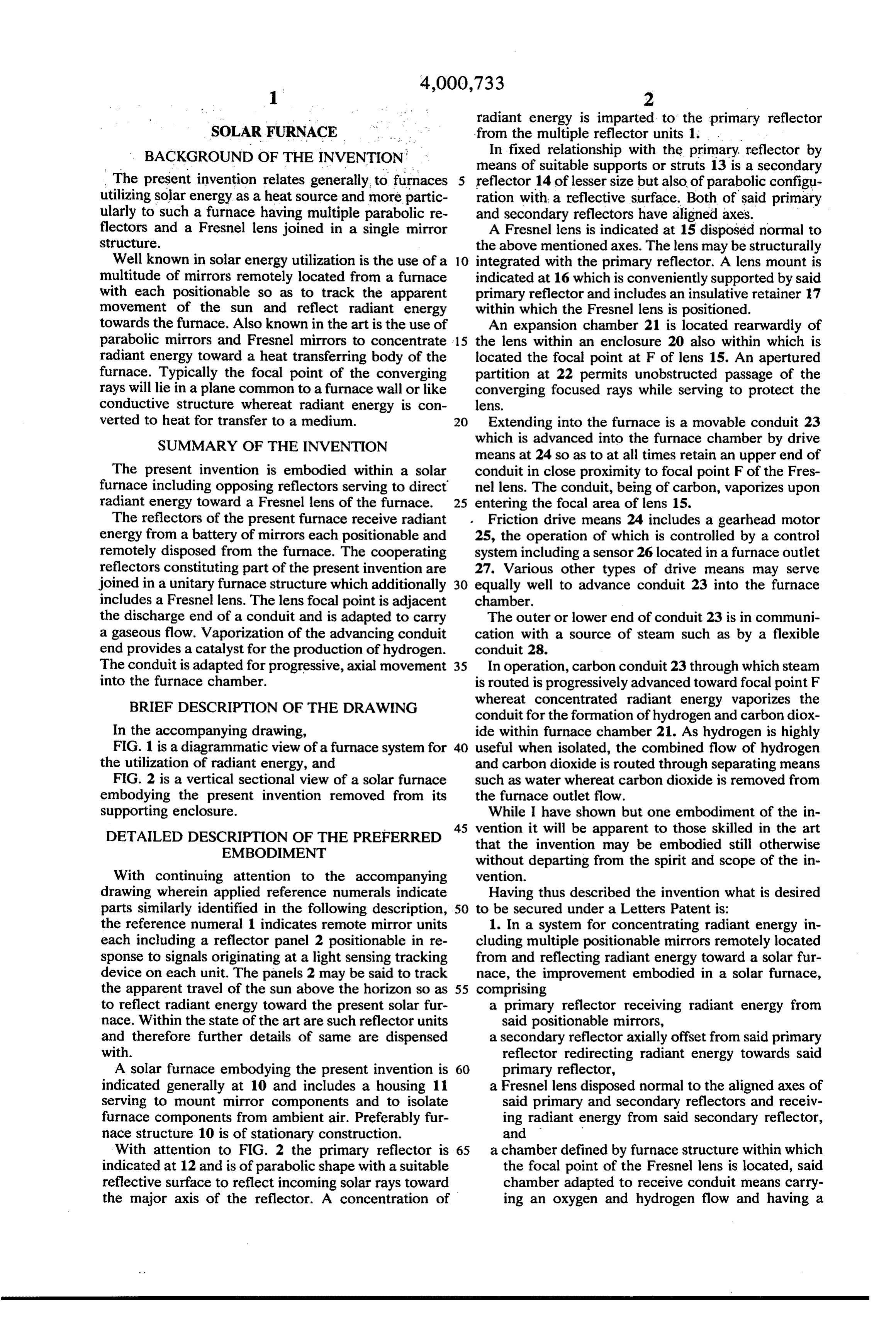
With attention to FIG. 2 the primary reflector is 65 a chamber defined by furnace structure within which indicated at 12 and is of parabolic shape with a suitable the focal point of the Fresnel lens is located, said reflective surface to reflect incoming solar rays toward chamber adapted to receive conduit means carry the major axis of the reflector. A concentration of ing an oxygen and hydrogen flow and having a
Page 4
discharge end in close proximity to the focal point 3. The furnace improvement claimed in claim 2 addi of the Fresnel lens whereby the conduit and con- tionally including means for progressively advancing said conduit into the furnace chamber.
duit e flow are heated by concentrated radiant en 4. The furnace improvement claimed in claim 3 gy. 5 wherein said conduit means serves to convey a steam 2. The furnace improvement claimed in claim 1 flow into said furnace chamber for the production of wherein said conduit is of carbon vaporized by concen- hydrogen and carbon dioxide in the furnace chamber. trated radiant energy. sk k k k sk
Provenance
- Collection
- Cited prior art
- Original PDF
- patentimages.storage.googleapis.com →
- Filed
- 1975-10-31
- Pages
- 4
- Method
- pdftotext (the PDF's own text layer) + pdftoppm 300dpi page scans
- Source
- Google Patents bibliographic record
- Granted
- 1977-01-04
- Inventors
- Lou Allen Pauly
- Transcribed from
- patentimages.storage.googleapis.com →