patent · US4064865
Solar actuated boiler and appurtenances
27 December 1977
Page 1 — bibliographic record
United States Patent 19 11) 4,064,865 Depew 45) Dec. 27, 1977
54 SOLARACTUATED BOLER AND
FOREIGN PATENT DOCUMENTS
APPURTENANCES
131,069 1/1949 Australia .............................. 126/270 76 Inventor: Walter L. Depew, 3111 W. 54th Ave., 555,420 3/1923 France ................................. 126/270 Denver, Colo. 80221 18,998 of 1913 United Kingdom ................. 126/271 21 Appl. No.: 572,083 Prinary Examiner-Kenneth W. Sprague 22 Filed: Apr. 28, 1975 Assistant Examiner-James C. Yeung 51) Int. Cl? ................................................. F24J 3/02 Attorney, Agent, or Firm-O'Rourke & Harris 52 U.S. C. .................................... 126/271; 350/292; 57 ABSTRACT
58) Field of Search ............... 126/270, 271; 237/1 A; A solar actuated boiler which receives the incident rays 350/292, 293, 299,294 of the sun, magnifying them and concentrating them at precise multiple points. This concentration results in an 56) References Cited aqueous solution, under pressure, being heated to tem
1,130,871 3/1935 Willsie .................................. 126/271 from this solution will then be convected through a 1,658,455 2/1928 Metzech et al. ..................... 126/271 system of piping, deposited and stored in the systems 1,855,815 4/1932. Abbot ................................... 126/271 heat storage vault. This stored heat is then convected 2,382,722 8/1945 Kezer ................................... 26/271 through a companion system of piping for the purpose 2,693,939 11/1956 Marchant et al. ................... 126/271 of, but not limited to, such uses as heating, domestic hot 2,920,710 /1960 Howard ............................... 126/270 water, air-conditioning and electrical energy. 2,969,918 1/1961 Phelps .................................. 126/270 3,401,682 9/1968 Jakob ................................... 26/400 3,822,692 7/1974 Demarest ............................. 126/27 10 Claims, 17 Drawing Figures
Page 2
Drawing sheet — no readable text.
Page 3
Drawing sheet — no readable text.
Page 4
Drawing sheet — no readable text.
Page 5
Drawing sheet — no readable text.
Page 6
understood by reference to the description taken in
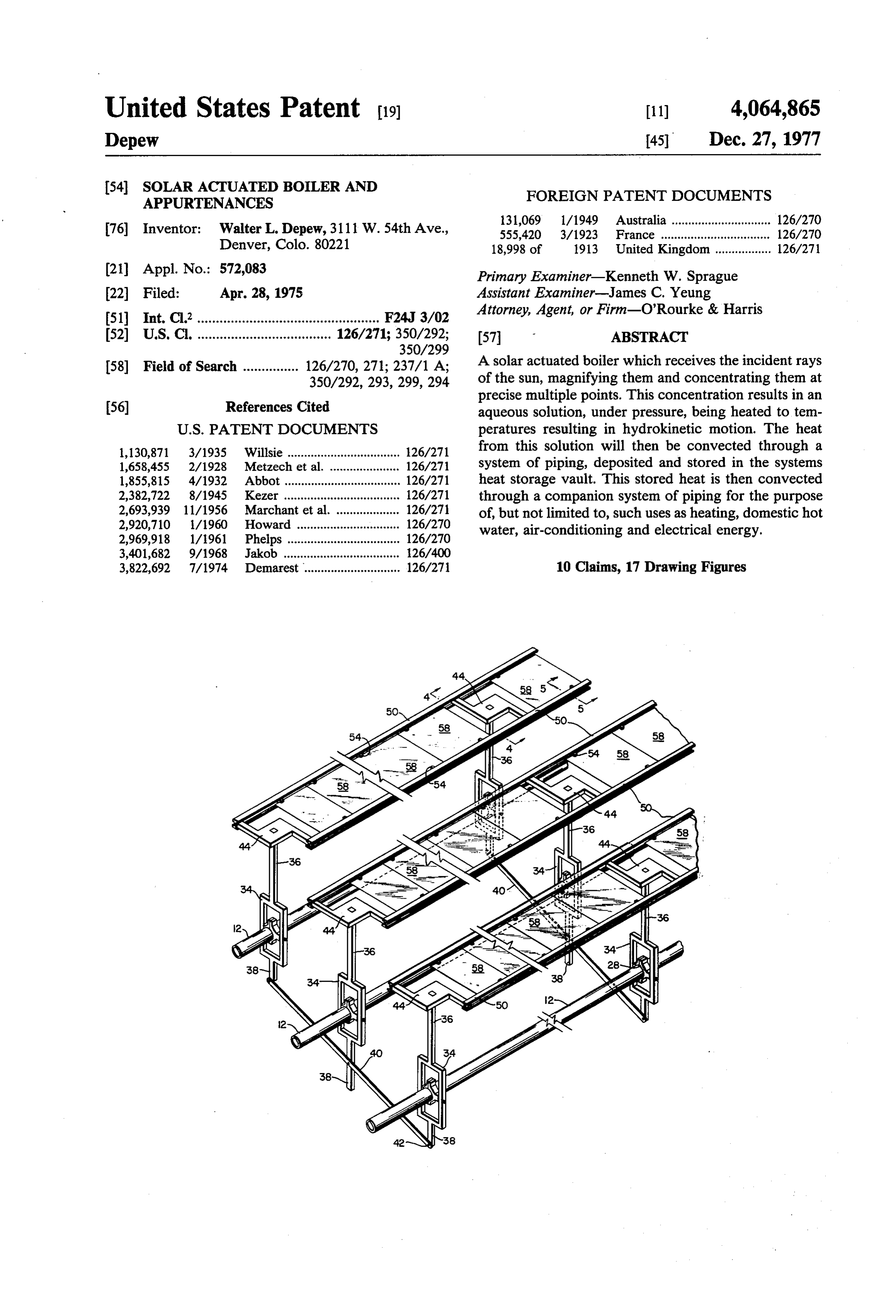
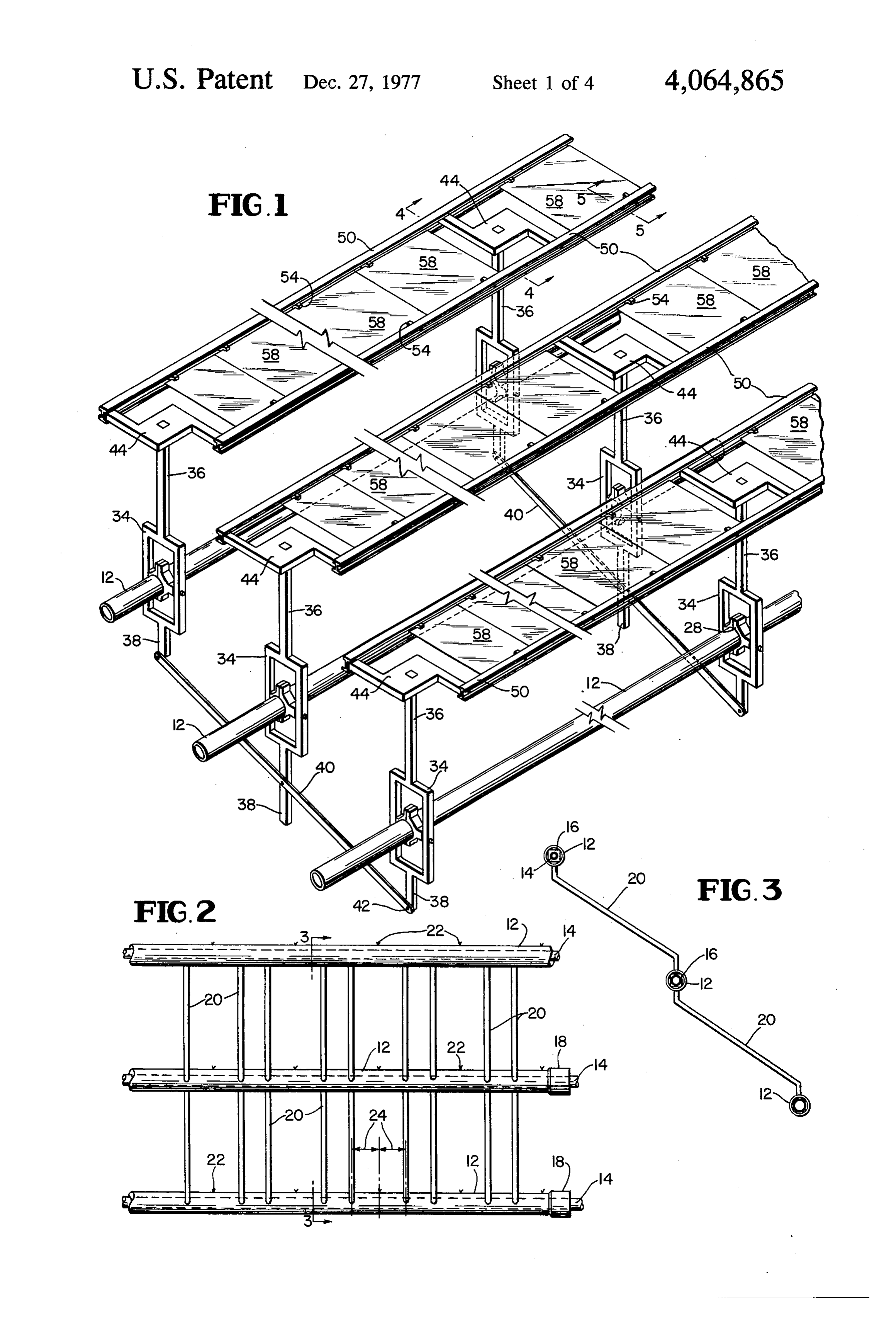
SOLARACTUATED BOLER AND conjunction with the accompanying drawings in which: APPURTENANCES FIG. 1 is a perspective view of the boiler assembly; GENERAL DESCRIPTION OF THE INVENTION 5 core FIG. 2 is a front elevation of a header section and piping;
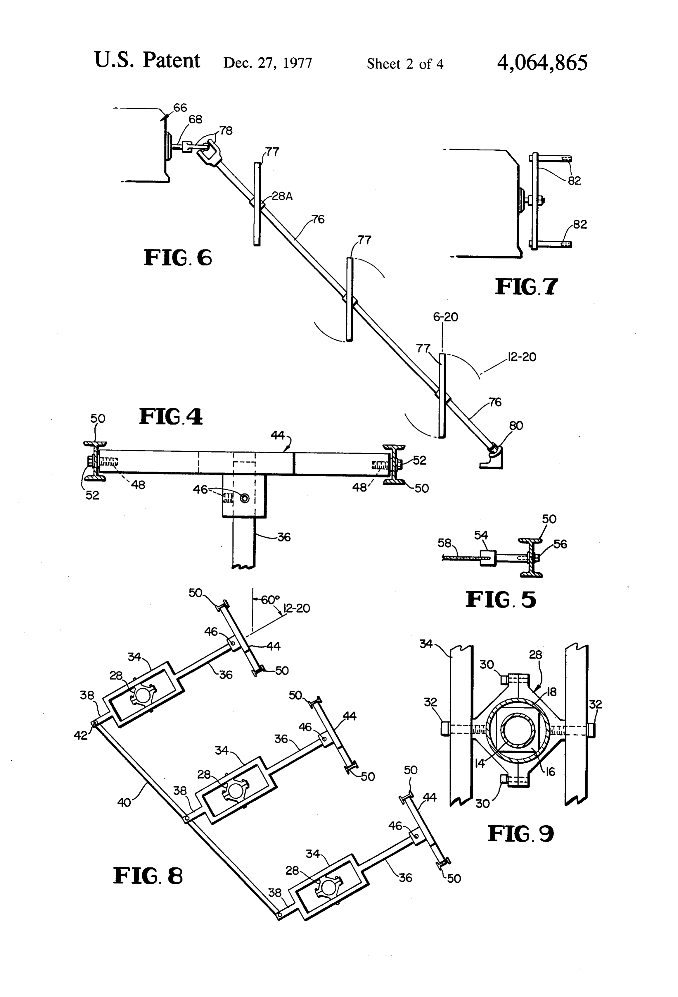
This invention relates to a solar actuated boiler and FIG. 3 is a cross-section taken along line 3-3 of FIG. more particularly to a solar actuated boiler which mag 2 showing core piping connecting header; nifies rays of solar energy to precise multiple spots on FIG. 4 is a cross-section taken along lines 4-4 of FIG. pre-fabricated manifolds of piping. These manifold 1 showing, paddle and focal adjuster end view of rack pipes are not limited in number and may be assembled in 10 and rails with connectors;
any multiple of rows. The header pipe portion of said FIG. 5 is a cross-section taken along lines 5-5 of FIG. manifolds have attached to them, power operated focal 1 showing lens swivel connected to rack and rail; oscillators. Operating in complete harmony and unison, FIG. 6 is a schematic view showing multiple actuator the focal oscillators maintained the magnified rays of assembly;
solar energy on precise points of the manifold headers 15 FIG. 7 is a schematic view of inclination and declina not only during all sunlight hours (A.M. to P.M.) but tion actuator;
additionally they follow precisely the suns path in its' FIG. 8 is a schematic view showing the focal oscilla inclination (winter and summer) and declination (sum tor at 12-20 declination;
mer to winter) continuously. The solar actuated boiler FIG. 9 is a fragmentary view of the bearing assembly, and power operated oscillators, when mounted on the 20 boss assembly, heat sink pipe, spacer, coupler, axle and bearing and axle assembly and properly assembled with spread of the oscillator;
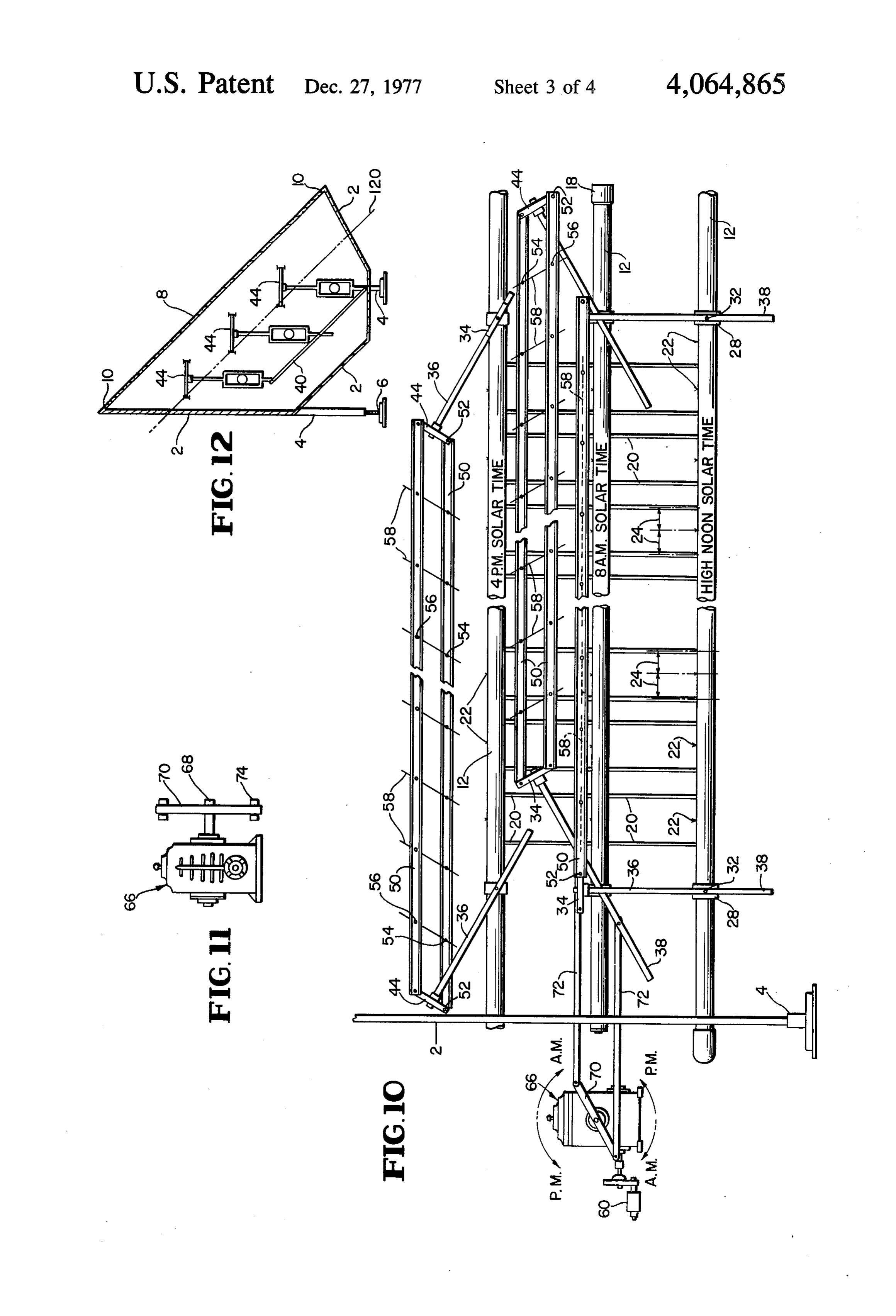
the paddle and focal adjusters, lens rack and rail, con FIG. 10 is a front view of the elevation of the boiler nectors, swivels and magnifying lenses, operate in com assembly showing:
plete timed unison. The combination of these factors a. Lens and focal oscillator at high noon solar time; result in the intense heating of the boiler manifolds 25 b. Power operator, power unit transmission, actuator which contain an aqueous solution. Such heating of said crank, connecting arms to focal oscillators, lens solutions bring about hydrokinetic motion. The mani rack and rail and lens tilt to 8 a.m. solar time; folds connect through the expansion tank directly into c. Lens and focal oscillator at 4 p.m. solar time; the serpantine coils of a heat storage vault. With the FIG. 11 is a schematic view of the power unit trans existance of this concentrated solar energy and the re 30 mission;
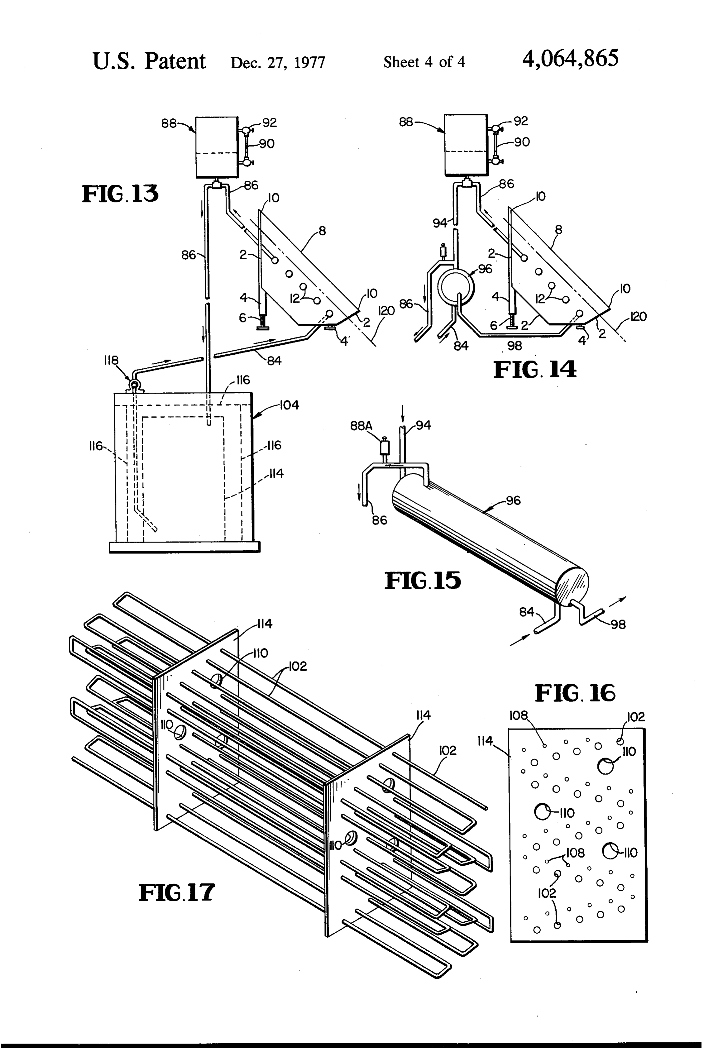
sulting hydrokinetic motion the system, depending on FIG. 12 is a schematic view of the boiler receiver topography will continually circulate. Alternate piping, trough with maximum roof insert line or shadow line; going from the expansion tank to a heat exchanger, FIG. 13 is a schematic view of the piping diagram would mean that a forced flow circulator would be and maximum insert or shadow line; incorporated from the heat storage vault. 35 FIG. 14 is a schematic view of alternate piping dia The insert of the heat storage vault consist of prop gram and maximum insert or shadow line; erly engineered and ported pipe supports and spacers. FIG. 15 is a schematic view of heat exchanger; The purposes of these supports and spacers are equal FIG. 16 is an elevation of pipe support and spacer, distribution of heat, ease of assembly and erection, and ported;
simplified mass production. The insert is ported to re FIG. 17 is a perspective view of boiler heated coil. ceive no less than, but not limited to, 3 compatable Referring now to the drawings, the header pipes 12 serpentined coils. One of the coils is connected continu with their core piping 20 are, for purposes of mass pro ously from the expansion tank and returning to the solar duction, made into sections of multiple headers 12. A boiler. This coil is used for the convection of the aque boiler receiver 2 is properly installed and leveled from ous solution and its accumulated heat and the deposit 45 true north. At this time the lattitude pitch adjuster 6, a and storage of that heat within the internal medium of part of the support 4 and the boiler receiver 2, is ad the heat storage vault. The second of these serpentine justed to the installed units lattitude. The header pipes coils is utilized for the purpose of convecting the Equiv 12 are placed into the boiler receiver 2 and assembled alent Direct Radiation (E.D.R.s) to a structure, it is not by first inserting the loose focal oscillator 34 on the however limited to a structure. The third coil men 50 open spigot end of the header pipes 12 and then joining tioned would supply domestic hot water, air-condition the header pipes 12 together by means of the coupler 18. ing, snow melt or any feasible, assigned function. This Next the bearing assembly 28 is cast into two parts insert is placed within a prepared container sufficient to which are then placed center on coupler 18 and joined insulate and protect both the insert with coils and the by assembly boss 30. The focal oscillator 34 is slipped heat storage medium. 55 into the center position of the bearing assembly 28 and A general objective of the subject invention is a sub joined to the bearing assembly 28 by axle 32. In the stantial reduction in the use of existing fossil fuels. This above procedure there is placed on a second pipe, hav would be accomplished by no longer requiring those ing a dual function of both support and acting as a heat fuels in either their present or projected quantities. sink 14. Along with support spacer 16 and header piping Another object of the subject invention is a reduc 60 12, heat sink 14 extends through the end plates of the tion, in direct proportion to its' use, of combustible fuel boiler receiver 2. In schematic piping diagram, 84 is pollutients. joined to the header pipes 12 at the lowest point and A still further object of the subject invention is a discharge piping 86 is joined to the header pipes 12 at substantial monitary savings to the public. the boilers highest point. In schematic alternate piping The noval features which I believe to be characteris 65 diagram, 98 is joined to the header pipes 12 at the lowest tic of my invention are set forth with particularity in the point and discharge piping 86 is joined to the header appended claims. My invention itself, however, both as pipes 12 at the boilers highest point. Now the actuator to its organization and method of operation, may be best connecting arms 72 are connected to the focal oscillator
Page 7
34 and are extended through one end of the boiler re 2. A solar boiler as set forth in claim 1 in which each ceiver 2. The actuator connecting arms 72 are joined to focus point for each lense is spaced along the header the actuator crank 70 which has been previously assem pipe relative to other such focus points, and the tracking bled to the power transmission unit 66 and power opera means is adapted to move each converging lense sub tor 60. When, because of header pipe size and number, stantially through an arc centered on the fixed image it becomes necessary to utalize a combination of actua focus point of the corresponding lense on the header tors, FIG. 6 best illustrates this solution. The power unit pipe, whereby the focus point of each lense remains in a transmission 66, after being repositioned, is fitted on the substantially fixed position on the header pipe. shaft 68, with a universal joint 78. This combination tracking3. A solar boiler as set forth in claim 1 in which the drives a splined shaft 76 supported at one end by a 10 system comprises at least two parallel rails pillow block 80. A bearing assembly 28A with milling supporting the plurality of converging lenses with each to match the splined shaft 76 is attached to splined shaft lense being supported at one pivot point on each rail, 76. The #77 is simply a focal oscillator 34 with focal the pivot points connecting each lense being offset in stem 36 and focal oscillator tail 38 removed. Further, opposite directions from the center of the lense, a pair of pivot members attached to the rails at pivot points
FIG. 7 shows power unit transmission 66 with inclina 15 spaced tion and declination arms 82. Now to continue with similarly to the pivot points attaching each lense assembly. The lens rack and rail 50 are connected to to the rails, an arm member extending perpendicularly paddle and focal adjuster 44 by means of mounting from each such pivot member and the arm member shoulder screw 52. The magnifying lenses 58 are placed further being pivoted around an axis substantially paral into the lens swivel 54 and attached to the lens rack and lel to the plane in which the rails lie, a clockwork mech rail 50 by mounting shoulder screw 52. When assembly anism and means for orienting the arms in response to of lenses 58, lens rack and rail 50, with lens swivels 54 movement of the clockwork mechanism connected to are completely connected to the paddle and focal ad the clockwork mechanism, whereby, the arms may be justers 44 this assembly is placed atop the focal oscilla constantly oriented towards the solar body and, accord tor stem, 36, adjusted and set to the structure focal 25 ingly, the lenses supported between the rails will simi length of the lenses by set screws 46. The focal oscilla larly be oriented towards the solar body. tor connecting rod 40 is then attached to tail 38 of the 4. A solar boiler as set forth in claim 3 in which the focal oscillator 34 by the machined shoulder bolt 42. lenses and supporting rails are also rotatable around an The power to the actuator 60 is wired and the timing is axis perpendicular to the axis around which the member tested at this point of installation. The safety plate glass 30 is rotatable, whereby, the angle of inclination of the cover 8 is then placed and sealed 10 to the boiler re lenses may be adjusted.
ceiver 2. Depending on topography and desirability, a 5. A solar boiler as set forth in claim 4 in which the heat storage vault 104 is prepared on the site of installa axis around which the angle of inclination is adjusted is tion. Pipe support and spacers 114, boiler heated coil substantially concentric with the header pipe. 102, radiant coils 108, and domestic coil 110, all pre 6. A solar boiler as set forth in claim 3 in which the assembled, are placed within the heat storage vault 104. 35 axis around which the arms are rotatable extend perpen The piping 86 connecting with 102, the circulator 118 dicularly through the header pipe.
connecting to 84 complete the piping circuit. The sys 7. A solar boiler as set forth in claim 3 in which a tem is filled with its aqueous solution and tested to 300 plurality of pairs of parallel rails supporting converging lbs. p.s. i. After connecting serpentine coil 108 to struc lenses are provided with similarly spaced pivot mem ture and connecting domestic hot water coil 110 to bers and arms, with the arms being interconnected by a fixtures the heat storage vault 104 is filled with the heat pivotally attached linkage member to concurrently storage medium, insulated and covered. drive all of the arms.
While I have shown and described specific embodi 8. A solar boiler as set forth in claim 1 which further ments of my invention, it will, of course, be understood 45 includes a serpentine pipe, an insulated vault, and a heat that various modifications and alternative constructions storage medium, and in which the header pipe is con may be made without departing from the true spirit and nected to a serpentine pipe housed in an insulated vault, scope of this invention. For this reason I intend, there the serpentine pipe being immersed in a heat storage fore, by the appended claims to cover all such arrange medium, whereby heat from the serpentine pipe may be ments falling within the true spirit and scope of these conducted to the heat storage medium within the vault. claims. 9. A solar boiler as set forth in claim 8 in which at I claim: least two additional serpentine pipes independent from 1. A solar boiler comprising: and each substantially equally spaced from the first at least one elongated header pipe, a plurality of serpentine pipe are included in the vault, whereby heat ganged, discrete, movable mounted converging stored in the storage medium may be conducted from lenses adapted to provide a point image positioned 55 the vault through the additional serpentine pipes. adjacent to but spaced from the header pipe with 10. A method of collecting solar energy comprising: each lense focused thereon to produce an individ focusing a group of ganged concentrating lenses on at ual and discrete focused point image on the header least one header pipe to define a plurality of image pipe corresponding to each lense, and tracking points, automatically moving the lenses synchro means connected to each lense to automatically nously along the azimuth to track a solar body as and synchronously move the lenses through the the solar body moves relative to the header pipe, azimuth to follow a solar body and maintain the maintaining a substantially constant distance sub focused, concentrated point image of the solar stantially equal to the focal length of the lense body on the header pipe, whereby the boiler may between each lense and the image point of the lense be maintained in an advantageous configuration for 65 on the header pipe, and maintaining the image the collection of solar energy on the header pipe by point on the header pipe in a substantially fixed the lenses as the relative position of the solar body position as the lense moves.
and the boiler header pipe change.
Provenance
- Collection
- Cited prior art
- Original PDF
- patentimages.storage.googleapis.com →
- Filed
- 1975-04-28
- Pages
- 7
- Method
- pdftotext (the PDF's own text layer) + pdftoppm 300dpi page scans
- Source
- Google Patents bibliographic record
- Granted
- 1977-12-27
- Inventors
- Walter L. Depew
- Transcribed from
- patentimages.storage.googleapis.com →