patent · US4139286
Apparatus for concentrating solar energy
13 February 1979
Page 1 — bibliographic record
United State 4,139,286 Hein et al. irl Feb. 13, 1979
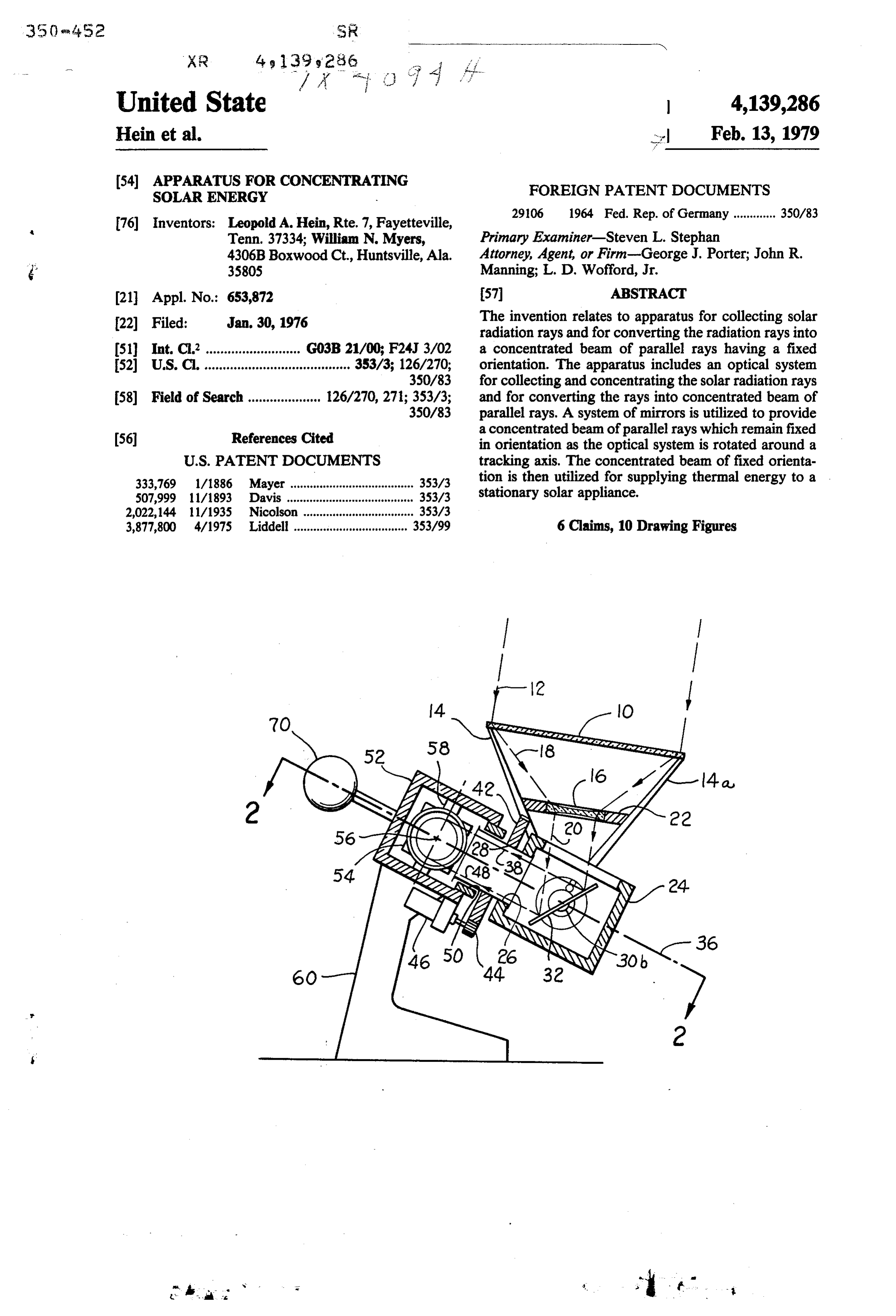
(54) SEAR SE CONCE TING FOREIGN PATENT DOCUMENTS 76 Inventors: Leopold A. Hein, Rte. 7, Fayetteville, 2906 1964 Fed. Rep. of Germany ............. 350/83 Tenn. 37334; William N. Myers, Primary Examiner-Steven L. Stephan 4306B Boxwood Ct., Huntsville, Ala. Attorney, Agent, or Firm--George J. Porter; John R. 3.5805 Manning; L. D. Wofford, Jr.
(21) Appl. No.: 653,872 57 ABSTRACT The invention relates to apparatus for collecting solar 22 Filed: Jan. 30, 1976 radiation rays and for converting the radiation rays into 51) Int. C.’.......................... G03B 21/00; F24J 3/02 a concentrated beam of parallel rays having a fixed 52 U.S. C. ........................................ 353/3; 126/270; orientation. The apparatus includes an optical system 350/83 for collecting and concentrating the solar radiation rays 58) Field of Search .................... 126/270, 271; 353/3; and for converting the rays into concentrated beam of 350/83 parallel rays. A system of mirrors is utilized to provide a concentrated beam of parallel rays which remain fixed (56 References Cited in orientation as the optical system is rotated around a
333,769 1/1886 Mayer. is tion is then utilized for supplying thermal energy to a 507,999 11/1893 Davis .......... 3533 stationary solar appliance.
2,022,144 11/1935 Nicolson ................................333/3 3,877,800 4/1975 Liddell ................................... 353/99 6 Claims, 10 Drawing Figures
. . w s f i.
Page 2
Drawing sheet — no readable text.
Page 3
Drawing sheet — no readable text.
Page 4
Drawing sheet — no readable text.
Page 5
ing provided in the wall or roof of a residential structure
APPARATUS FOR CONCENTRATING SOLAR and the like.
ENERGY Yet another important object of the present invention
ORIGIN OF THE INVENTION
is to provide apparatus for collecting solar radiation and for converting the radiation into a concentrated beam
The invention described herein was made by employ having a fixed orientation which remains fixed while the ees of the United States Government and may be manu optical system of the apparatus tracks the sun about a factured and used by or for the Government for govern plurality of axes.
mental purposes without the payment of any royalties These and other objects and advantages of the pres thereon or therefor. 10 ent invention will become apparent upon reference to the following specification, attendant claims and draw
BACKGROUND OF THE INVENTION 1ngs.
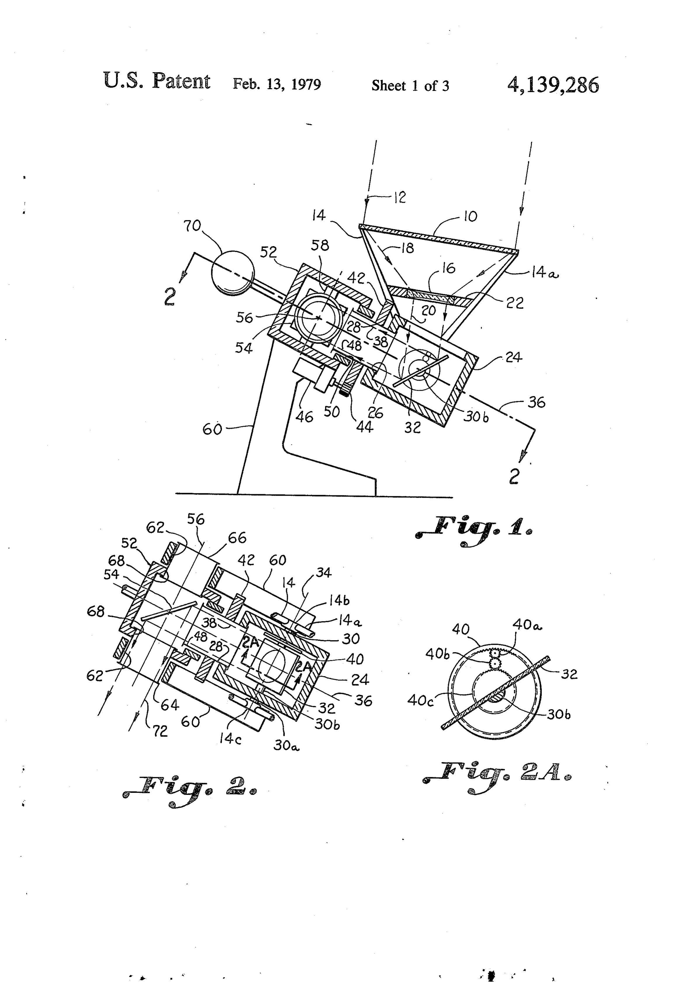
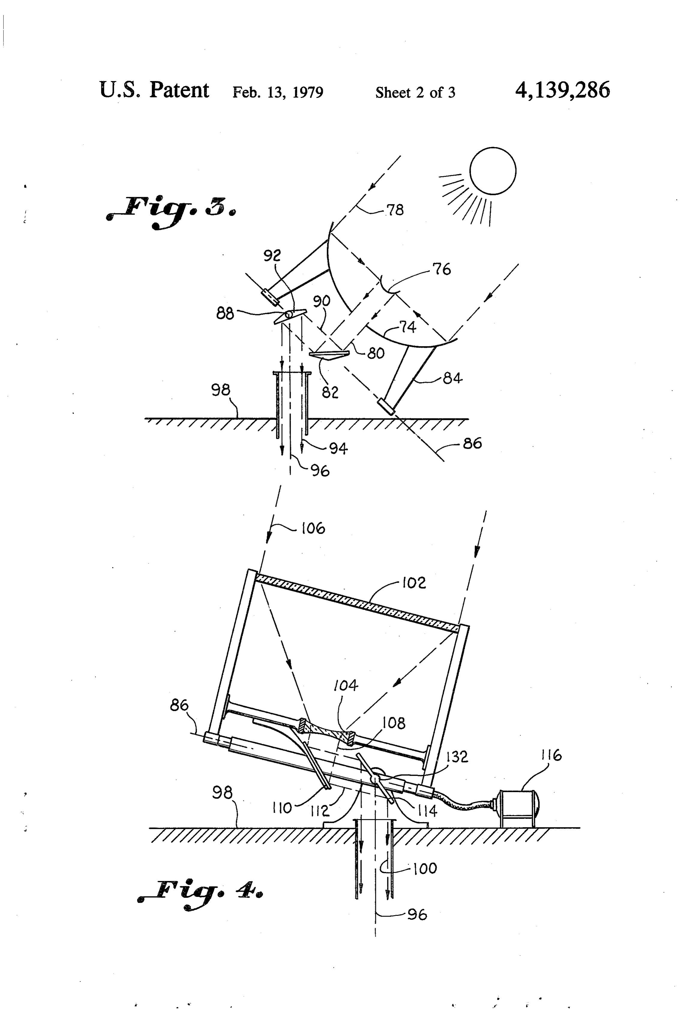
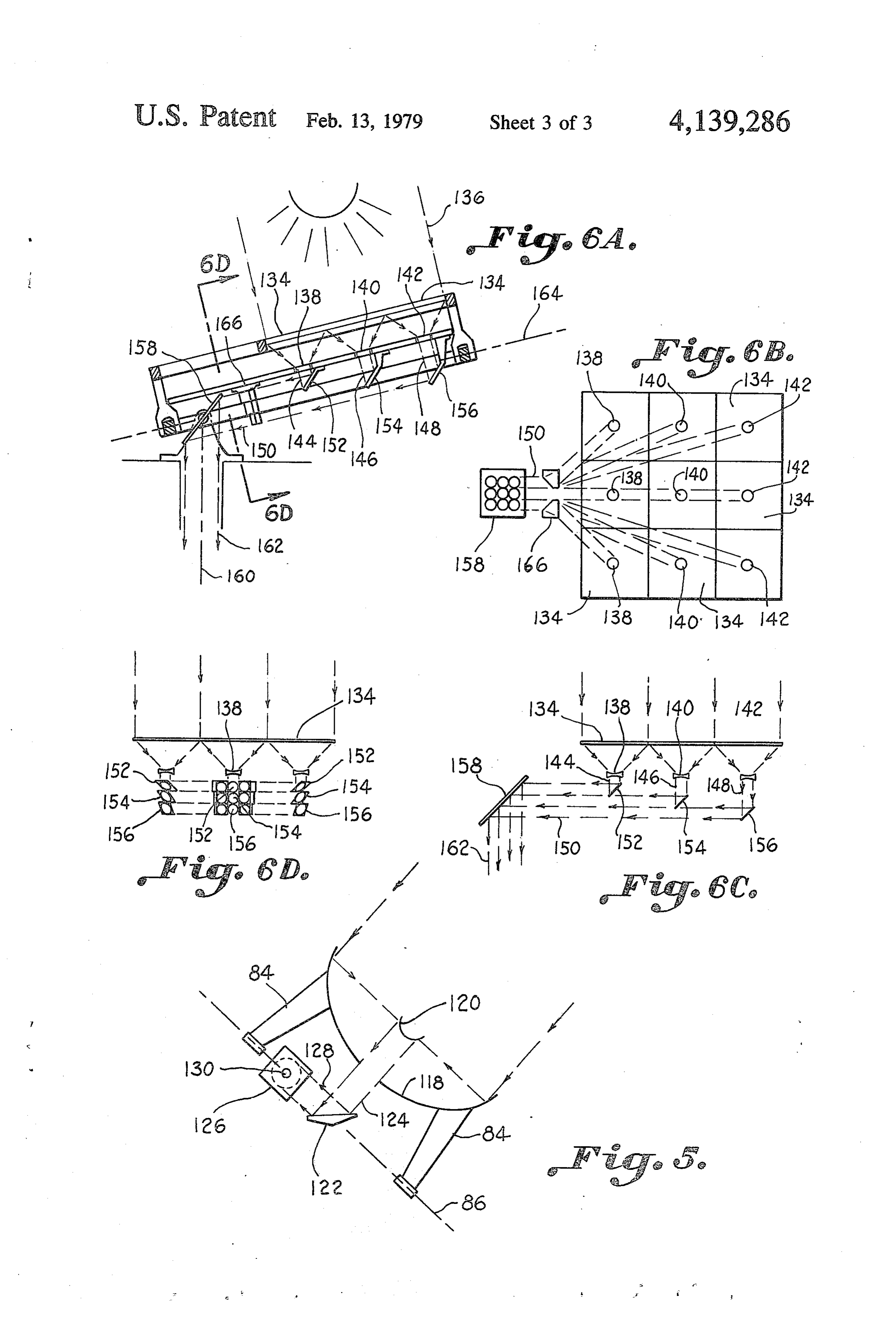
Utilization of tracking apparatus, including rotation BRIEF DESCRIPTION OF THE DRAWING of mirrors or reflectors about two axes, for concentrat ing solar energy is known in the art such as shown in 15 FIG. 1 is a sectional side elevational view of an appa U.S. Letters Pat. No. 3,713,727. Concentrated solar ratus for collecting solar radiation rays and converting radiation rays have also been utilized in heating devices the radiation into a concentrated beam of fixed orienta commonly referred to as heliostat devices having a lens tion, constructed in accordance with the present inven system for supplying a concentrated beam of energy to tion, an associated solar heater. However, in such prior FIG. 2 is a top plan sectional view taken along section known devices, the solar heater is required to move line 2-2 of FIG. 1, with the lens system as the path of the sun is tracked FIG. 2A is an enlarged sectional view taken along during the day. This presents a problem when it is de section line 2A-2A of FIG. 2, FIG. 3 is a schematic side elevational view of an sired to use the concentrated beam for supplying ther alternate embodiment of apparatus for collecting and mal energy to an associated solar stove or furnace 25 concentrating solar radiation constructed in accordance which is stationary, such as within the interior space of a home. Since the concentrated beam of solar radiation with the present invention, in such prior devices moves with the lens system, such an FIG. 4 is a sectional side elevational view illustrating alternate embodiment of apparatus for collecting and is impractical for use in residential buildings for supply 30 concentrating solar radiation into a fixed vertical beam, ing heat to cooking or heating appliances. constructed in accordance with the present invention, SUMMARY OF THE INVENTION FIG. 5 is a schematic side elevational view illustrat Apparatus is provided for converting concentrated ing an alternate embodiment of apparatus for collecting and concentrating solar radiation into a fixed horizontal solar radiation into a beam of fixed orientation for sup 35 plying thermal energy to an associated stationary solar beam, constructed in accordance with the present in appliance. The apparatus comprises an optical system vention, FIG. 6A is a sectional side elevational view illustrat having a primary lens assembly and a secondary lens ing an alternate embodiment of apparatus for collecting assembly for collecting and concentrating solar radia and concentrating solar radiation into a fixed vertical tion rays and converting the radiation rays into a beam beam constructed in accordance with the present inven of parallel rays of radiation. Tracking means is provided tion, for rotating the optical system about a tracking axis to FIG. 6B is a top plan view of the apparatus illustrated follow the path of the sun during the day. A first mirror in FIG. 6A, member receives the beam of parallel rays and reflects a FIG. 6C is a schematic side elevational view of the first beam along the tracking axis. The first beam rotates 45 apparatus of 6A with parts omitted for purposes of about the tracking axis as the optical system tracks the clarity, and sun. A second mirror member receives the first beam FIG. 6D is a sectional view taken along line 6D-6D from said first mirror member and reflects a second of FIG. 6A.
beam along a latitude adjustment axis perpendicular to DESCRIPTION OF A PREFERRED the tracking axis. Thus, the second beam remains fixed 50 EMBODIMENT along the latitude adjustment axis as the optical system rotates about the daily and seasonal tracking axes pro The drawings illustrate apparatus for collecting solar viding a beam of fixed orientation to be directed to the radiation rays and for converting the radiation rays into solar appliance for supplying thermal energy thereto. a concentrated beam of parallel rays having a fixed Accordingly, an important object of the present in 55 orientation. The apparatus may be utilized for supplying vention is to provide apparatus for producing a concen concentrated thermal energy along a fixed axis to a trated beam of solar radiation having a fixed orientation. stationary solar appliance such as an oven or heater Another important object of the present invention is located in a residential building and the like. to provide an optical system which will produce a fixed The apparatus includes an optical system having a concentrated beam of solar radiation and is capable of 60 primary lens assembly 10 for receiving oncoming solar producing high temperatures for utilization in associ radiation rays 12 which is suitably mounted on a pair of ated solar appliances permanently mounted within resi upwardly extending standards 14 and 14a. The optical dential structures and the like. system further includes a secondary lens assembly 16 Still another important object of the present inven which receives radiation rays 18 collected by the pri tion is to provide apparatus for collecting solar radia 65 mary lens 10 for converting the rays 18 into a concen tion rays and converting the radiation into a concen trated beam of parallel rays 20. The secondary lens trated beam having a fixed orientation along either a assembly 16 is carried by a bracket 22 supported by horizontal or vertical axis for passage through an open standards 14 and 14a. A housing 24 has an opening 26
Page 6
formed in the sidewall thereof. A radiation pipe 28 is A counterweight member 70 is provided to facilitate affixed within the opening 26 of the housing 24 for rotation of the housing 52 and, thus, the mirror member supporting the housing 24 thereon. The standards 14 54 about the axis 56 which is a latitude adjustment axis and 14a are suitably affixed to shaft members 30 and 30a adjusted to compensate for various latitudes in which extending from the housing 24. the system may be used. The optical system including The beam of parallel rays 20 concentrated by the lenses 10 and 16 and the first mirror member 32 may be secondary lens 16 impinge on a first mirror member 32 manually rotated about the axis 56 to compensate for which is carried in the housing 24 on a shaft member various latitudes.
30b, Shaft member 30b is concentric with seasonal axis The second mirror member 54 reflects and directs a 34. The mirror member 32 has an angular inclination to 10 second concentrated beam of parallel rays 72 along the the oncoming rays 20. The mirror member 32 reflects latitude adjustment axis 56 to provide a concentrated the concentrated beam 20 along an axis 36 which is a beam of fixed orientation which may be supplied to an tracking axis of the optical system providing a first associated, stationary appliance located in a residential concentrated beam 38 of parallel rays directed along the structure and the like. The concentrated beam 72 re tracking axis 36. The shaft member 30b is affixed to 15 mains fixed in its direction while the optical system, shaft members 30 and 30a through gears 40, 40a, 40b, including lenses 10 and 16, and the first mirror member and 40c. 32 are rotated about the daily tracking axis 36 and the The tracking axis 36 is a daily tracking axis to com latitude adjustment axis 56. The concentrated beam 72 pensate for the changes in the position of the sun during also remains fixed in its direction while the optical sys the daylight hours. A gear 42 is adapted to be received 20 tem, including lenses 10 and 16, is rotated about the over the radiation pipe 28 for affixation thereto. The seasonal tracking axis 34. The first concentrated beam teeth of gear 42 mesh with a gear 44 carried on the 38 will rotate concentrically about the tracking axis 36 output drive shaft of a daily tracking motor 46. One end while the second concentrated beam 72 will rotate con 48 of the radiation pipe portion 28 is suitably journaled centrically about the latitude adjustment axis 56 as does in an opening 50 formed in an end wall of a housing 52 25 mirror member 54, but without a change in the direc for rotation therein. tion of the concentrated beam 72. Thus, the tracking motor 46 rotates the radiation pipe The use of the advantageous mirror system of the 28, the entire optical system including lenses 10 and 16, apparatus constructed in accordance with the present the housing 24 affixed to the radiation pipe 28, and the invention removes the need for mirror angulation dur mirror member 32 carried within the housing to follow 30 the path of the sun during the daylight hours. The con ing the day. This is accomplished by placing the mirror centrated beam 38 which is directed through the radia members 32 and 54 as illustrated in FIGS. 1 and 2 such tion pipe 28 rotates concentrically about the tracking that the angle ofofreflection that the angles reflection are constant. It can be seen between the reflective beams axis 36, but does not change its direction.
A second mirror member 54 receives the concen 35 20 and 38 will remain constant throughout the day trated beam 38 from the first mirror member 32 and although the optical system is rotated about the tracking reflects and redirects the concentrated beam along an axis. trated
The mirror member 32 reflects the second concen beam 38 concentric with the tracking axis, thus axis 56 which is perpendicular to the tracking axis 36. the beam remains stationary, only rotating concentric The mirror 54 is carried in the housing 52 on a trans with the tracking axis 36 as the optical system, including verse shaft member 58 and has an angular inclination to the rays of the concentrated beam 38 of forty-five de lenses 10 and 16, collects the solar radiation. The mirror grees. The housing 52 is supported by a pair of stan member 54 is fixed in the tracking axis 36 and reflects the beam 38 through ninety degrees in a horizontal dards 60 having suitable bearing openings 62 formed direction therein. A radiation pipe having a first portion 64 and a the latitudealong the latitude adjustment axis 56. Since adjustment axis 56 is perpendicular to the second portion 66 is rotatably journaled in the respec daily tracking axis 36, and
by locating mirror member tive openings 62 of the standards 60 and is affixed in the 54 such that it reflects the beam openings 68 provided in opposing sidewalls of the hous latitude adjustment axis 56 in the38form concentric with the of beam 72, the
standards 14 and 14a which position the primary beam 72 will remain stationary, but will rotate concen lens 10 spaced above the secondary lens 16, have lower 50 trically about the latitude adjustment axis 56 when lati mounting portions 14b and 14c suitably affixed to shaft tude adjustment is made without changing the fixed members 30 and 30a which are journaled in housing 24 horizontal direction.
for rotation therein. In the preferred embodiment, the primary lens 10 is a The entire optical system including lenses 10 and 16 is Fresnel lens, and the secondary lens 16 is any suitable rotated about the axis 34 which is a seasonal tracking 55 negative lens member. Since the fixed concentrated axis adjusted to compensate for minor changes in the horizontal beam 72 is always along axis 56 regardless of sun's position during the seasons. The optical system the position of the tracking optical system including including lenses 10 and 16 and the first mirror member Fresnel lens 10 and negative lens 16, any device that is 32, through gears 40, 40a, 40b, and 40c, may be manu desired to be heated such as a cooking stove or a heating
ally rotated about the axis 34 to compensate for changes furnace may be positioned in the path of the concen in the sun's position during the various seasons. The trated beam. The apparatus shown in FIG. 1 is provided gears 40, 40a, 40b, and 40c, are proportioned such that for producing a fixed horizontal beam 72, and therefore, when the optical system including lenses 10 and 16 is if such were utilized in conjunction with a solar cooking rotated, mirror member 32 is rotated but through only stove or heater, it would be normally mounted on the half the angle that the optical system was rotated 65 sidewall of a house. However, if it were desired to through. The concentrated beam 20 is therefore redi mount the device on the roof of the house to provide a rected by mirror member 32 concentric with axis 36 fixed vertical beam, the apparatus can be modified such during the various seasons. as illustrated in FIG. 3.
Page 7
The apparatus for collecting and concentrating'solar the vertical beam is not directed along the seasonal axis . . energy illustrated in FIG. 3 includes an optical system as it is in FIG. 5, therefore, the vertical beam would not having a pair of parabolic mirrors 74 and 76. Mirror 74 remain fixed as seasonal adjustments were made unless v provides a primary lens for collecting the solar rays 78 : the second mirror members 92 and 114 are altered ac from the sun, and mirror 76 provides a secondary lens 5 cordingly. However, in some applications, it may not be for concentrating the rays 78 into a concentrated beam necessary to compensate for seasonal changes. 80 of parallel light rays which impinge on a mirror ... In many applications it is not practical to provide a member 82 which corresponds to the mirror member 32 single Fresnellens due to the size of the desired surface of FIG.1. The parabolic mirrors are suitably supported area. In order to provide a lens system which operates with standoffs on the standards 84, the details of which 10 in substantially the same manner as the large Fresnel are omitted since such could be done in any conven lens, a plurality of smaller lenses can be combined as tional manner. A daily tracking axis 86 and a seasonal : shown in FIG. 6A through 6D to provide a composite tracking axis 88 would correspond to tracking axis 36 . lens producing a concentrated beam in a similar manner and 34 of FIG. 1. The first mirror member 82 receives as a single lens. This would require the placing of indi the concentrated beam 80 from the secondary lens 76- 15 vidual lenses 134 in a matrix arrangement such as illus and redirects the concentrated beam in the form of a trated in FIG. 6B for collecting the solar radiation rays concentrated beam 90 along the daily tracking axis 86 136 which are then focused on a plurality of secondary, ... towards a second mirror member 92 which is mounted . negative lenses 138, 140 and 142 arranged in lateral on the seasonal tracking axis 88 for producing a second rows as shown in FIG. 6B. The secondary lenses con concentrated beam directed along a vertical axis 9620 centrate the rays into a plurality of parallel beams 144, through a roof structure 98 of a residential building and . 146 and 148, respectively. A concentrated beam 150'is' ' ' ' the like. then produced by the total reflection of a plurality of It is to be understood, of course, that the mounting of : angulated mirrors 152, 154, and 156 arranged in rows the optical lens system and the mirrors could be accom corresponding to the rows of the lenses 138, 140 and plished in many different ways as long as the mirror 25 142. The concentrated beam 150 is directed to a mirror member 82 is moved with the parabolic lens system member 158 which reflects and redirects the beam including mirrors 74 and 76, and the mirror 92 is along a vertical axis 158 to produce a fixed vertical adapted to move for making seasonal adjustments to the beam 162 of concentrated solar rays for supplying ther position of the sun, in a manner similar to that as shown mal energy to an associated solar appliance. in FIGS. 1 and 2. 30 The concentrated beam 150 is directed along an axis The apparatus illustrated in FIG. 4 operates in the 164 (FIG. 6A) which corresponds to the daily tracking same manner as that shown in FIG. 3 in that it produces. axis of the optical system which may be provided in any a fixed vertical, concentrated beam of parallel rays 100. conventional manner to compensate for daily changes Instead of using the two parabolic mirrors 74 and 76, in the position of the sun.
however, a primary Fresnel lens 102 and a secondary 35 In such a matrix arrangement of the mirrors 134 the negative lens 104 are provided for collecting the solar diagonal beam produced by the outside angulated mir radiation rays 106 and providing a concentrated beam rors 152, 154, and 156 must be directed through prisms 108 of parallel solar rays which impinge on a first mirror 166 to bring the beams into parallel alignment with the member 110. The beam is then reflected and redirected beams produced by the center row of angulated mirrors by mirror 110 as a concentrated beam 112 of parallel 40 (see FIGS. 6B and 6D).
rays to a second mirror member 114 which then redi Thus, it can be seen that an advantageous construc rects the beam to produce the fixed vertical beam 100. tion can be had with the apparatus of the present inven A daily tracking motor 116 is provided for rotating the tion for collecting solar radiation rays and concentrat primary lens 102, secondary lens 104 and first mirror ing the rays into a single beam of parallel rays which is member 110 about the daily tracking axis 86. 45 then converted into a concentrated beam having a fixed FIG. 5 illustrates another embodiment of apparatus orientation which remains fixed as the optical system of constructed in accordance with the present invention the apparatus is rotated about either a single axis or a for producing a fixed horizontal beam of concentrated plurality of axes in tracking the position of the sun. parallel rays by using a pair of parabolic mirrors 118 and While a preferred embodiment of the invention has 120. In this particular embodiment, a redirecting mirror 50 been described using specific terms, such description is 122 is provided to be moved with the parabolic mirrors for illustrative purposes only, and it is to be understood 118 and 120 for redirecting the concentrated beam 124 that changes and variations may be made without de produced by the mirrors 118 and 120 towards a second parting from the spirit or scope of the following claims. mirror member 126. The second mirror member 126 has What is claimed is:
an angular inclination of approximately forty-five de 55 1. Apparatus for converting concentrated solar radia grees to the oncoming beam 128 so as to redirect the tion into a beam offixed orientation for supplying ther beam along an axis 130 extending into the paper. The mal energy to an associated solar appliance comprising: mirror 126 is mounted about the axis 130 which prefera an optical system having a primary lens assembly and bly corresponds to a seasonal axis providing seasonal a secondary lens assembly for collecting and con adjustments to the position of the sun in a manner simi centrating solar radiation rays and converting said lar to that shown in FIGS. 1-2. The angle between the radiation rays into a beam of parallel rays of radia mirror and the axis always remains the same during the tion;
seasonal adjustments so that the fixed horizontal beam said primary lens assembly including a plurality of reflected therefrom remains fixed in direction. individual lenses arranged in a common plane in In the apparatus illustrated in FIGS. 3 and 4, the 65 the form of a matrix to produce a composite Fres angle of the mirror members 92 and 114, respectively, nel lens;
has to be altered if the apparatus were rotated about the said secondary lens assembly including a plurality of seasonal axis 88 and 132, respectively. This is because secondary associated lenses arranged in a matrix
Page 8
form corresponding to that of said primary lenses tracking axes providing a beam of fixed orientation mounted in a spaced parallel plane below the plane to be directed to said solar appliance for supplying of said primary lenses; thermal energy thereto.
tracking means for rotating said optical system about 2. The apparatus set forth in claim 1 wherein said a daily tracking axis to follow the path of the sun 5 primary lens assembly includes a Fresnel lens. during the day and about a seasonal tracking axis to 3. The apparatus set forth in claim 1 wherein said adjust for seasonal changes in the sun's position; optical system is carried by a tubular radiation pipe a first mirror member for receiving said beam of through which said first beam is directed, and wherein parallel rays and reflecting a first beam along said said second axis is defined by a latitude adjustment axis daily tracking axis, said first beam rotating concen- 10 perpendicular to said tracking axis. trically about said daily tracking axis as said optical ing4.aThe apparatus set forth in claim 3 further compris housing mounted for rotation about said latitude system tracks the sun;
a second mirror member inclined at an angle offorty adjustment axis, said second mirror member being car five degrees to said first beam for reflecting a sec ried in said housing.
ond beam along a second axis perpendicular to said 15 5. The apparatus set forth in claim 4 wherein said daily tracking axis and parallel with said seasonal tubular radiation pipe has one end rotatably carried in tracking axis; said housing.
said second beam being reflected in a substantially 6. The apparatus of claim 1 wherein said first mirror horizontal direction and rotating concentrically member comprises a plurality of individual angulated about said second axis as said optical system rotates 20 mirrors receiving said plurality of concentrated beams about said daily and seasonal tracking axes so that from associated secondary lenses to produce a single said second beam remains fixed along said second concentrated beam of parallel rays.
axis as said optical system is rotated about said
Provenance
- Collection
- Cited prior art
- Original PDF
- patentimages.storage.googleapis.com →
- Filed
- 1976-01-30
- Pages
- 8
- Method
- pdftotext (the PDF's own text layer) + pdftoppm 300dpi page scans
- Source
- Google Patents bibliographic record
- Granted
- 1979-02-13
- Inventors
- Leopold A. Hein; William N. Myers
- Transcribed from
- patentimages.storage.googleapis.com →