patent · US696326
Solar heating apparatus.
25 March 1902
Page 1
Drawing sheet — no readable text.
Page 2
M. DE LA GARZA. Patented Mar. 25, 1902.
SOLAR HEATING APPARATUS.
(Application filed Apr. 1, 1901.)
(No Model.) 3 Sheets Sheet 2.
WITNESSES /WVENTOR
AT TORNEYS
is Norris PETERs co, Photo-life, wateroton. p. c.
Page 3
Drawing sheet — no readable text.
Page 4
UNITED STATES PATENT OFFICE.
MARCOS DE LA GARZA, OF CHIHUAHUA, MEXICO. . ..
SOLAR HEATING APPARATUS.
SPECIFICATION forming part of Letters Patent No. 696,826, dated March 25, 1902. Application filed April 1, 190l. Serial No, 53,827, (No model.)
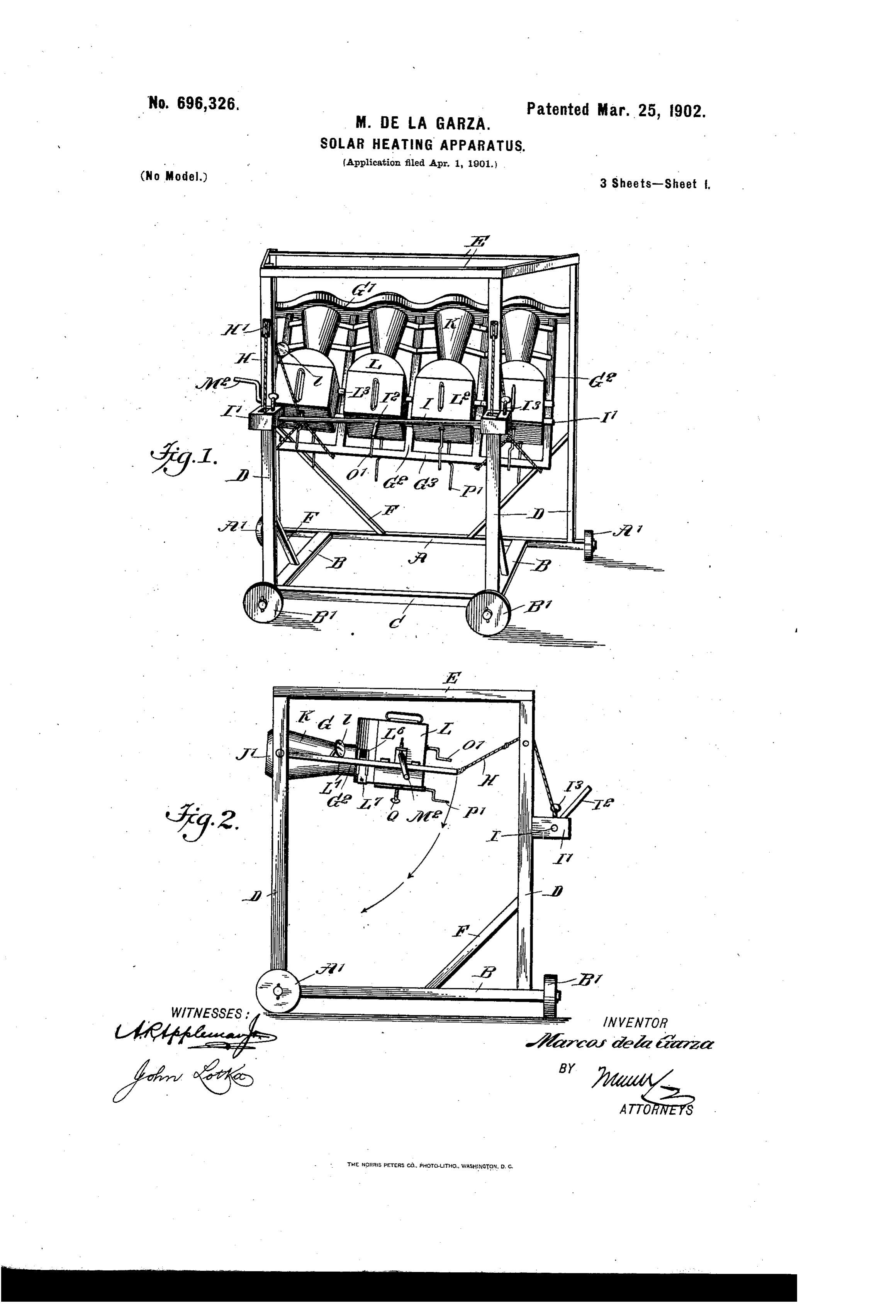
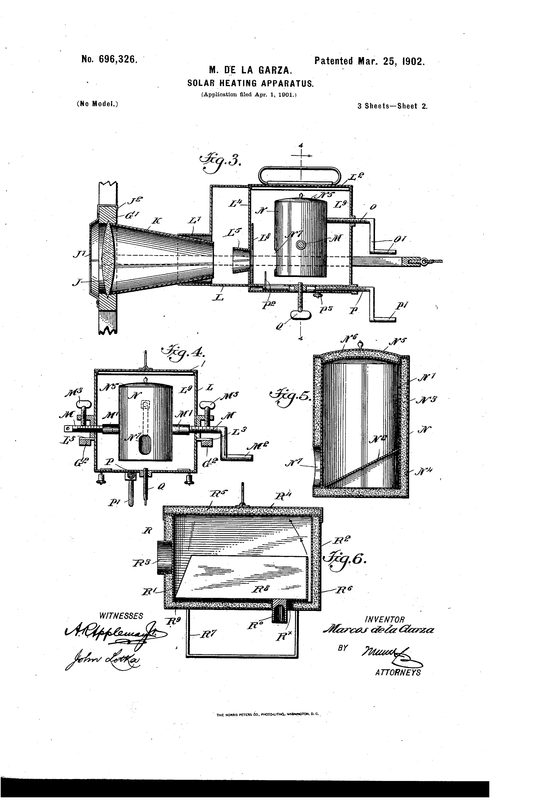
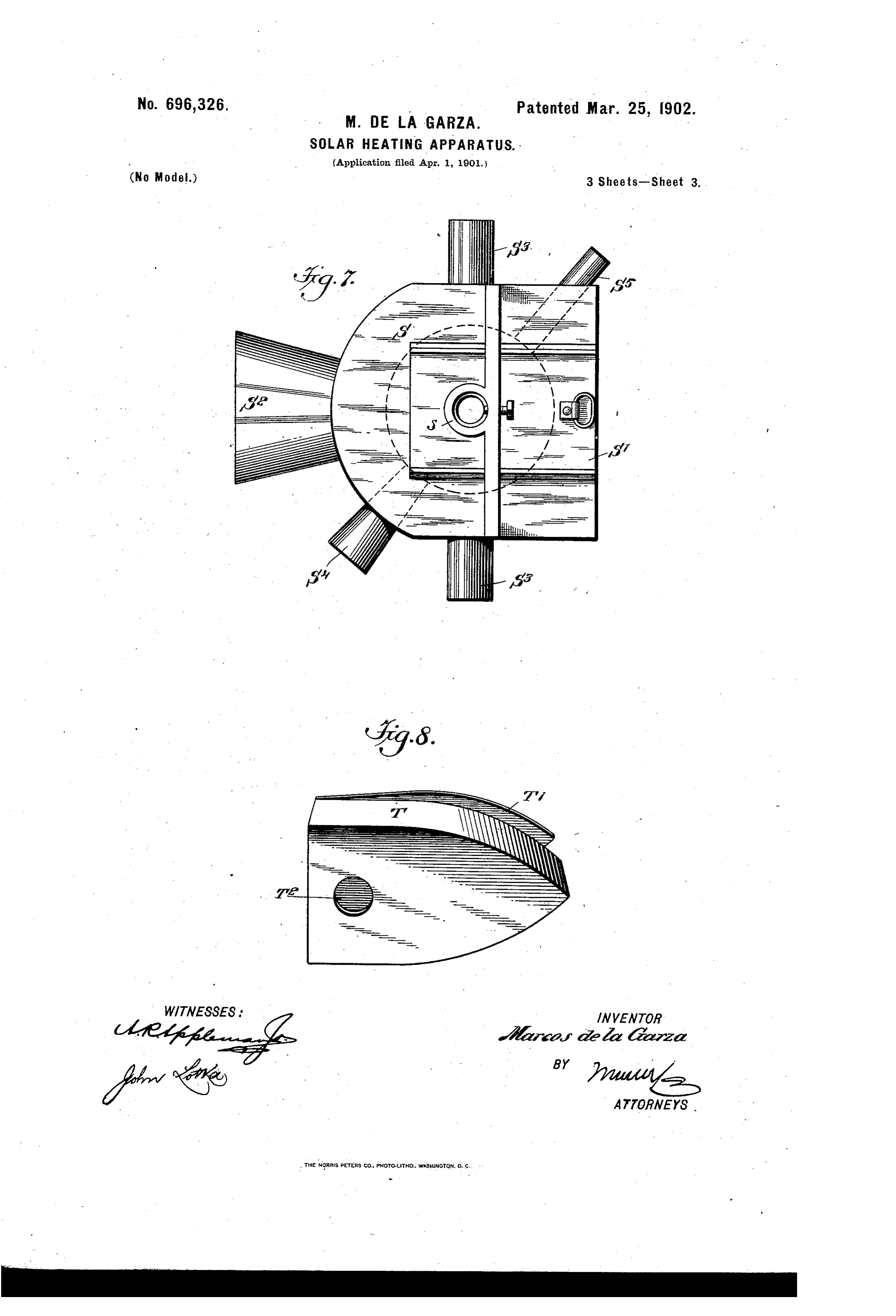
To all Luhon, it invay concern. the shaft, and I represents set-screws adapted Beit known that I, MARCOS DE LA GARZA, to engage the shaft to lock the same. a citizen of the Republic of Mexico, and a resi- In the head G' are set lenses J, biconvex, dent of Chihuahua, Mexico, have invented a as shown, or of any other suitable shape. In 55 5 new and Improved Solar Heating Apparatus, front of the lenses are arranged hinged hoods of which the following is a full, clear, and ex- | caps J', provided with hooks J° to hold the act description. - hoods shut. Rearwardly from said lenses My invention relates to devices enabling there project tapering tubes K, blackened on the rays of the sun to be utilized for heating the inside to prevent reflections. These 60 Io purposes, saving the cost of fuel, and obtain- tubes at their rear ends fit into sockets L' ing a high degree of heat with cleanliness and upon the casings L., each provided with a without injurious action on the articles which handled lid Land with lugsL, resting on the are being cooked, while the cost of the appara- bars G. Each casing is provided with a par tus does not exceed that of an ordinary stove. tition L", having an opening and a funnel L 65 I5 The invention will be fully described here- projecting forwardly therefrom in axial aline inafter and the features of novelty pointed ment with the socket L" and lens-tube K. On out in the appended claims. the side of the casing IL is an opening L", adapt Reference is to be had to the accompanying led to be closed by a slide L, Fig. 2, for allow drawings, forming a part of this specification, ing the attendant to ascertain if the sun's rays 7o 20 in which similar characters of reference indi- fall in the desired direction. Preferably a cate corresponding parts in all the figures. mirror l is provided to enable the attendant Figure 1 is a perspective view of the entire to view the inside of the apparatus from the apparatus. Fig. 2 is a side elevation there- rear. An apertured shield L. may be located . of. Fig. 3 is a detail longitudinal sectional in the rear of the funnel or cone L. In the 75 25 elevation of one of the cooking utensils and chamber L' at the rear of the partition Lex its appurtenances. Fig. 4 is a cross-section tends a transverse shaft formed of outer sec on line 4 4 of Fig. 3. Figs. 5 and 6 are sec- tions M, adapted to engage alining sockets tional elevations of two other forms of cook- M', projecting from the cooking vessel N. ing utensils. Fig. 7 is a plan of a receptacle One of the shaft-sections M has a crank M 8o. 3o for heating metals, and Fig. 8 is a perspec- for turning the shaft and the vessel; but such tive view of a casing for heating sad-irons. cranks are provided only on the first and last The apparatus comprises a framehaving a receptacles or casings L of the series, and the longitudinal bottom bar A, the ends of which adjacent shaft-sections M of the several cas form axles for wheels A", horizontal cross-lings are connected with each other, so that 85 35 bars B, with wheels B' journaled at one end all the vessels N may be adjusted together. of each of them, a short longitudinal bar C, Through the rear wall of the casing L. passes connecting the bars Badjacent to the wheels a shaft O, provided with a crank O' and B', uprights D, rising from the bottom bars, adapted to engage the vessel N above the top bars E, connecting the upper ends of the sockets M'. At the bottom is located a shaft go 4o uprights, and braces F, connected with the P, having a crank P and a projection P'ex uprights and with the bottom bars. tending into the chamber L. A set-screw P. To two of the uprights D is pivoted a swing- serves to lock the shaft P, and set-screws M ing frame G, having a head G' at its pivoted lock the shaft Mafter adjustment. Through end and parallel bars G° connecting said the bottom of the casing projects a screw Q, 95 45 head with the opposite end bar G8 of the adapted to engage the bottom of the vessel swinging frame. To the said end bar are se- N to hold the same firmly in position after cured cords or wires H, passing over pulleys adjustment.
H', journaled in two of the uprights D, said The cooking vessel N (shown in Figs. 3, 4, cords then passing to boxes I", surrounding a and 5) has an inner Wall N', with an inclined Io) 5o winding-shaft I, to which the ends of the bottom. N, and an outer wall N, spaced from cords are fastened. I is a crank for turning the inner wall to form a jacket, which is filled
Page 5
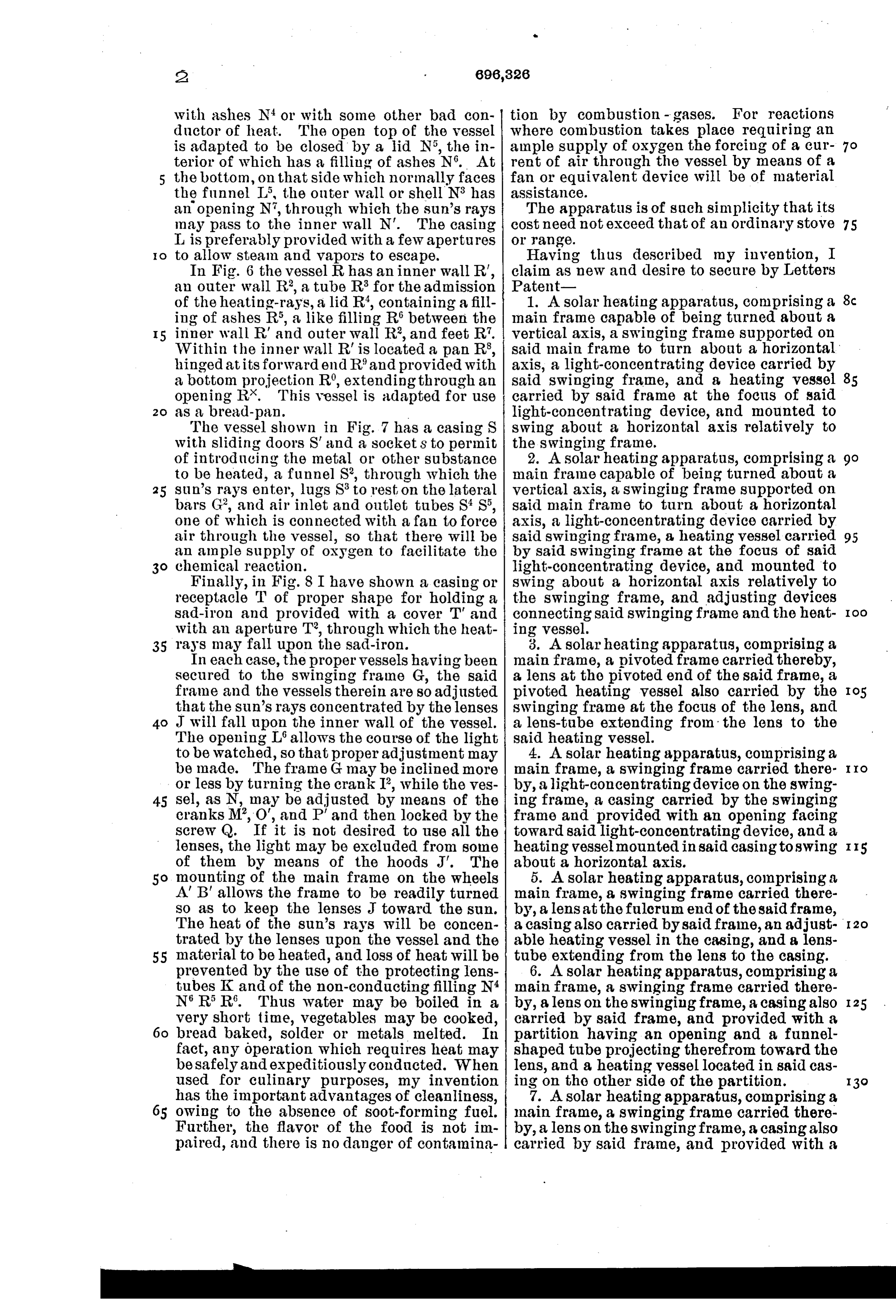
with ashes N' or with some other bad con tion by combustion - gases. For reactions ductor of heat. The open top of the vessel where combustion takes place requiring an is adapted to be closed by a lid N, the in ample supply of oxygen the forcing of a cur terior of which has a filling of ashes N. At rent of air through the vessel by means of a the bottom, on that side which normally faces fan or equivalent device will be of material the funnel L, the outer wall or shell N8 has assistance.
an opening N, through which the sun's rays The apparatus is of such simplicity that its may pass to the inner wall N'. The casing cost need not exceed that of an ordinary stove 75 L is preferably provided with a few apertures Or range.
to allow steam and vapors to escape. Having thus described my invention, I In Fig. 6 the vessel R has an inner wall R', claim as new and desire to secure by Letters an outer wall R, a tube R for the admission Patent of the heating-rays, a lid R, containing a fill 1. A solar heating apparatus, comprising a ing of ashes R., a like filling R between the main frame capable of being turned about a inner wall R' and outer wall R, and feet R. vertical axis, a swinging frame supported. On Within the inner wall R is located a pan R, said main frame to turn about a horizontal hinged at its forward end Rand provided with axis, a light-concentrating device carried by a bottom projection R', extending through an said swinging frame, and a heating vessel opening R*. This vessel is adapted for use carried by said frame at the focus of said as a bread-pan. light-concentrating device, and mounted to The vessel shown in Fig. 7 has a casing S swing about a horizontal axis relatively to with sliding doors S and a sockets to permit the swinging frame.
of introducing the metal or other substance 2. A solar heating apparatus, comprising a to be heated, a funnel S, through which the main frame capable of being turned about a 25 sun's rays enter, lugs S to rest on the lateral vertical axis, a swinging frame supported on bars G, and air inlet and outlet tubes SS, said main frame to turn about a horizontal one of which is connected with a fan to force axis, a light-concentrating device carried by air through the vessel, so that there will be said swinging frame, a heating vessel carried 95 an ample supply of oxygen to facilitate the by said swinging frame at the focus of said chemical reaction. light-concentrating device, and mounted to Finally, in Fig. 8 I have shown a casing or swing about a horizontal axis relatively to receptacle T of proper shape for holding a the swinging frame, and adjusting devices sad-iron and provided with a cover T and connecting said swinging frame and the heat do with an aperture T, through which the heat ing vessel.
35 rays may fall upon the sad-iron. 3. A solar heating apparatus, comprising a In each case, the proper vessels having been main frame, a pivoted frame carried thereby, secured to the swinging frame G, the said a lens at the pivoted end of the said frame, a frame and the vessels therein are so adjusted pivoted heating vessel also carried by the Io5 that the sun's rays concentrated by the lenses swinging frame at the focus of the lens, and J will fall upon the inner wall of the vessel. a lens-tube extending from the lens to the The opening Lallows the course of the light said heating vessel.
to be watched, so that proper adjustment may 4. A solar heating apparatus, comprising a be made. The frame G may be inclined more main frame, a swinging frame carried there o or less by turning the crank I, while the ves by, a light-concentrating device on the swing 45 Sel, as N, may be adjusted by means of the ing frame, a casing carried by the swinging cranks M', 'O', and P and then locked by the frame and provided with an opening facing Screw Q. If it is not desired to use all the toward said light-concentrating device, and a lenses, the light may be excluded from some heating vesselmounted in said casing to Swing IIS of them by means of the hoods J. The about a horizontal axis.
So mounting of the main frame on the wheels 5. A solar heating apparatus, comprising a A'B' allows the frame to be readily turned main frame, a swinging frame carried there SO as to keep the lenses J toward the sun. by, a lens at the fulcrum end of the said frame, The heat of the sun's rays will be concen a casing also carried by said frame, an adjust trated by the lenses upon the vessel and the able heating vessel in the casing, and a lens 55 material to be heated, and loss of heat will be tube extending from the lens to the casing. prevented by the use of the protecting lens 6. A solar heating apparatus, comprising a tubes K and of the non-conducting filling N4 main frame, a swinging frame carried there N. R. R. Thus water may be boiled in a by, a lens on the swinging frame, a casing also I 25 very short time, vegetables may be cooked, carried by said frame, and provided with a bread baked, solder or metals melted. In partition having an opening and a funnel fact, any operation which requires heat may shaped tube projecting therefrom toward the be safely and expeditiously conducted. When lens, and a heating vessel located in said cas used for culinary purposes, my invention ing on the other side of the partition. has the important advantages of cleanliness, 7. A Solar heating apparatus, comprising a owing to the absence of soot-forming fuel. main frame, a swinging frame carried there Further, the flavor of the food is not im by, a lens on the swinging frame, a casing also paired, and there is no danger of contamina carried by said frame, and provided with a
Page 6
partition having an opening and a funnel tube, and with a partition dividing the cas shaped tube projecting therefrom toward the ing into two compartments, said partition hav lens, a heating vessel located in said casing ing an opening in alinement with the open on the other side of the partition, and a lens ing of the casing and a funnel around said 5 tube extending from the lens to the casing. opening, and a heating vessel adjustably 8. In a solar heating apparatus, the combi mounted in one compartment of the casing nation with a casing, and a sectional shaft and provided with an opening in its lower. mounted therein, one section being provided portion opposite the opening in the partition. with a crank, of a heating vessel within the ll. In a solar heating apparatus, the com 35 Io casing and provided with alining sockets to bination with a support, and a plurality of receive the shaft-sections, and means for lock casings carried by the support and arranged ing the vessel in position. side by side, of a heating vessel in each cas 9. In a solar heating apparatus, the combi ing and provided with alining sockets, and a nation of a casing provided with an opening Sectional shaft carried by each casing and en I5 and with a partition dividing it into two com tering the sockets of the heating vessel, the partments said partition having an opening adjacent shaft-sections of the several casings from which a funnel projects, and a heating being connected, and one section of an end vessel adjustably supported in one compart casing being provided with a crank-handle, ment of the casing and provided with an open as set-forth. 45 2O ing in its lower portion. In testimony whereof I have signed my 10. A solar heating apparatus, comprising name to this specification in the presence of * a main frame, a swinging frame mounted in two subscribing witnesses.
the main frame, a lens carried by the swing MARCOS DE LA GARZA, ing frame, a tube extending from the lens, a Witnesses:
25 casing also carried by the swinging frame and BENIGNO LOYA, provided with an opening receiving the lens LONGINOS BALDERMANN.
Provenance
- Collection
- Cited prior art
- Original PDF
- patentimages.storage.googleapis.com →
- Filed
- 1901-04-01
- Pages
- 6
- Method
- pdftotext (the PDF's own text layer) + pdftoppm 300dpi page scans
- Source
- Google Patents bibliographic record
- Granted
- 1902-03-25
- Inventors
- Marcos De La Garza
- Transcribed from
- patentimages.storage.googleapis.com →