patent · US4092979
Combined solar energy conversion and structural and mechanical beam and structures built therefrom
6 June 1978
Page 1 — bibliographic record
United States Patent 19 (11) 4,092,979 Kotlarz 45 June 6, 1978 54 COMBINED SOLARENERGY CONVERSION Attorney, Agent, or Firm-Gildo E. Fato
AND STRUCTURAL AND MECHANICAL
BEAMAND STRUCTURES BUILT 57 ABSTRACT
THEREFROM Disclosed is a combined solar energy conversion and 76 Inventor: Joseph C. Kotlarz, 109 W. structural and mechanical beam. The beam comprises a pre-engineered structural and mechanical component
Woodlawn Dr., Mundelein, Ill. which includes a solar energy collector or distributor 60060 and can be used to erect a complete structure or as 21 Appl. No.: 738,845 retrofite hardware for existing buildings or structures. In one embodiment, the solar collector portion of the 22 Filed: Nov. 4, 1976 beam consists of a highly polished parabolic concentra 51) Int. C.’................................................. F24, 3/02 tor within a channel-shaped portion of the beam, an 52 U.S. C. .................................... 126/271; 237/1 A absorber tube disposed within the concentrator for re 58) Field of Search ................ 126/271, 270; 237/1 A taining the fluid to be heated, and an optical or fresnel lens positioned over the open side of the beam to further 56 References Cited concentrate the sun and sky radiation. Other portions of
manifold system to transport the fluid heated by the 1,683,266 9/1928 Shipman .............................. 26/271 solar collector portion, or a distributor or diffuser can 3,990,914 11/1976 Weinstein et al. ... ... 126/270 be disposed therein to facilitate the flow of warm or 4,011,857 3/1977 Rice .................. ... 126/271 cool air into the desired area. 4,038,971 8/1977 Bezborodko ......................... 126/271
Primary Examiner-Carroll B. Dority, Jr. 10 Claims, 6 Drawing Figures
Page 2
Drawing sheet — no readable text.
Page 3
Drawing sheet — no readable text.
Page 4
Drawing sheet — no readable text.
Page 5
transfer pipe at the focus of the system. The pipe is
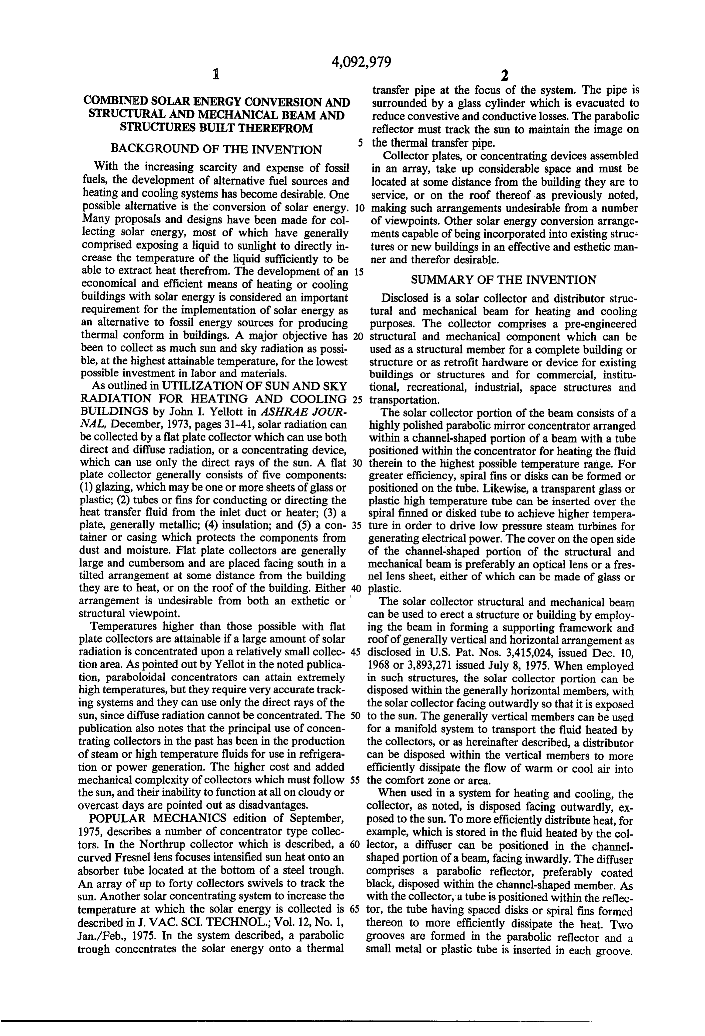
COMBINED SOLAR ENERGY CONVERSION AND surrounded by a glass cylinder which is evacuated to STRUCTURAL AND MECHANICAL BEAM AND reduce convestive and conductive losses. The parabolic STRUCTURES BUILT THEREFROM reflector must track the sun to maintain the image on BACKGROUND OF THE INVENTION the thermal transfer pipe.
Collector plates, or concentrating devices assembled
With the increasing scarcity and expense of fossil in an array, take up considerable space and must be fuels, the development of alternative fuel sources and located at some distance from the building they are to heating and cooling systems has become desirable. One service, or on the roof thereof as previously noted, possible alternative is the conversion of solar energy. 10 making such arrangements undesirable from a number Many proposals and designs have been made for col of viewpoints. Other solar energy conversion arrange lecting solar energy, most of which have generally ments capable of being incorporated into existing struc comprised exposing a liquid to sunlight to directly in tures or new buildings in an effective and esthetic man crease the temperature of the liquid sufficiently to be ner and therefor desirable.
able to extract heat therefrom. The development of an 15 SUMMARY OF THE INVENTION economical and efficient means of heating or cooling buildings with solar energy is considered an important Disclosed is a solar collector and distributor struc requirement for the implementation of solar energy as tural and mechanical beam for heating and cooling an alternative to fossil energy sources for producing purposes. The collector comprises a pre-engineered thermal conform in buildings. A major objective has 20 structural and mechanical component which can be been to collect as much sun and sky radiation as possi used as a structural member for a complete building or ble, at the highest attainable temperature, for the loweststructure or as retrofit hardware or device for existing possible investment in labor and materials. buildings or structures and for commercial, institu As outlined in UTILIZATION OF SUN AND SKY tional, recreational, industrial, space structures and RADIATION FOR HEATING AND COOLING 25 transportation.
BUILDINGS by John I. Yellott in ASHRAE JOUR The solar collector portion of the beam consists of a NAL, December, 1973, pages 31-41, solar radiation can highly polished parabolic mirror concentrator arranged be collected by a flat plate collector which can use both within a channel-shaped portion of a beam with a tube direct and diffuse radiation, or a concentrating device, positioned within the concentrator for heating the fluid which can use only the direct rays of the sun. A flat 30 therein to the highest possible temperature range. For plate collector generally consists of five components: greater efficiency, spiral fins or disks can be formed or (1) glazing, which may be one or more sheets of glass or positioned on the tube. Likewise, a transparent glass or plastic; (2) tubes or fins for conducting or directing the plastic high temperature tube can be inserted over the heat transfer fluid from the inlet duct or heater; (3) a spiral finned or disked tube to achieve higher tempera plate, generally metallic; (4) insulation; and (5) a con 35 ture in order to drive low pressure steam turbines for tainer or casing which protects the components from generating electrical power. The cover on the open side dust and moisture. Flat plate collectors are generally of the channel-shaped portion of the structural and large and cumbersom and are placed facing south in a mechanical beam is preferably an optical lens or a fres tilted arrangement at some distance from the building nel lens sheet, either of which can be made of glass or they are to heat, or on the roof of the building. Either plastic.
arrangement is undesirable from both an exthetic or The solar collector structural and mechanical beam structural viewpoint. can be used to erect a structure or building by employ Temperatures higher than those possible with flat ing the beam in forming a supporting framework and plate collectors are attainable if a large amount of solar roof of generally vertical and horizontal arrangement as radiation is concentrated upon a relatively small collec 45 disclosed in U.S. Pat. Nos. 3,415,024, issued Dec. 10, tion area. As pointed out by Yellot in the noted publica 1968 or 3,893,271 issued July 8, 1975. When employed tion, paraboloidal concentrators can attain extremely in such structures, the solar collector portion can be high temperatures, but they require very accurate track disposed within the generally horizontal members, with ing systems and they can use only the direct rays of the the solar collector facing outwardly so that it is exposed sun, since diffuse radiation cannot be concentrated. The 50 to the sun. The generally vertical members can be used publication also notes that the principal use of concen for a manifold system to transport the fluid heated by trating collectors in the past has been in the production the collectors, or as hereinafter described, a distributor of steam or high temperature fluids for use in refrigera can be disposed within the vertical members to more tion or power generation. The higher cost and added efficiently dissipate the flow of warm or cool air into mechanical complexity of collectors which must follow 55 the comfort zone or area.
the sun, and their inability to function at all on cloudy or When used in a system for heating and cooling, the overcast days are pointed out as disadvantages. collector, as noted, is disposed facing outwardly, ex POPULAR MECHANICS edition of September, posed to the sun. To more efficiently distribute heat, for 1975, describes a number of concentrator type collec example, which is stored in the fluid heated by the col tors. In the Northrup collector which is described, a 60 lector, a diffuser can be positioned in the channel curved Fresnel lens focuses intensified sun heat onto an shaped portion of a beam, facing inwardly. The diffuser absorber tube located at the bottom of a steel trough. comprises a parabolic reflector, preferably coated An array of up to forty collectors swivels to track the black, disposed within the channel-shaped member. As sun. Another solar concentrating system to increase the with the collector, a tube is positioned within the reflec temperature at which the solar energy is collected is 65 tor, the tube having spaced disks or spiral fins formed described in J. VAC, SCI. TECHNOL.; Vol. 12, No. 1, thereon to more efficiently dissipate the heat. Two Jan/Feb., 1975. In the system described, a parabolic grooves are formed in the parabolic reflector and a trough concentrates the solar energy onto a thermal small metal or plastic tube is inserted in each groove.
Page 6
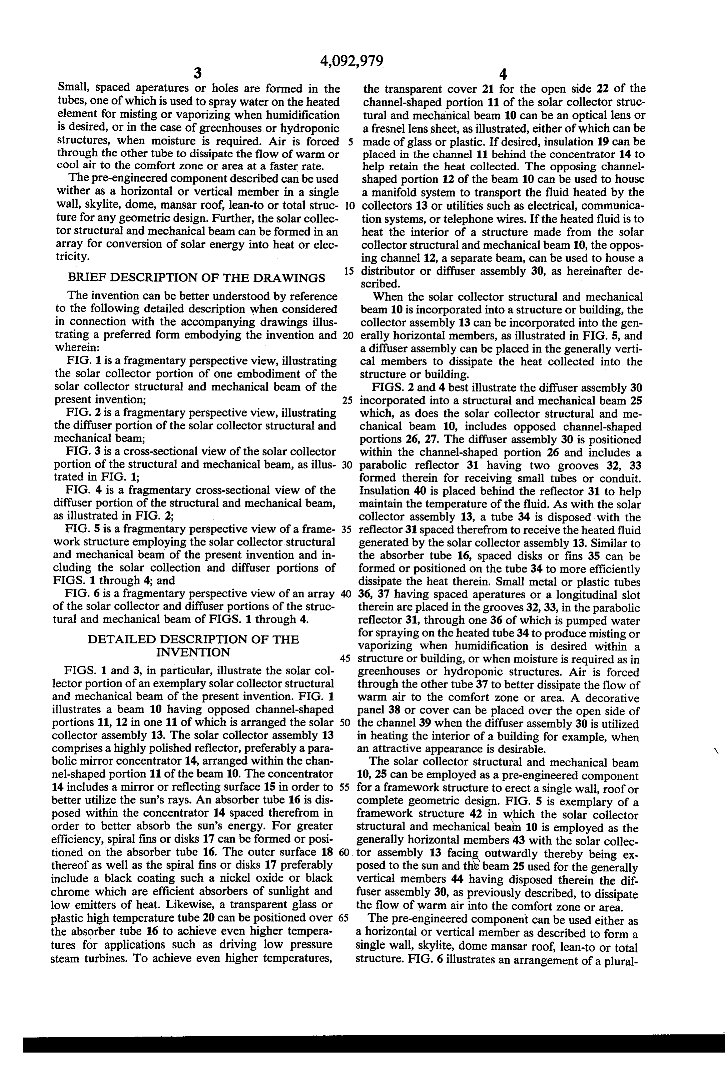
Small, spaced aperatures or holes are formed in the the transparent cover 21 for the open side 22 of the tubes, one of which is used to spray water on the heated channel-shaped portion 11 of the solar collector struc element for misting or vaporizing when humidification tural and mechanical beam 10 can be an optical lens or is desired, or in the case of greenhouses or hydroponic a fresnel lens sheet, as illustrated, either of which can be structures, when moisture is required. Air is forced 5 made of glass or plastic. If desired, insulation 19 can be through the other tube to dissipate the flow of warm or placed in the channel 11 behind the concentrator 14 to cool air to the comfort zone or area at a faster rate. help retain the heat collected. The opposing channel The pre-engineered component described can be used shaped portion 12 of the beam 10 can be used to house wither as a horizontal or vertical member in a single a manifold system to transport the fluid heated by the wall, skylite, dome, mansar roof, lean-to or total struc 10 collectors 13 or utilities such as electrical, communica ture for any geometric design. Further, the solar collec tion systems, or telephone wires. If the heated fluid is to tor structural and mechanical beam can be formed in an heat the interior of a structure made from the solar array for conversion of solar energy into heat or elec collector structural and mechanical beam 10, the oppos tricity. ing channel 12, a separate beam, can be used to house a 15 distributor or diffuser assembly 30, as hereinafter de
BRIEF DESCRIPTION OF THE DRAWINGS scribed.
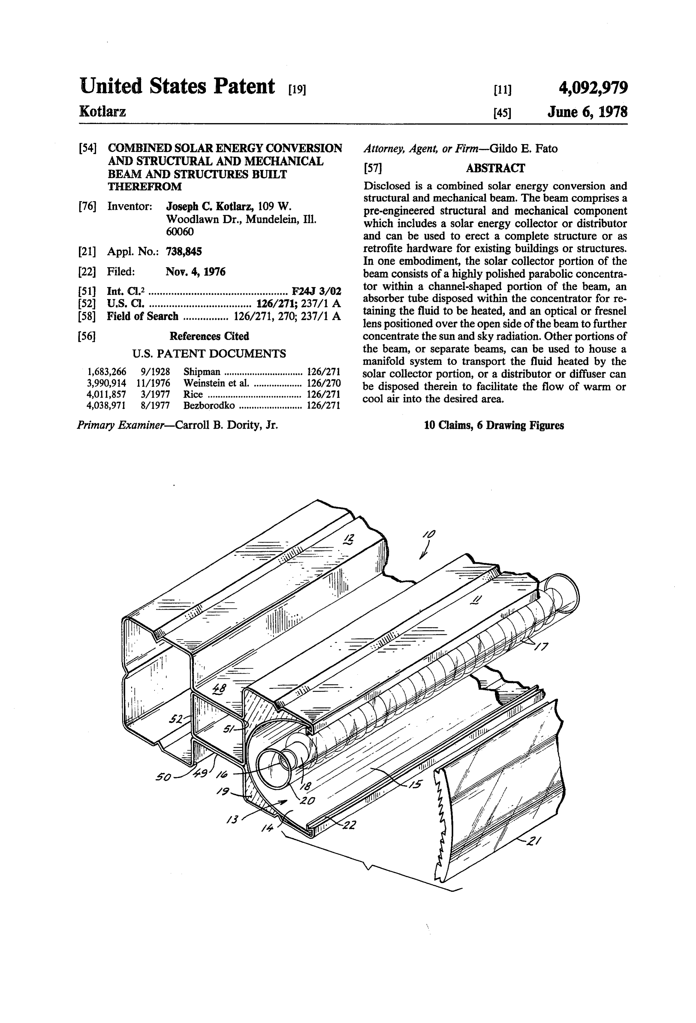
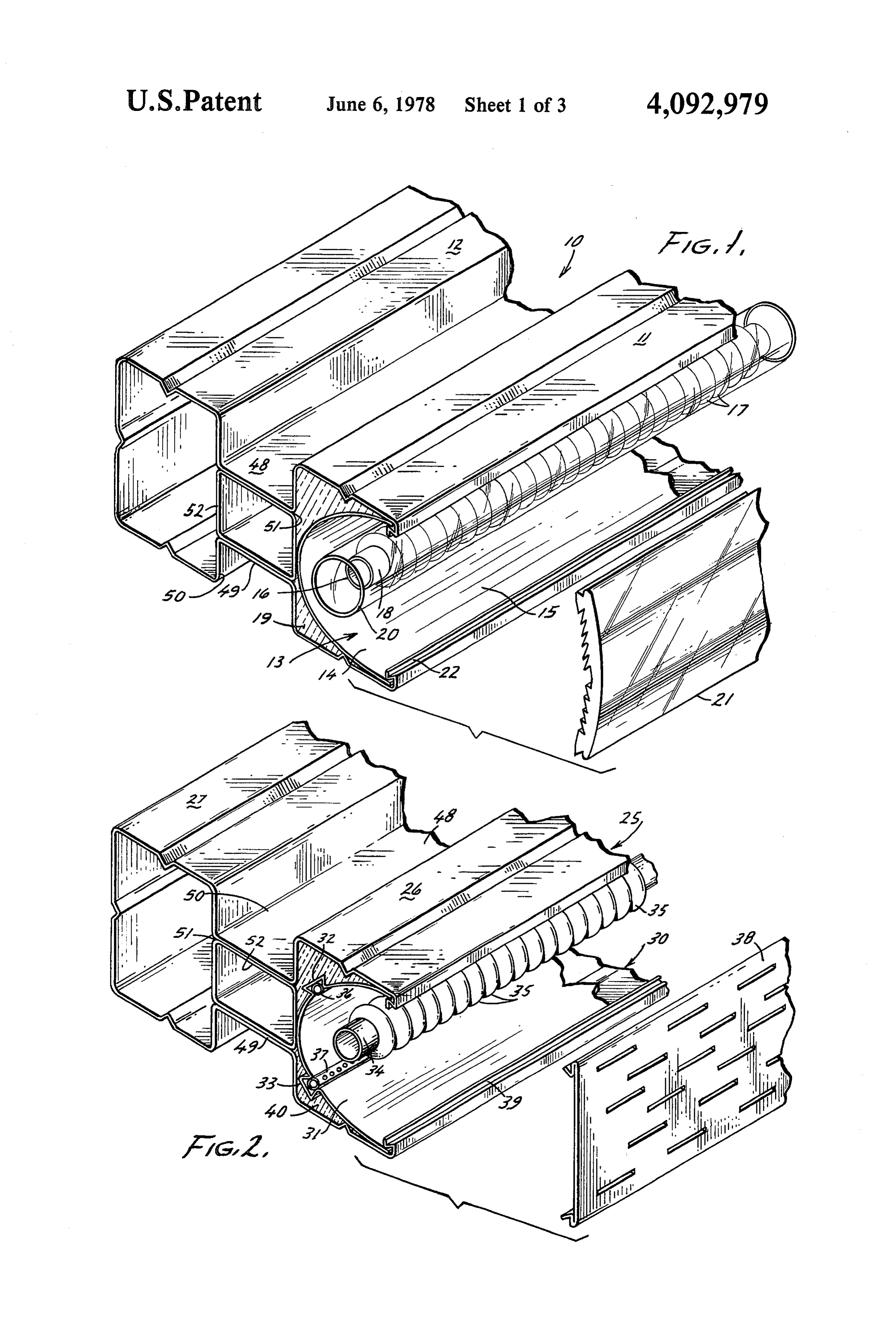
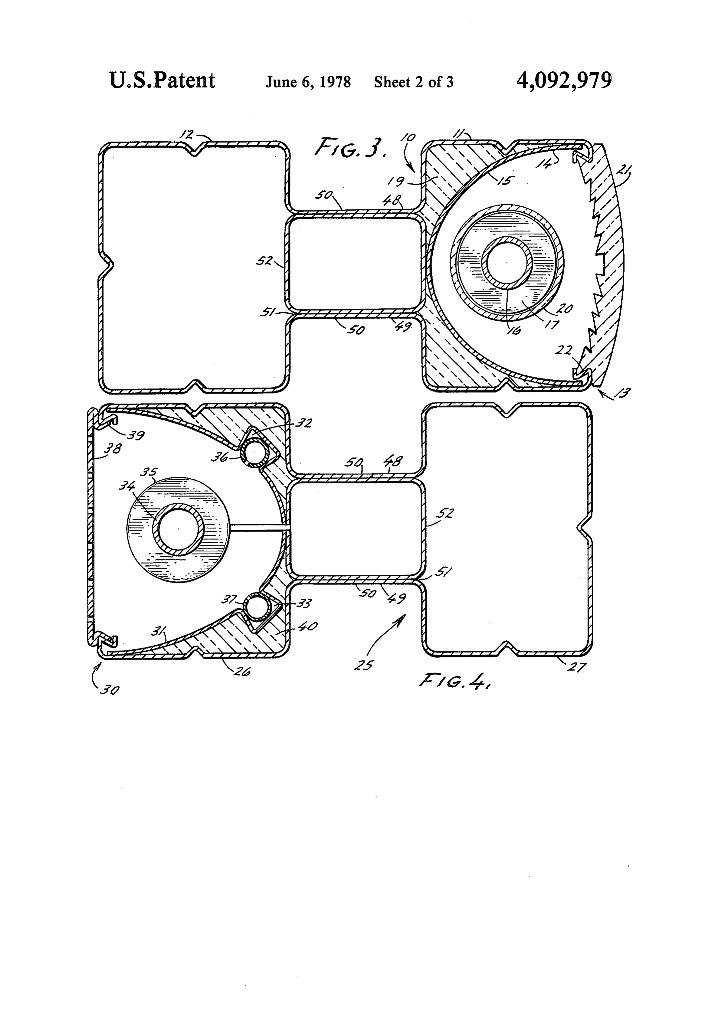
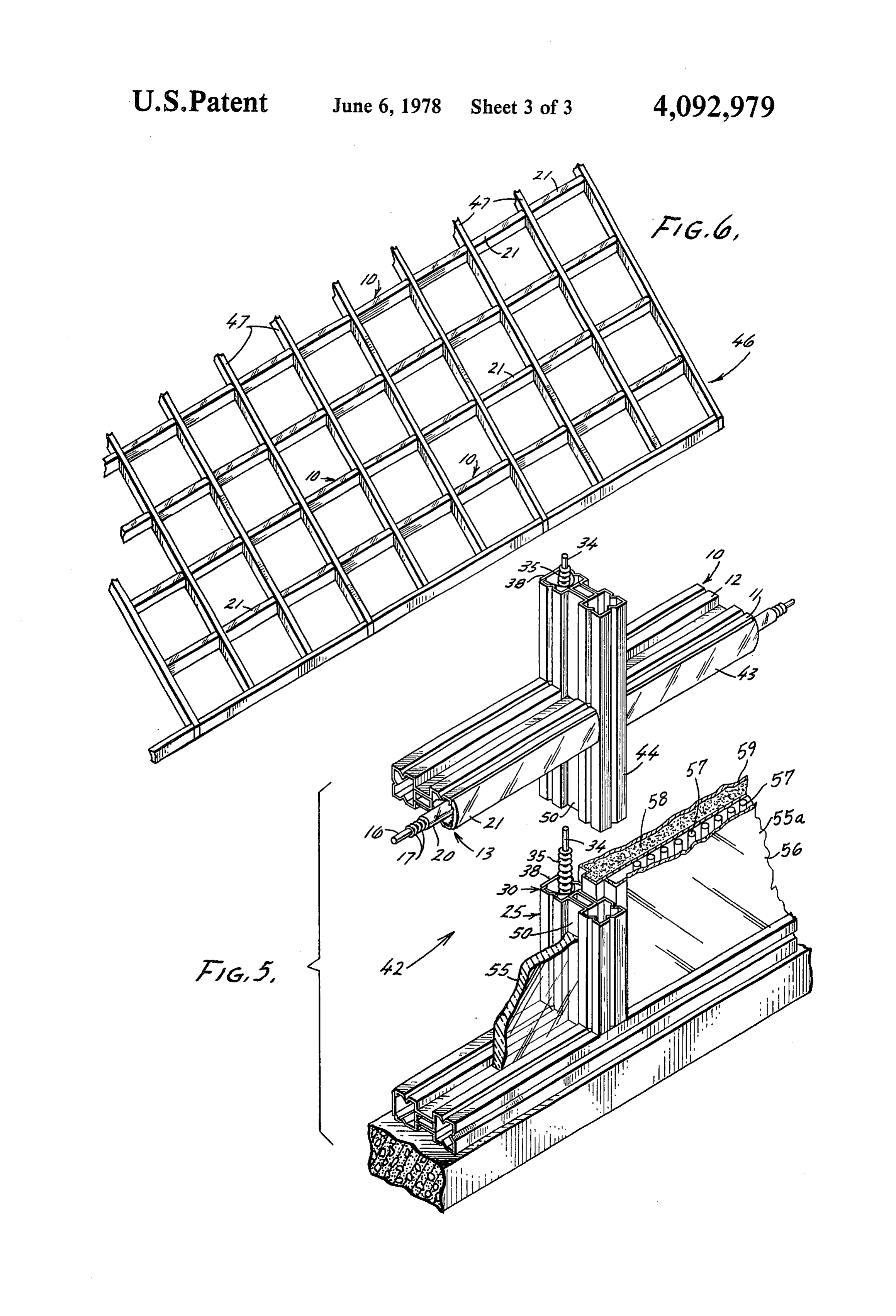
The invention can be better understood by reference When the solar collector structural and mechanical to the following detailed description when considered beam 10 is incorporated into a structure or building, the in connection with the accompanying drawings illus collector assembly 13 can be incorporated into the gen trating a preferred form embodying the invention and 20 erally horizontal members, as illustrated in FIG. 5, and wherein: a diffuser assembly can be placed in the generally verti FIG. 1 is a fragmentary perspective view, illustrating cal members to dissipate the heat collected into the the solar collector portion of one embodiment of the structure or building.
solar collector structural and mechanical beam of the FIGS. 2 and 4 best illustrate the diffuser assembly 30 present invention; 25 incorporated into a structural and mechanical beam 25 FIG. 2 is a fragmentary perspective view, illustrating which, as does the solar collector structural and me the diffuser portion of the solar collector structural and chanical beam 10, includes opposed channel-shaped mechanical beam; portions 26, 27. The diffuser assembly 30 is positioned FIG. 3 is a cross-sectional view of the solar collector within the channel-shaped portion 26 and includes a portion of the structural and mechanical beam, as illus 30 parabolic reflector 31 having two grooves 32, 33 trated in FIG. 1; formed therein for receiving small tubes or conduit. FIG. 4 is a fragmentary cross-sectional view of the Insulation 40 is placed behind the reflector 31 to help diffuser portion of the structural and mechanical beam, maintain the temperature of the fluid. As with the solar as illustrated in FIG. 2; collector assembly 13, a tube 34 is disposed with the FIG. 5 is a fragmentary perspective view of a frame 35 reflector 31 spaced therefrom to receive the heated fluid work structure employing the solar collector structural generated by the solar collector assembly 13. Similar to and mechanical beam of the present invention and in the absorber tube 16, spaced disks or fins 35 can be cluding the solar collection and diffuser portions of formed or positioned on the tube 34 to more efficiently FIGS. 1 through 4; and dissipate the heat therein. Small metal or plastic tubes FIG. 6 is a fragmentary perspective view of an array 40 36, 37 having spaced aperatures or a longitudinal slot of the solar collector and diffuser portions of the struc therein are placed in the grooves 32,33, in the parabolic tural and mechanical beam of FIGS. 1 through 4. reflector 31, through one 36 of which is pumped water DETAILED DESCRIPTION OF THE for spraying on the heated tube 34 to produce misting or INVENTION vaporizing when humidification is desired within a 45 structure or building, or when moisture is required as in
FIGS. 1 and 3, in particular, illustrate the solar col greenhouses or hydroponic structures. Air is forced lector portion of an exemplary solar collector structural through the other tube 37 to better dissipate the flow of and mechanical beam of the present invention. FIG. 1 warm air to the comfort zone or area. A decorative illustrates a beam 10 having opposed channel-shaped panel 38 or cover can be placed over the open side of portions 11, 12 in one 11 of which is arranged the solar 50 the channel 39 when the diffuser assembly 30 is utilized collector assembly 13. The solar collector assembly 13 in heating the interior of a building for example, when comprises a highly polished reflector, preferably a para an attractive appearance is desirable. bolic mirror concentrator 14, arranged within the chan The solar collector structural and mechanical beam nel-shaped portion 11 of the beam 10. The concentrator 10, 25 can be employed as a pre-engineered component 14 includes a mirror or reflecting surface 15 in order to 55 for a framework structure to erect a single wall, roof or better utilize the sun's rays. An absorber tube 16 is dis complete geometric design. FIG. 5 is exemplary of a posed within the concentrator 14 spaced therefrom in framework structure 42 in which the solar collector order to better absorb the sun's energy. For greater structural and mechanical beam 10 is employed as the efficiency, spiral fins or disks 17 can be formed or posi generally horizontal members 43 with the solar collec tioned on the absorber tube 16. The outer surface 18 60 tor assembly 13 facing outwardly thereby being ex thereof as well as the spiral fins or disks 17 preferably posed to the sun and the beam 25 used for the generally include a black coating such a nickel oxide or black vertical members 44 having disposed therein the dif chrome which are efficient absorbers of sunlight and fuser assembly 30, as previously described, to dissipate low emitters of heat. Likewise, a transparent glass or the flow of warm air into the comfort zone or area. plastic high temperature tube 20 can be positioned over 65 The pre-engineered component can be used either as the absorber tube 16 to achieve even higher tempera a horizontal or vertical member as described to form a tures for applications such as driving low pressure single wall, skylite, dome mansar roof, lean-to or total steam turbines. To achieve even higher temperatures, structure. FIG. 6 illustrates an arrangement of a plural
Page 7
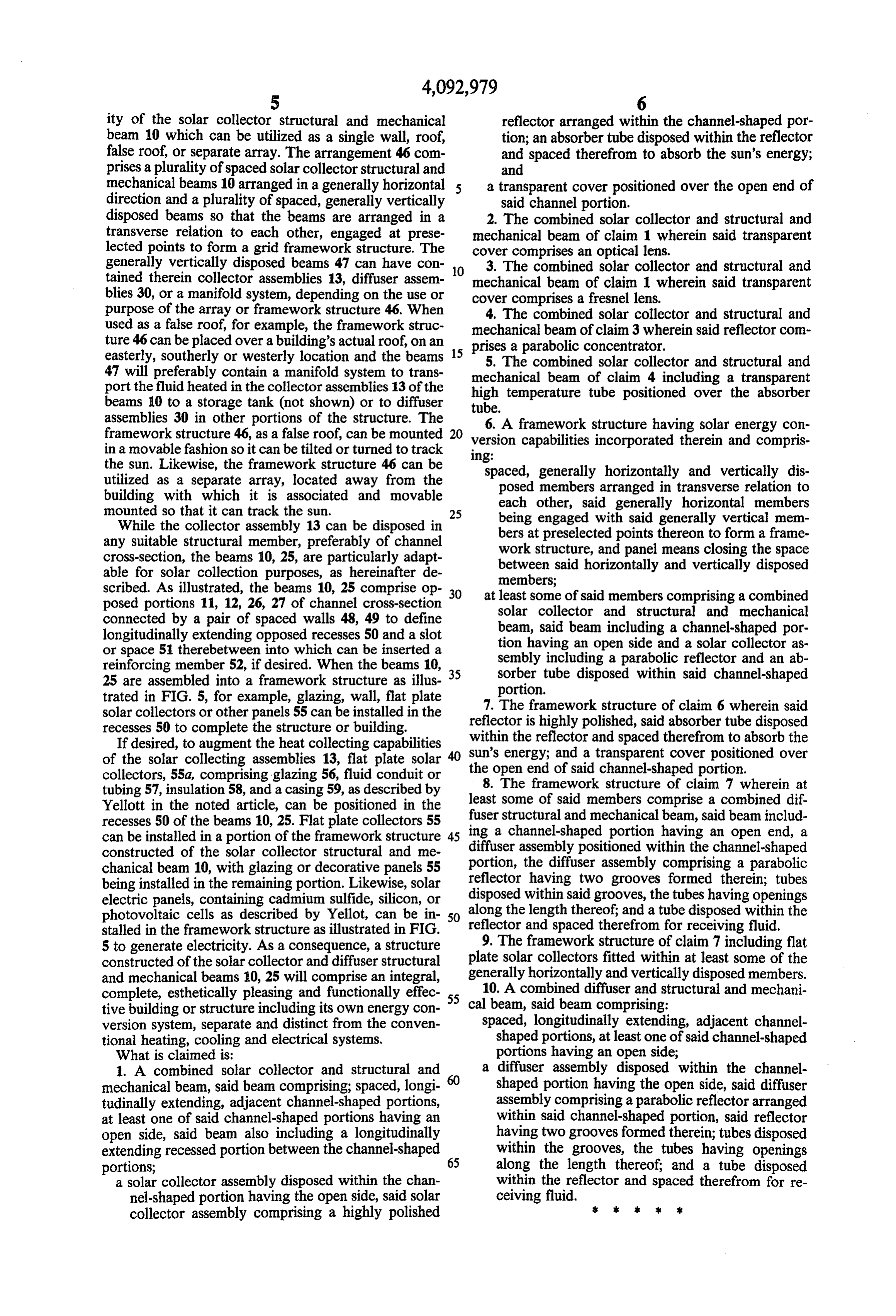
ity of the solar collector structural and mechanical reflector arranged within the channel-shaped por beam 10 which can be utilized as a single wall, roof, tion; an absorber tube disposed within the reflector false roof, or separate array. The arrangement 46 com and spaced therefrom to absorb the sun's energy; prises a plurality of spaced solar collector structural and and mechanical beams 10 arranged in a generally horizontal 5 a transparent cover positioned over the open end of direction and a plurality of spaced, generally vertically said channel portion.
disposed beams so that the beams are arranged in a 2. The combined solar collector and structural and transverse relation to each other, engaged at prese mechanical beam of claim 1 wherein said transparent lected points to form a grid framework structure. The cover comprises an optical lens.
generally vertically disposed beams 47 can have con 10 3. The combined solar collector and structural and tained therein collector assemblies 13, diffuser assem mechanical beam of claim 1 wherein said transparent blies 30, or a manifold system, depending on the use or cover comprises a fresnel lens. purpose of the array or framework structure 46. When 4. The combined solar collector and structural and used as a false roof, for example, the framework struc mechanical beam of claim 3 wherein said reflector com ture 46 can be placed over a building's actual roof, on an 15 prises a parabolic concentrator. easterly, southerly or westerly location and the beams 5. The combined solar collector and structural and 47 will preferably contain a manifold system to trans mechanical beam of claim 4 including a transparent port the fluid heated in the collector assemblies 13 of the high temperature tube positioned over the absorber beams 10 to a storage tank (not shown) or to diffuser tube.
assemblies 30 in other portions of the structure. The 6. A framework structure having solar energy con framework structure 46, as a false roof, can be mounted 20 version capabilities incorporated therein and compris in a movable fashion so it can be tilted or turned to track 1ng:
the sun. Likewise, the framework structure 46 can be spaced, generally horizontally and vertically dis utilized as a separate array, located away from the posed members arranged in transverse relation to building with which it is associated and movable each other, said generally horizontal members mounted so that it can track the sun. 25 being engaged with said generally vertical mem While the collector assembly 13 can be disposed in bers at preselected points thereon to form a frame any suitable structural member, preferably of channel work structure, and panel means closing the space cross-section, the beams 10, 25, are particularly adapt between said horizontally and vertically disposed able for solar collection purposes, as hereinafter de members;
scribed. As illustrated, the beams 10, 25 comprise op 30 at least some of said members comprising a combined posed portions 11, 12, 26, 27 of channel cross-section solar collector and structural and mechanical connected by a pair of spaced walls 48, 49 to define beam, said beam including a channel-shaped por longitudinally extending opposed recesses 50 and a slot tion having an open side and a solar collector as or space 51 therebetween into which can be inserted a sembly including a parabolic reflector and an ab reinforcing member 52, if desired. When the beams 10, sorber tube disposed within said channel-shaped 25 are assembled into a framework structure as illus 35 portion.
trated in FIG. 5, for example, glazing, wall, flat plate 7. The framework structure of claim 6 wherein said solar collectors or other panels 55 can be installed in the reflector is highly polished, said absorber tube disposed recesses 50 to complete the structure or building. within the reflector and spaced therefrom to absorb the If desired, to augment the heat collecting capabilities Sun's energy; and a transparent cover positioned over of the solar collecting assemblies 13, flat plate solar the open end of said channel-shaped portion. collectors, 55a, comprising glazing 56, fluid conduit or 8. The framework structure of claim 7 wherein at tubing 57, insulation 58, and a casing 59, as described by least
Yellott in the noted article, can be positioned in the fuser some of said members comprise a combined dif recesses 50 of the beams 10, 25. Flat plate collectors 55 ing astructural and mechanical beam, said beam includ channel-shaped portion having an open end, a can be installed in a portion of the framework structure diffuser assembly positioned
within the channel-shaped constructed of the solar collector structural and me chanical beam 10, with glazing or decorative panels 55 portion, the diffuser assembly comprising a parabolic reflector having two grooves formed therein; tubes being installed in the remaining portion. Likewise, solar disposed within said grooves, the tubes having openings electric panels, containing cadmium sulfide, silicon, or along the length thereof; and a tube disposed within the photovoltaic cells as described by Yellot, can be in 50 reflector and spaced therefrom for receiving fluid. stalled in the framework structure as illustrated in FIG.
5 to generate electricity. As a consequence, a structure 9. The framework structure of claim 7 including flat constructed of the solar collector and diffuser structural plate solar collectors fitted within at least some of the and mechanical beams 10, 25 will comprise an integral, generally horizontally and vertically disposed members. complete, esthetically pleasing and functionally effec 55 10. A combined diffuser and structural and mechani tive building or structure including its own energy con calspaced, beam, said beam comprising:
longitudinally extending, adjacent channel version system, separate and distinct from the conven tional heating, cooling and electrical systems, shaped portions, at least one of said channel-shaped What is claimed is: portions having an open side; 1. A combined solar collector and structural and a diffuser assembly disposed within the channel mechanical beam, said beam comprising; spaced, longi shaped portion having the open side, said diffuser tudinally extending, adjacent channel-shaped portions, assembly comprising a parabolic reflector arranged at least one of said channel-shaped portions having an within said channel-shaped portion, said reflector open side, said beam also including a longitudinally having two grooves formed therein; tubes disposed extending recessed portion between the channel-shaped 65 within the grooves, the tubes having openings portions; along the length thereof; and a tube disposed a solar collector assembly disposed within the chan within the reflector and spaced therefrom for re nel-shaped portion having the open side, said solar ceiving fluid.
collector assembly comprising a highly polished . . . . .
Provenance
- Collection
- Cited prior art
- Original PDF
- patentimages.storage.googleapis.com →
- Filed
- 1976-11-04
- Pages
- 7
- Method
- pdftotext (the PDF's own text layer) + pdftoppm 300dpi page scans
- Source
- Google Patents bibliographic record
- Granted
- 1978-06-06
- Inventors
- Joseph C. Kotlarz
- Transcribed from
- patentimages.storage.googleapis.com →