patent · US1479923
Solar furnace
8 January 1924
Page 1
Drawing sheet — no readable text.
Page 2
Drawing sheet — no readable text.
Page 3
Drawing sheet — no readable text.
Page 4
Drawing sheet — no readable text.
Page 5
Patented Jan. 8, 1924. 1479,923
UNITED STATES PATENT OFFICE.
MARCEL E MOREAU, OF SAN FRANCISCO, CALIFORNLA
SOLAR, FURNACE,
Application fled April 10, 1922. Serial No. 551,294.
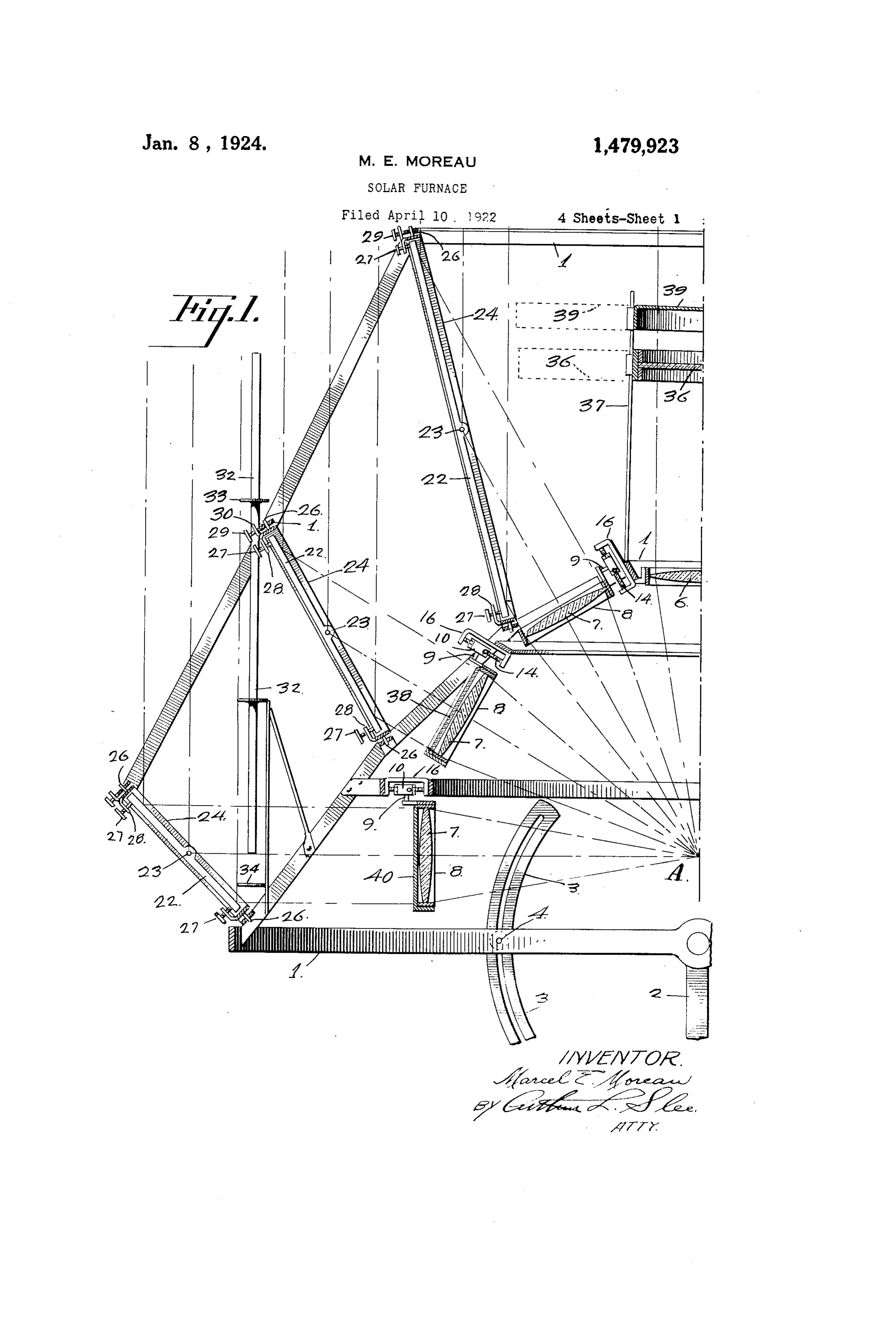
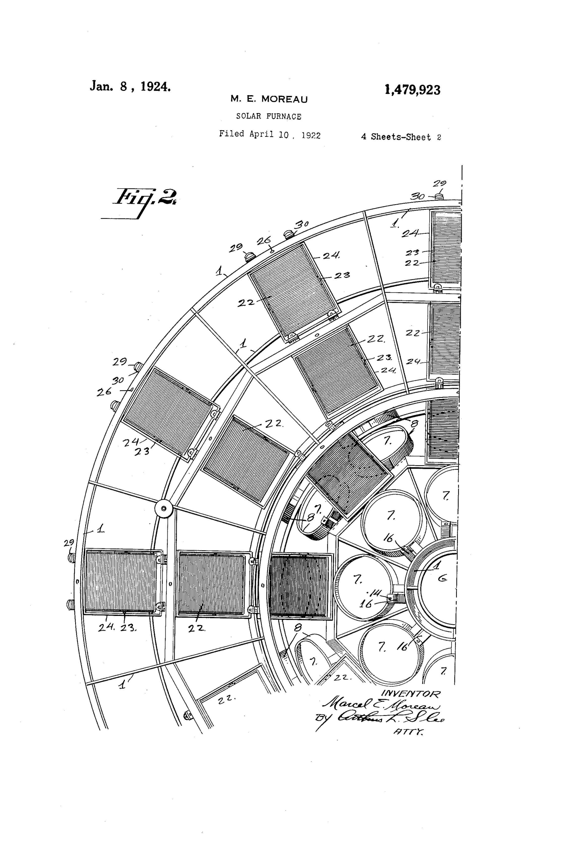
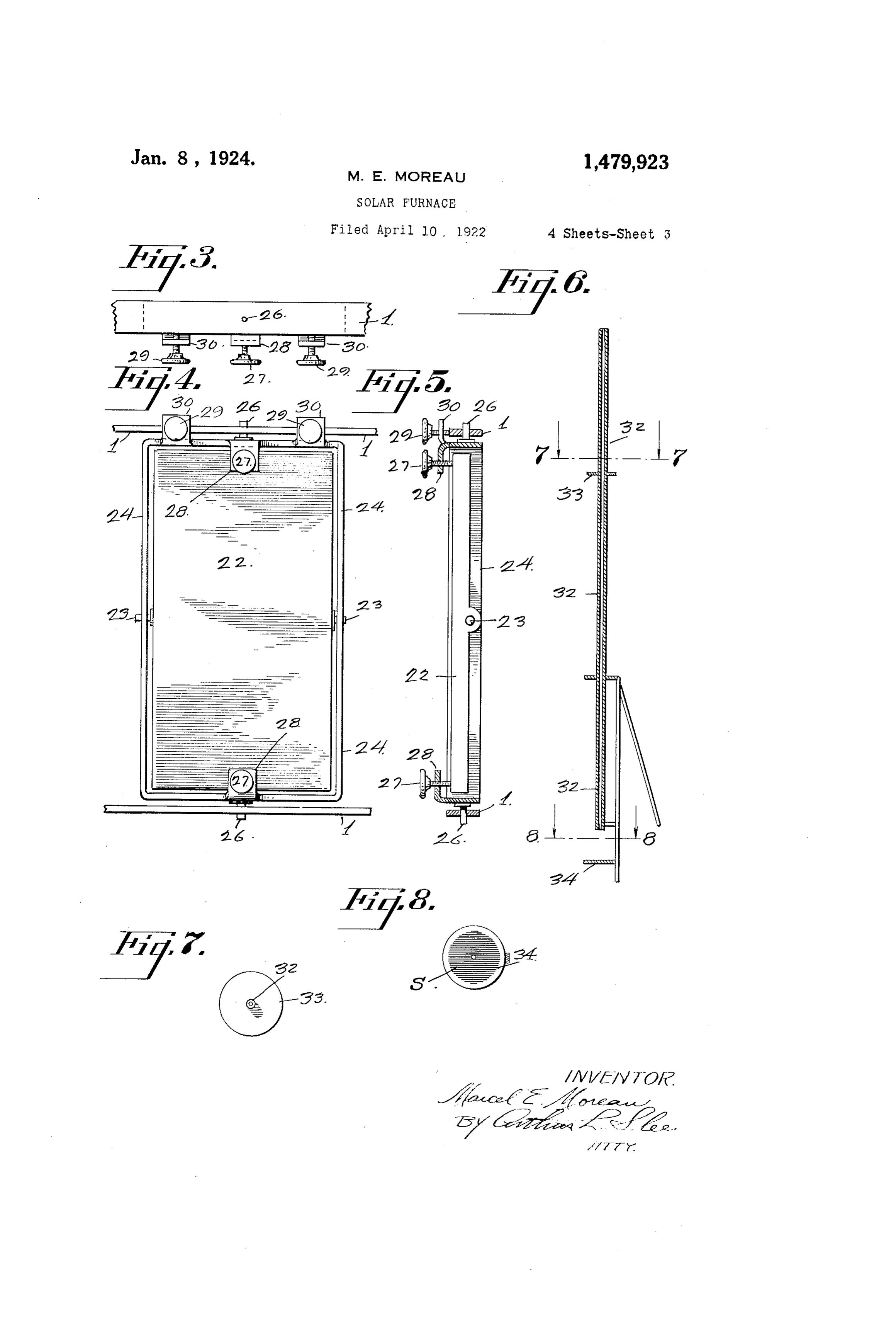
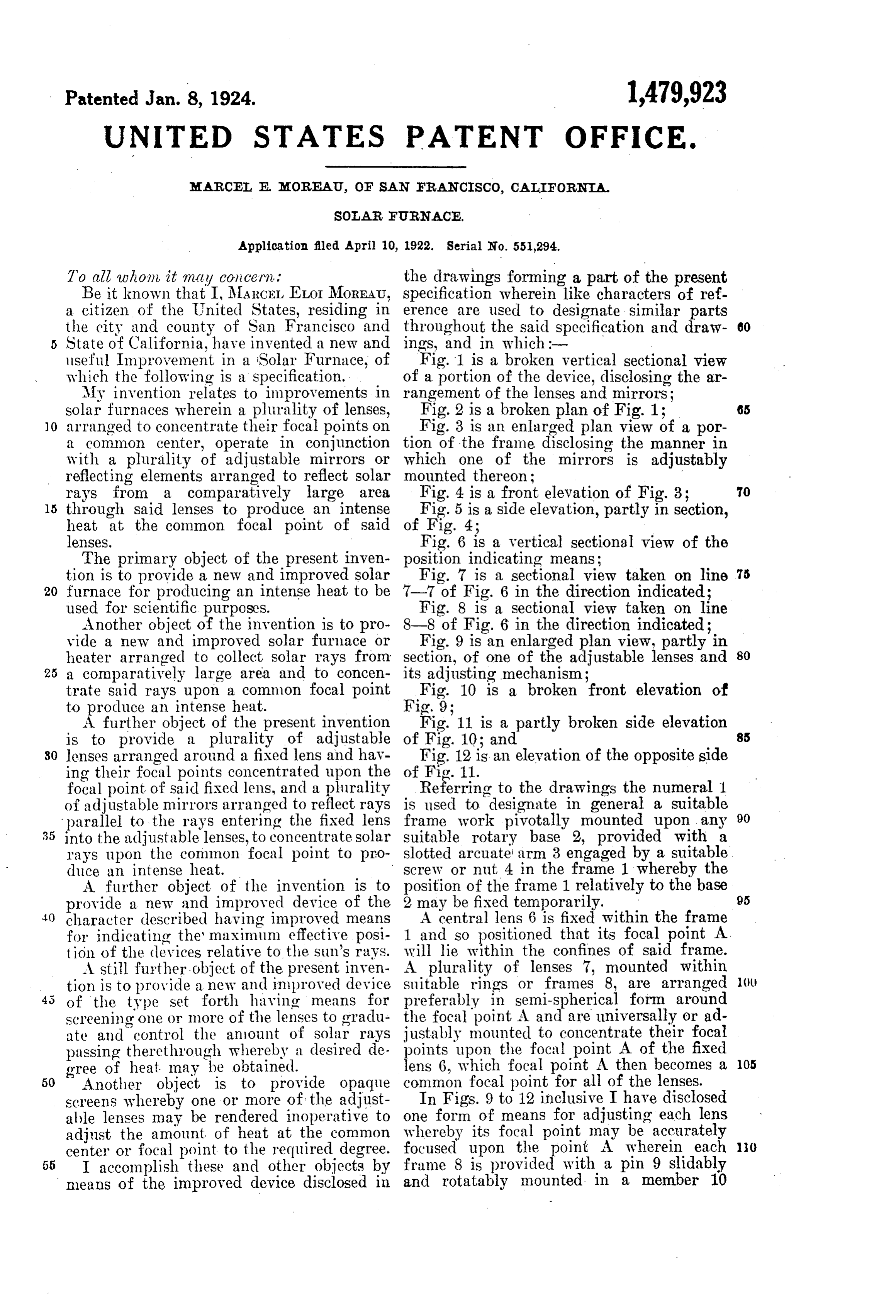
To all whom it may concern. the drawings forming a part of the present Be it known that I, MARCEL ELOI MoREAU, specification wherein like characters of ref a citizen of the United States, residing in erence are used to designate similar parts the city and county of San Francisco and throughout the said specification and draw 60 s State of California, have invented a new and ings, and in which :- useful Improvement in a Solar Furnace, of Fig. 1 is a broken vertical sectional view which the following is a specification. of a portion of the device, disclosing the ar My invention relates to improvements in rangement of the lenses and mirrors; solar furnaces wherein a plurality of lenses, Fig. 2 is a broken plan of Fig. 1; 65 10 arranged to concentrate their focal points on Fig. 3 is an enlarged plan view of a por a common center, operate in conjunction tion of the frame disclosing the manner in with a plurality of adjustable mirrors or which one of the mirrors is adjustably reflecting elements arranged to reflect solar mounted thereon:
rays from a comparatively large area Fig. 4 is a front elevation of Fig. 3; 70 15 through said lenses to produce an intense Fig. 5 is a side elevation, partly in section, heat at the common focal point of Said of Fig. 4;
lenses. Fig. 6 is a vertical sectional view of the The primary object of the present inven position indicating means;
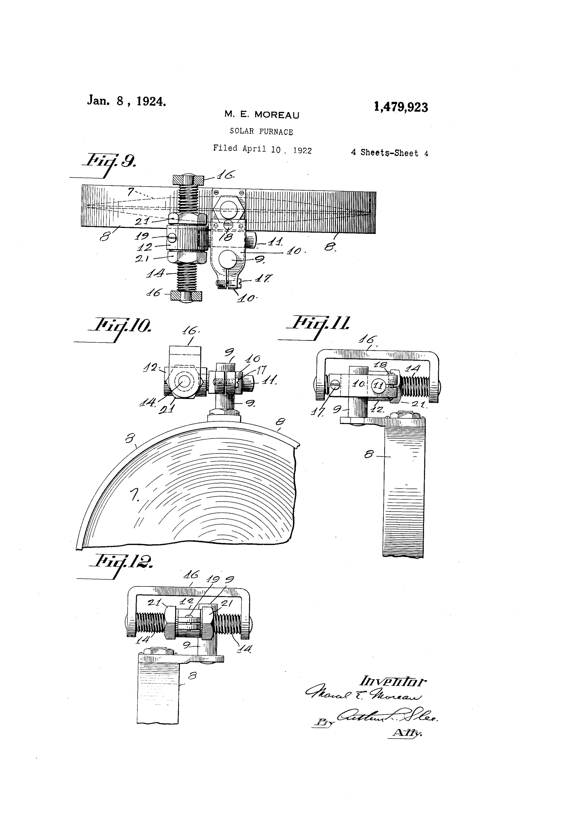
tion is to provide a new and improved solar Fig. 7 is a sectional view taken on line 75 20 furnace for producing an intense heat to be 7-7 of Fig. 6 in the direction indicated; used for scientific purposes. Fig. 8 is a sectional view taken on line Another object of the invention is to pro 8-8 of Fig. 6 in the direction indicated; vide a new and improved solar furnace or Fig. 9 is an enlarged plan view, partly in heater arranged to collect solar rays from section, of one of the adjustable lenses and 80 25 a comparatively large area and to concen its adjusting mechanism;
trate said rays upon a common focal point Fig. 10 is a broken front elevation of
A further object of the present invention Fig. 11 is a partly broken side elevation is to provide a plurality of adjustable of Fig. 10; and 30 lenses arranged around a fixed lens and hav Fig. 12 is an elevation of the opposite side ing their focal points concentrated upon the of Fig. 1.
focal point of Said fixed lens, and a plurality Referring to the drawings the numeral 1 of adjustable mirrors arranged to reflect rays is used to designate in general a suitable 90 parallel to the rays entering the fixed lens frame work pivotally mounted upon any 35 into the adjustable lenses, to concentrate Solar suitable rotary base 2, provided with a rays upon the common focal point to pro slotted arcuate arm 3 engaged by a suitable duce an intense heat. screw or nut 4 in the frame 1 whereby the A further object of the invention is to position of the frame 1 relatively to the base 95 provide a new and improved device of the 2 may 40 character described having improved means be fixed temporarily.
A central lens 6 is fixed within the frame for indicating the maximum effective posi 1 and so positioned that its focal point A. tion of the devices relative to the Sun's rays. will lie within the confines of said frame. A still further object of the present inven A plurality of lenses 7, mounted within tion is to provide a new and improved device suitable rings or frames 8, are arranged (t of the type set forth having means for preferably in semi-spherical form around screening one or more of the lenses to gradu the focal point A and are universally or ad ate and control the annount of Solar rays justably mounted to concentrate their focal passing therethrough whereby a desired de points upon the focal point A of the fixed OS gree of heat may be obtained. lens 6, which focal point Athen becomes a 50 Another object is to provide opaque common focal point for all of the lenses. screens whereby one or more of the adjust In Figs. 9 to 12 inclusive I have disclosed one form of means for adjusting each lens able lenses may be rendered inoperative to whereby adjust the amount of heat at the common its focal point may be accurately center or focal point to the required degree. focused upon the point. A wherein each 55 I accomplish these and other objects by frame 8 is provided with a pin 9 slidably means of the improved device disclosed in and rotatably mounted in a member 10
Page 6
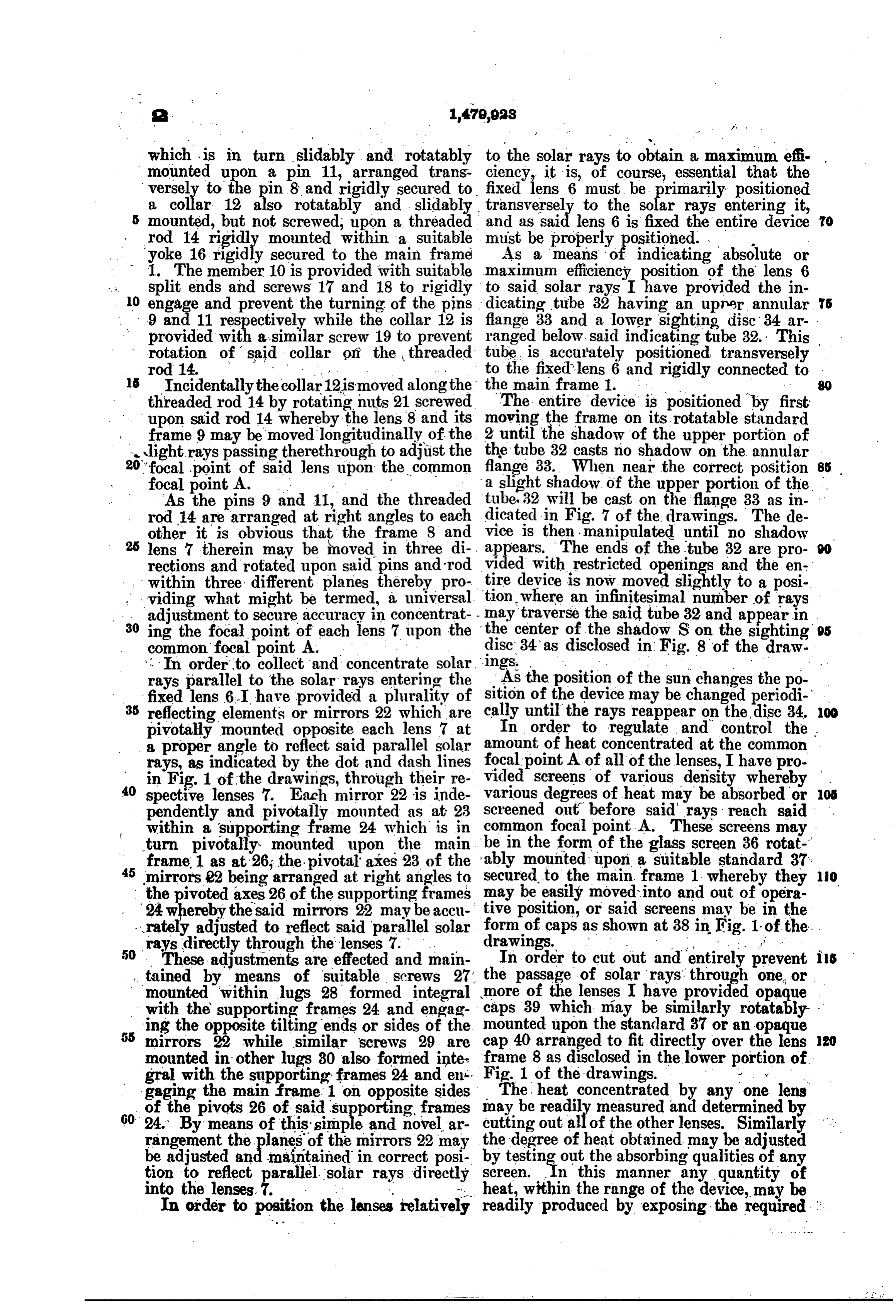
which is in turn slidably and rotatably to the solar rays to obtain a maximum effi- . mounted upon a pin 11, arranged trans ciency, it is, of course, essential that the versel to the pin8 and rigidly secured to fixed lens 6 must be primarily positioned a collar 12 also rotatably and slidably transversely to the solar rays entering it, mounted, but not screwed, upon a threaded and as said lens 6 is fixed the entire device 70 rod 14 rigid mounted within a suitable must be properly positioned. .
yoke 16 rigi secured to the main frame As a means of indicating absolute or 1. The member 10 is provided with suitable maximum efficiency position of the lens 6 split ends and screws 17 and 18 to rigidly to said solar rays I have provided the in 10 9engage and prevent the turning of the pins dicating tube 32 having an upner annular 75 and 11 respectively while the collar 12 is flange 33 and a lower sighting disc 34 ar- . provided with a similar screw 19 to prevent ranged below. said indicating tube 32. This rotation of saidw collar pn the threaded tube, is accurately positioned transversely rod 14. to the fixed lens 6 and rigidly connected to 15 Incidentally the collar 12is moved along the the main frame 1. . .. - - threaded rod 14 by rotating nuts 21 screwed The entire device is positioned by first upon said rod 14 whereby the lens 8 and its moving the frame on its rotatable standard frame 9 may be moved longitudinally of the 2 until the shadow of the upper portion of Jight rays passing therethrough to adjust the the tube 32 casts no shadow on the annular flange 33. When near the correct position 85 20 'focal point of focal point A. . .
said lens upon the
common a slight shadow of the upper portion of the .
As the pins 9 and 11, and the threaded tube, 32 will be cast on the flange 33 as in rod 14 are arranged at right angles to each dicated in Fig. 7 of the drawings. The de other it is obvious that the frame 8 and vice is then manipulated until no shadow lens 7 therein may be moved in three di appears. The ends of the tube 32 are pro rections and rotated upon said pins and rod vided with restricted openings and the en within three different planes, thereby pro tire device is now moved slightly to a posi viding what might be termed, a universal tion where an infinitesimal number of rays 30 ing the focalto point adjustment secure accuracy in concentrat lay traverse the said tube 32 and appearin of each lens 7 upon the discthe center of the shadow S on the sighting 95 common focal point A. 34 as disclosed in Fig. 8 of the draw. . . In order to collect and concentrate solar. 'ings.
rays parallel to the solar rays entering the As the position of the sun changes the po : fixed lens 6...I have provided a plurality of sition of the device may be changed periodi 35 reflecting elements or mirrors 22 which are cally until the rays reappear on the disc 34. 00 pivotally mounted opposite each lens 7 at In order to regulate and control the a proper angle to reflect said parallel solar amount of heat concentrated at the common. rays, as indicated by the dot and dashlines vided focal point A of all of the lenses, I have pro in Fig. 1 of the drawings, through their re screens of various density whereby 40 spective lenses 7. Each mirror 22 is inde various degrees of heat may be absorbed or iOS pendently and pivotally mounted as at 23 Screened out before said rays reach said . within a supporting frame 24 which is in common focal point A. These screens may turn pivotally mounted upon the main. be in the form of the glass screen 36 rota frame 1 as at 26; the pivotal axes 23 of the ably mounted upon a suitable standard 37. 45 mirrors 22 being arranged at right angles to secured to the main frame 1 whereby they
the pivoted axes 26 of the supporting frames may be easily moved into and out of opera 24 whereby the said mirrors 22 may be accu tive position, or said screens may be in the rately adjusted to reflect said parallel solar drawings.
form of caps as shown at 38 in Fig. 1 of the rays directly through the lenses, 50 - These adjustments are effected and main
In order to cut out and entirely prevent i5 , tained by means of suitable screws 2. the passage of solar rays through one or mounted within lugs 28 formed integral more of the lenses I have provided opaque with the supporting frames 24 and engag caps 39 which may be similarly rotatably ing 55 mirrors the opposite tilting ends or sides of the mounted upon the standard 37 or an opaque 22 while similar screws 29 are cap 40 arranged to fit directly over the lens 20 mounted in other lugs 30 also formed inte frame 8 as disclosed in the lower portion of
gral with the supporting frames 24 and en gaging the main frame 1 on opposite sides The heat concentrated by any one lens of the pivots 26 of said supporting, frames may be readily measured and determined by 60 24. By means of this simple and novel ar cutting out all of the other lenses. Similarly ". rangement the E. of the mirrors 22 may the degree of heat obtained may be adjusted be adjusted and maintained in correct posi by sing out the absorbing qualities of any tion to reflect parallel solar rays directly screen. In this manner any quantity of into the lenses. - . - heat, within the range of the device, may be In order to position the lenses relatively readily produced by exposing the required
Page 7
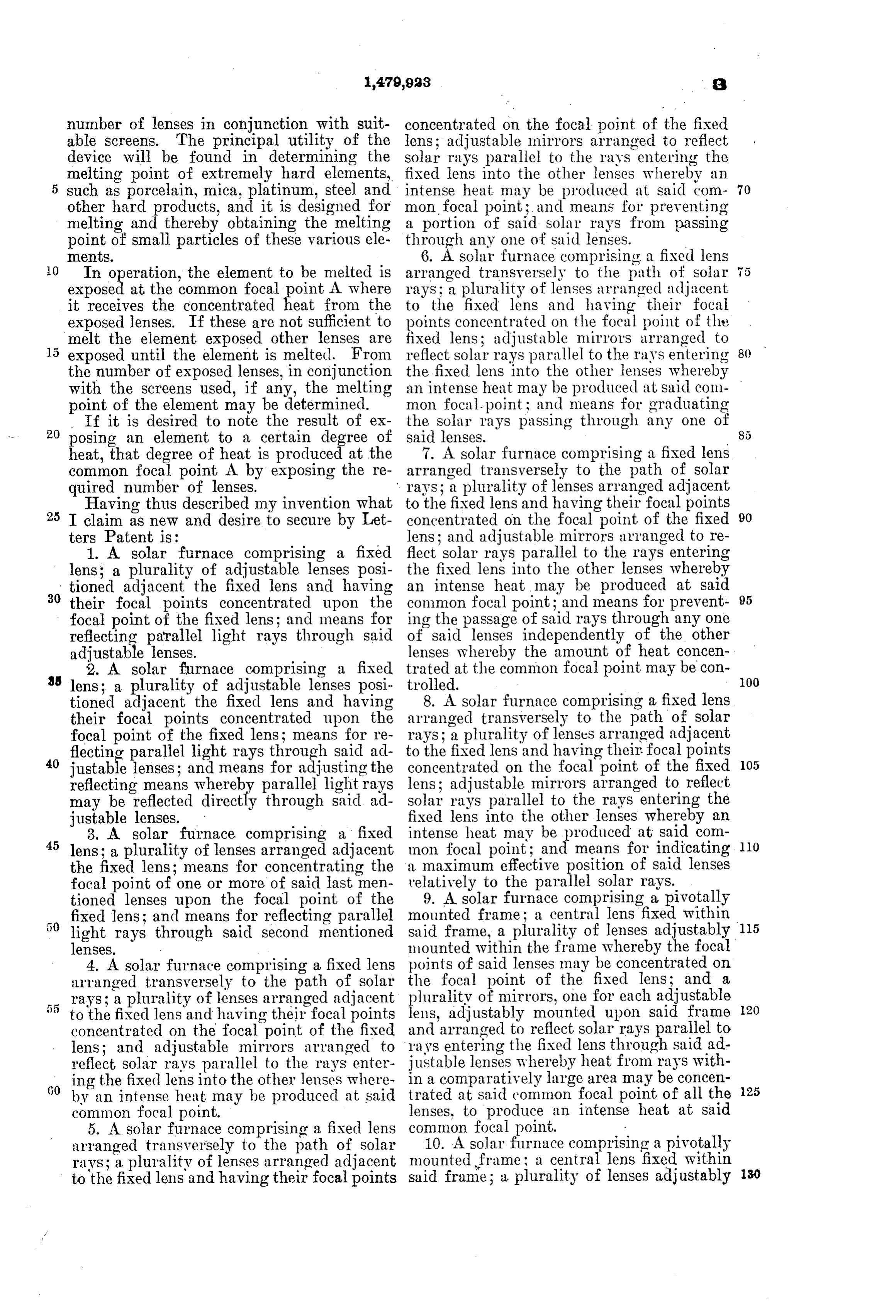
number of lenses in conjunction with suit concentrated on the focal point of the fixed able screens. The principal utility of the lens; adjustable mirrors arranged to reflect device will be found in determining the solar rays parallel to the rays entering the melting point of extremely hard elements, fixed lens into the other lenses whereby an such as porcelain, mica, platinum, steel and intense heat may be produced at said com 70 other hard products, and it is designed for mon focal point; and means for preventing melting and thereby obtaining the melting a portion of said Solar rays from passing point of small particles of these various ele through any one of said lenses. mentS. 6. A solar furnace comprising a fixed lens O In operation, the element to be melted is arranged transversely to the path of solar 5 exposed at the common focal point A where rays; a plurality of lenses arranged adjacent it receives the concentrated heat from the to the fixed lens and having their focal exposed lenses. If these are not sufficient to points concentrated on the focal point of the melt the element exposed other lenses are fixed lens; adjustable mirrors arranged to exposed until the element is melted. From reflect solar rays parallel to the rays entering the number of exposed lenses, in conjunction the fixed lens into the other lenses whereby with the screens used, if any, the melting an intense heat may be produced at said com point of the element may be determined. mon focal-point; and means for graduating If it is desired to note the result of ex the Solar rays passing through any one of 20 posing an element to a certain degree of said lenses.
heat, that degree of heat is produced at the 7. A solar furnace comprising a fixed lens common focal point A by exposing the re arranged transversely to the path of solar quired number of lenses. rays; a plurality of lenses arranged adjacent Having thus described my invention what to the fixed lens and having their focal points
I claim as new and desire to secure by Let concentrated on the focal point of the fixed 90 ters Patent is: lens; and adjustable mirrors arranged to re 1. A solar furnace comprising a fixed flect solar rays parallel to the rays entering lens; a plurality of adjustable lenses posi the fixed lens into the other lenses whereby tioned adjacent the fixed lens and having an intense heat may be produced at Said 30 their focal points concentrated upon the common focal point; and means for prevent 95 focal point of the fixed lens; and means for ing the passage of said rays through any one reflecting parallel light rays through said of said lenses independently of the other adjustable lenses. lenses whereby the amount of heat concen 2. A solar furnace comprising a fixed trated 3. lens; a plurality of adjustable lenses posi trolled.
at the common focal point may be con 00 tioned adjacent the fixed lens and having 8. A solar furnace comprising a fixed lens their focal points concentrated upon the arranged transversely to the path of Solar focal point of the fixed lens; means for re rays; a plurality of lenses arranged adjacent flecting parallel light rays through said ad to the fixed lens and having their focal points
justable lenses; and means for adjusting the concentrated on the focal point of the fixed 105 reflecting means whereby parallel light rays lens; adjustable mirrors arranged to reflect may be reflected directly through said ad solar rays parallel to the rays entering the justable lenses. fixed lens into the other lenses whereby an 3. A solar furnace comprising a fixed intense heat may be produced at said com 45 lens; a plurality of lenses arranged adjacent mon focal point; and means for indicating 10 the fixed lens; means for concentrating the a maximum effective position of Said lenses focal point of one or more of said last men relatively to the parallel Solar rays. tioned lenses upon the focal point of the 9. A solar furnace comprising a pivotally fixed lens; and means for reflecting parallel mounted frame; a central lens fixed within 115 light rays through said second mentioned said frame, a plurality of lenses adjustably lenses. mounted within the frame whereby the focal 4. A solar furnace comprising a fixed lens points of said lenses may be concentrated on arranged transversely to the path of solar the focal point of the fixed lens; and a rays; a plurality of lenses arranged adjacent plurality of mirrors, one for each adjustable to the fixed lens and having their focal points lens, adjustably mounted upon said frame 20 concentrated on the focal point of the fixed and arranged to reflect solar rays parallel to lens; and adjustable mirrors arranged to rays entering the fixed lens through said ad reflect solar rays parallel to the rays enter justable lenses whereby heat from rays with ing the fixed lens into the other lenses where in a comparatively large area may be concen by an intense heat may be produced at said trated at said common focal point of all the 25 common focal point. lenses, to produce an intense heat at said 5. A solar furnace comprising a fixed lens common focal point.
arranged transversely to the path of Solar 10. A solar furnace comprising a pivotally rays; a plurality of lenses arranged adjacent mounted frame a central lens fixed within to the fixed lens and having their focal points said frame; a plurality of lenses adjustably 30
Page 8
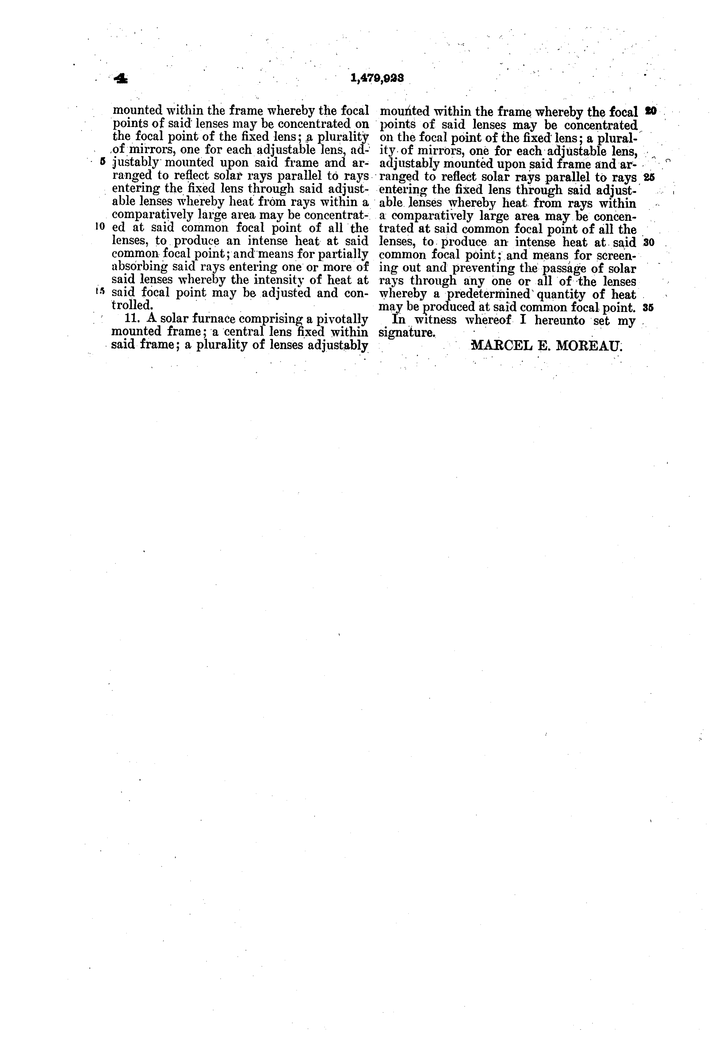
mounted within the frame whereby the focal mounted within the frame whereby the focal to points of said lenses may be concentrated on points of said lenses may be concentrated the focal point of the fixed lens; a plurality on the focal point of the fixed lens; a plural of mirrors, one for each adjustable lens, ad ity of mirrors, one for each adjustable lens, justably mounted upon said frame and ar adjustably mounted upon said frame and ar ranged to reflect solar rays parallel to rays. ranged to reflect solar rays parallel to rays entering the fixed lens through said adjust entering the fixed lens through said adjust able lenses whereby heat from rays within a able lenses whereby heat from rays within comparatively large area may be concentrat a comparatively large area may be concen 0. ed at said common focal point of all the trated at said common focal point of all the lenses, to produce an intense heat at said lenses, to produce an intense heat at. said 30 common focal point; and means for partially common focal point; and means for screen absorbing said rays entering one or more of ing out and preventing the passage of Solar said lenses whereby the intensity of heat at rays through any one or all of the lenses 5 said focal point may be adjusted and con trolled. whereby E. at said common focalofpoint. heat 35 11. A solar furnace comprising a pivotally may be produced
In witness whereof. I hereunto set my mounted frame; a central lens fixed within signature.
said frame; a plurality of lenses adjustably MARCEL E. MOREAU.
Provenance
- Collection
- Cited prior art
- Original PDF
- patentimages.storage.googleapis.com →
- Filed
- 1922-04-10
- Pages
- 8
- Method
- pdftotext (the PDF's own text layer) + pdftoppm 300dpi page scans
- Source
- Google Patents bibliographic record
- Granted
- 1924-01-08
- Inventors
- Marcel E Moreau
- Transcribed from
- patentimages.storage.googleapis.com →