patent · US1081098
Solar-heating apparatus.
9 December 1913
Page 1
M. DE LA GARZA,
SOLAR HEATING APPARATUS,
APPLICATION FILED J AN. 18, 1913.
1,081,098. Patented Dec. 9, 1913.
3. SS 4. i? Z. A2 40c.
asses zazel2
WITNESSES Marcos de la Garzo
*2, AT TORNEKS
Page 2
UNITED STATES PATENT OFFICE.
AARCOS DE LA GARZA, OF ET, PASO, TEXAS.
soLAR-HEATING APPARATUS, 1,081,098. Specialeation of Letters Patent, Patented Dec. 9, 1913. Application fled January 18, 1913. Serial No. 742,819.
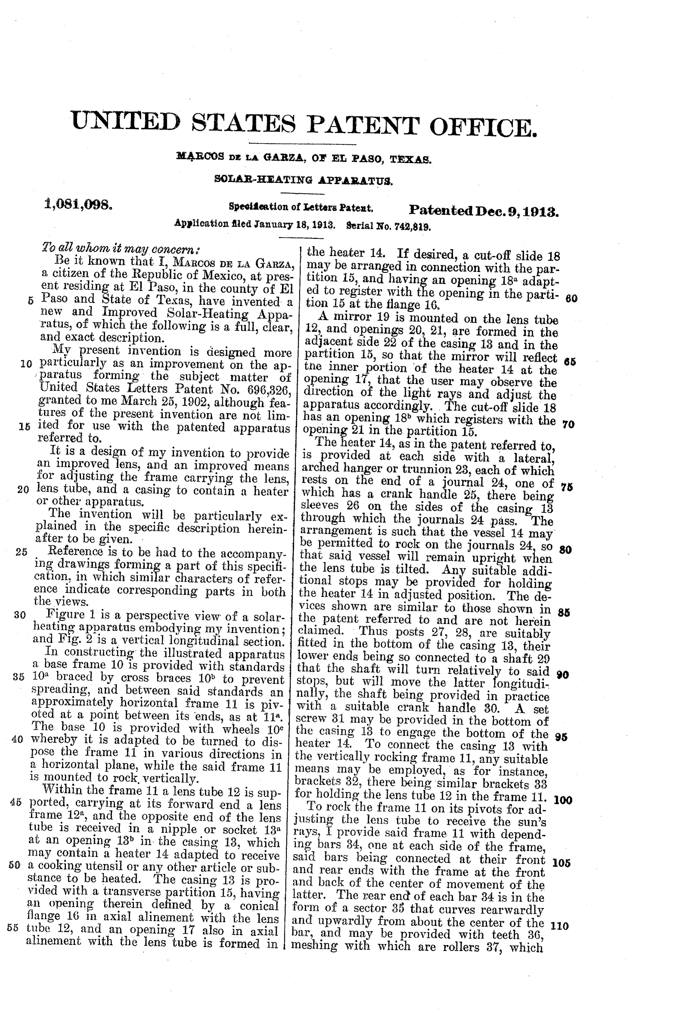
To all whom it may concern the heater 14. If desired, a cut-off slide 18 Be it known that , MARcos DE LA GARZA, may a citizen of the Republic of Mexico, at pres titionbe15,arranged in connection with the par ent residing at El Paso, in the county of El ed to register with theanopening and having opening 18 adapt in the parti 80
Paso and State of Texas, have invented a tion 15 at the flange 16.
new and Improved Solar-Heating AE ratus, of which the following is a full, c ear, 12,Aand mirror 19 is mounted on the lens tube and exact description. openings 20, 21, are formed in the My present invention is designed more partition side adjacent
22 of the casing 13 and in the so that the mirror will reflect 65 0. particularly as an improvement on the ap the inner ; paratus forming the subject matter of opening 17, that the portion of the heater 14 at the United States Letters Patent No. 696,326, direction of the lightuser may observe the granted to me. March 25, 1902, although fea apparatus accordingly. The and rays adjust the cut-off slide 18 tures of the present invention are not lim has an opening 18 which registers with 5 ited for use with the patented apparatus opening the 70 referred to. 21 in the partition 15. It is a design of my invention to provide is The heater 14, as in the patent referred to, provided at each side with a lateral, an improved lens, and an improved means arched for adjusting the frame carrying the lens, rests onhanger the or trunnion 28, each of which end of a journal 24, one of 20 lens tube, and a casing to contain a heater or other apparatus. which has a crank handle 25, there being sleeves 26 on
The invention will be particularly ex through which the journals the sides of the casing 13 plained in the specific description herein arrangement is such that the 24 pass. The vessel 14 may after to be given.
25 Reference is to be had to the accompany that said vessel will remain upright 24, be permitted to rock on the journals when
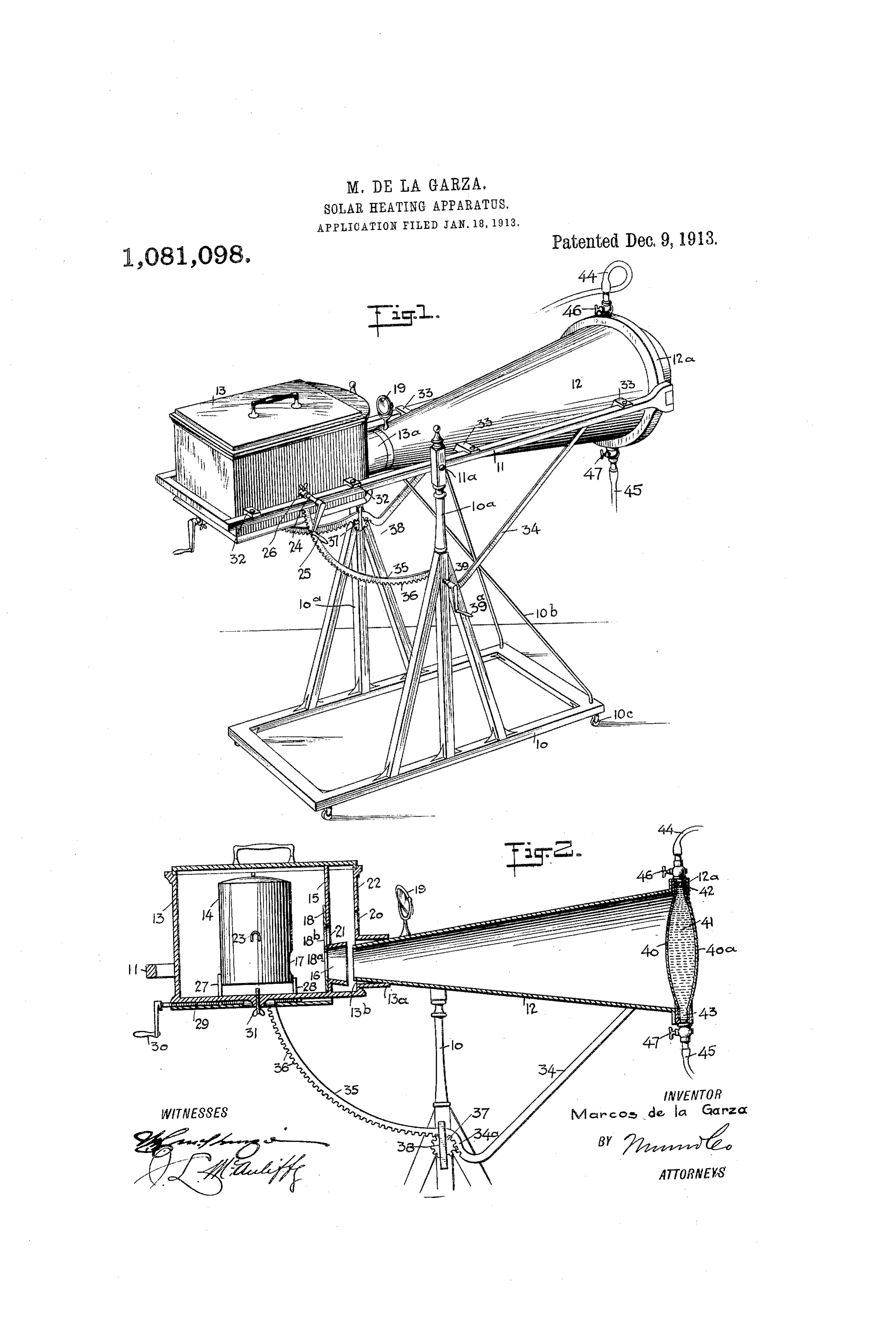
ing drawings forming a part of this specifi cation, in which E. characters of refer the lens tube is tilted. Any suitable addi tional stops may be provided for holding ence indicate corresponding parts in both the heater the views. 14 in adjusted position. The de vices shown are similar to those shown in 85 30 Figure 1 is a perspective view of a solar the patent referred heating apparatus embodying my invention; claimed. Thus poststo 27, and are not herein 28, are suitably and Fig. 2 is a vertical longitudinal section. fitted
In constructing the illustrated apparatus lower ends being so connectedcasing
a base frame 10 is provided with standards that the shaft will turn relatively shaft 35 10 braced by cross braces 10 to prevent
to said 90 spreading, and between said standards an nally, stops, but will move the latter longitudi approximately horizontal frame 11 is piv with athesuitable shaft being provided in practice crank handle 30. A set oted at a point between its ends, as at 11. screw 31 may be provided in the bottom of The base 10 is provided with wheels 10° 40 whereby it is adapted to be turned to dis the casing 18 to engage the bottom of the 95 pose the frame 11 in various directions in the heater 14. To connect the casing 13 with a horizontal plane, while the said frame 11 means vertically rocking frame 11, any suitable is mounted to rock, vertically. may be employed, as for instance, Within the frame 11 a lens tube 12 is sup brackets 32, there being similar brackets 33 45 ported, carrying at its forward end a lens for holding the lens tube 12 in the frame 11. OO frame 12", and the opposite end of the lens justing To rock the frame 11 on its pivots for ad tube is received in a nipple or socket 13 rays, I provide the lens tube to receive the sun's at an opening 13 in the casing 13, which ing bars 34, onesaid at frame 11 with depend each side of the frame, may contain a heater 14 adapted to receive 50 a cooking utensil or any other article or sub said bars being connected at their front 105 and rear ends with the frame at the front stance to be heated. The casing 13 is pro and back of the center of movement of the vided with a transverse partition 15, having an opening therein iA by a conical latter. The rear end of each bar 34 is in the form of a sector 35 that curves rearwardly flange 16 in axial alinement with the lens 55 tube 12, and an opening 17 also in axial and upwardly from about the center of the O alinement with the lens tube is formed in bar, and may be provided with teeth 36, meshing with which are rollers 37, which
Page 3
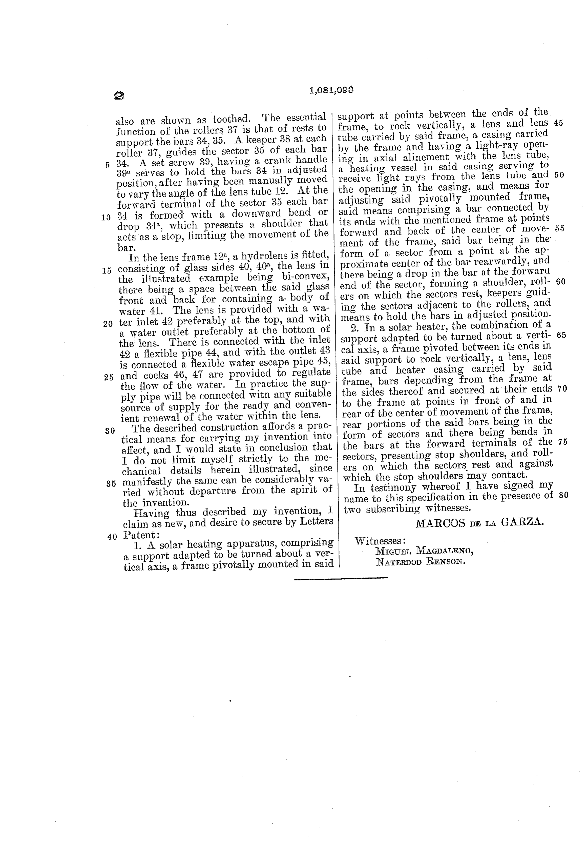
also are shown as toothed. The essential support at points between the ends of the 45 function of the rollers 37 is that of rests to frame, to rock vertically, a lens and lens support the bars 34,35. A keeper 38 at each tube carried by said frame, a casing carried roller 37, guides the sector 35 of each bar ing in frame by the axial and having a light-ray open alinement with the lens tube, 5 34. A set screw 39, having a crank handle a heating vessel in Said casing serving to 39 serves to hold the bars 34 in adjusted receive light rays from the lens tube and 50 position, after having been manually moved the opening in the casing, and means for to vary the angle of the lens tube 12. At the adjusting said pivotally mounted frame, forward terminal of the sector 35 each bar 0 34 is formed with a downward bend or said means comprising a bar connected by drop 34, which presents a shoulder that its ends with the mentioned frame at points 55 as a stop, limiting the movement of the ment of and forward the back of the center of move frame, said bar being in the
form of a sector from a point at the ap
In the lens frame 12, a hydrolens is fitted, proximate center of the barrearwardly, 15 consisting of glass sides 40, 40, the lens in there being a drop in the bar at the forward and the illustrated example being bi-convex, of the sector, forming a shoulder, roll 60 there being a space between the said glass end front and back for containing a body of ing thewhich ers on the sectors rest, keepers guid sectors adjacent to the rollers, and water 41. The lens is provided with a wa means to hold the bars in adjusted position. 20 ter inlet 42 preferably at the top, and with 2. In a solar heater, the combination of a 65 a water outlet preferably at the bottom of the lens. There is connected with the inlet support adapted to be turned about a verti cal axis, a frame pivoted between its ends in 42 a flexible pipe 44, and with the outlet 43 said is connected a flexible water escape pipe 45, tube support and to rock vertically, a lens, lens heater casing carried by said 25 and cocks 46, 47 are provided to regulate frame, bars depending from the frame at 70 the flow of the water. In practice the sup the sides thereof and secured at their ends ply pipe will be connected witn any suitable to the frame at points in front of and in source of supply for the ready and conven rear of the center of movement of the frame, ient renewal of the water within the lens.
30 The described construction affords a prac rear portions of the said bars being in the tical means for carrying my invention into form of sectors and there being bends in the bars at the forward terminals of the 75 effect, and I would state in conclusion that sectors, presenting stop shoulders, and roll I do not limit myself strictly to the me ers on which the sectors rest and against chanical details herein illustrated, since which the stop shoulders may contact. 35 manifestly the same can be considerably va In testimony whereof I have signed my 80 ried without departure from the spirit of name to this specification in the presence of the invention.
Having thus described my invention, I two subscribing witnesses.
claim as new, and desire to secure by Letters MARCOS DE LA GARZA.
40 Patent:
1. A Solar heating apparatus, comprising Witnesses:
a support adapted to be turned about a ver MIGUET, MAGDALENO,
NATERDoD RENSON.
tical axis, a frame pivotally mounted in said
Provenance
- Collection
- Cited prior art
- Original PDF
- patentimages.storage.googleapis.com →
- Filed
- 1913-01-18
- Pages
- 3
- Method
- pdftotext (the PDF's own text layer) + pdftoppm 300dpi page scans
- Source
- Google Patents bibliographic record
- Granted
- 1913-12-09
- Inventors
- Marcos De La Garza
- Transcribed from
- patentimages.storage.googleapis.com →