patent · US4030890
Solar power system
21 June 1977
Page 1 — bibliographic record
United States Patent (19) (11) 4,030,890 Diggs (45) June 21, 1977 54). SOLAR POWER SYSTEM Primary Examiner-Joseph Scovronek Attorney, Agent, or Firm-Shoemaker and Mattare, 76 Inventor: Richard E. Diggs, S. 12A Road, P.O. Ltd.
(22 Filed: Oct. 20, 1975 57 ABSTRACT (21) Appl. No.: 624,409 An apparatus and method for separating hydrogen and 52) U.S. C. ..................................... 23/281; 55/17; oxygen from water molecules. A solar reflecting means 55/456; 60/641; 60/721; 126/271; 165/DIG. reflects solar energy onto a water containing tank to boil water contained therein and form steam. The 6; 423/579; 423/648 R steam is transferred either to a turbine-generator as (51) int. Cl...................... B01D 57/00; B01J 7/00; sembly for producing power, or to a dissociating means C01B 13/00; F24J 3/02 for producing hydrogen and oxygen. The steam in the 58) Field of Search ................. 23/281, 282,277 R, dissociating means is forced to traverse a spiral path 23/252 R; 423/648,579; 250/527; 204/157.1 wherein it undergoes a circular motion to subject it to R; 202/234; 126/270,271; 165/DIG. 6; 55/17, centrifugal force while contacting a heat transfer sur
face. Solar energy is concentrated on the heat transfer 56 References Cited surface and heat in amounts sufficient to raise the tem UNITED STATES PATENTS perature of the steam to the dissociation temperature thereof is transferred thereto. Hydrogen and oxygen 2,372,155 3/1945 Bosch ........................... 165/DIG. 6 are separated from each other by the centrifugal forces, 2,760,920 8/1956 Olsen ............................. 126/270 X and are withdrawn from the dissociating means. An 2,914,915 12/1959 Sziklas et al.................. 165/DIG. 6 electric starter and means for moving solar reflecting 2,993,480 7/1961 Huet ................................ 551456 X means are also disclosed.
3,460,318 8/1969 Creutz ................................... 55/17 3,747,306 7/1973 Wikdahl ............................ 55/17 X 3,901,668 8/1975 Seitzer ................................... 55/16 3,901,669 8/1975 Seitzer ................................... 55/16 10 Claims, 8 Drawing Figures
Vee
Page 2
Drawing sheet — no readable text.
Page 3
Drawing sheet — no readable text.
Page 4
Drawing sheet — no readable text.
Page 5
Drawing sheet — no readable text.
Page 6
which is oriented to receive solar energy reflected by
SOLAR POWER SYSTEM the pivotally mounted solar reflector. The water is
BACKGROUND OF THE INVENTION
heated to the saturation temperature to form steam. A dissociating means is mounted on the housing and re
The present invention relates to separation of hydro 5 ceives steam from the water storage means. The disso gen and oxygen from water, and more particularly, to ciating means includes a bullet-like chamber mounted separation of hydrogen and oxygen from water using on the housing in a location whereat it receives solar solar energy. radiation reflected from the pivotally mounted solar In recent years, advancements in the field of cryogen reflector and from a solar reflecting surface on the ics have resulted in multiplying the number of potential 10 water storage means. A body having a helical flange uses for hydrogen and oxygen in their elemental forms, thereon is located inside the cylindrical housing, and and has consequently increased the demands on exist the steam is introduced at one end of the housing. The ing supplies in these elements. For example, cryogenic steam then is forced to traverse a spiral path wherein it surgery now routinely employs surgical procedures is exposed to the inner surface of the cylindrical hous which were undreamed of a few years ago. Procedures 15 ing, while the solar radiation is reflected upon the outer utilized in preserving perishable items have also em surface of the cylindrical housing so that the tempera ployed cyrogenic fluids. Furthermore, it is even possi ture of the steam is raised to the dissociation tempera ble to fuel automobiles or other vehicles with liquid ture thereof. A gas chamber is connected to the dissoci hydrogen. The liquid forms of both hydrogen and oxy ating means and receives the dissociated hydrogen and gen have also been used in the field of rocket and jet 20 oxygen. Withdrawal means, such as pipes, or the like, propulsion. are connected to the gas chamber for removing the Water is an abundant source of hydrogen and oxy hydrogen and oxygen from the separating means. gen. However, because of the large bonding energies The solar energy is focused on the separating means involved, efficient production of hydrogen and/or oxy by the solar reflector, and that solar energy is used to gen from water through dissociation or separation of 25 boil the water and to dissociate the steam formed by hydrogen and oxygen from a water molecule is often the boiling water. Some of the solar energy is reflected prohibited. twice, and some falls directly on the dissociating The problems involved in the production of hydrogen means. The dissociating means receives both that solar and oxygen from water, is just one of the areas which energy directly incident thereon and that solar energy has been affected by the steadily decreasing supplies of 30 which has been twice reflected. The evaporator re hydrocarbon fuels. In fact, the entire field of power ceives only solar energy reflected from the pivotally. generation has been severly affected by this shortage. mounted solar reflector.
Therefore, the supplies of hydrogen and oxygen are Therefore, the evaporator transfers only enough en being squeezed from both ends, that is, greater de ergy to the water to boil the water and form steam, mands are being placed on the supplies while means for 35 while the double source of solar energy incident upon increasing the supplies are inhibited by the shortage of the dissociation means supplies enough energy to that available power sources. means to raise the temperature of the steam therein to Separation of hydrogen and oxygen from water at the dissociation temperature.
present generally occurs in devices using an electric Furthermore, the helically shaped body within the discharge device or a combustion reaction. These de 40 dissociating means forces the gas in the dissociating vices, therefore, either directly or indirectly are depen means to traverse a spiral path through that dissociat dent upon hydrocarbon fuel as an energy source. Fur ing means. Therefore, dissociated hydrogen and oxy thermore, the energy source is inefficiently used as it is gen are forced to traverse a spiral path, and are there almost totally consumed in the dissociation process. fore subjected to centrifugal forces, from the entrance Therefore, energy sources used to power the dissocia 45 of the dissociating means to the exit thereof. The oxy tion devices are capable of sustaining only the dissocia gen, being heavier then the hydrogen, therefore moves tion reaction, and are therefore inefficiently used. radially outward while forcing the hydrogen radially The present invention uses solar energy as a power inward on the spiral path. The hydrogen and oxygen source for transforming water into steam and for disso withdrawal means are located in the gas chamber so ciating that steam into hydrogen and oxygen. 50 that the hydrogen withdrawal means is located nearer
SUMMARY OF THE INVENTION
the center of the spiral path than is the oxygen with drawal means. Therefore, hydrogen moves into the
The device of the present invention utilizes solar hydrogen withdrawal means, and oxygen moves into energy to transform water into steam through boiling the oxygen withdrawal means. The withdrawal means and steam into hydrogen and oxygen through dissocia 55 are located so that the hydrogen and oxygen are with tion. Hence, hydrogen and oxygen are dissociated with drawn from the gas chamber before recombination out relying on hydrocarbon fuels, and steam is available thereof.
to drive auxiliary equipment, such as turbines, or the A turbine-generator set is mounted on the carriage like. and connected to the evaporator means to receive The device of the present invention comprises a mov 60 steam therefrom to drive the turbine. Therefore, the able carriage on which a solar reflector is pivotally device of the present invention also serves as a solar mounted. Means on the carriage moves the solar reflec power generating means.
tor so that it is properly oriented with respect to the sun Therefore, the device of the present invention is not to reflect solar energy onto a separating means con dependent upon hydrocarbon fuels to supply the en nected to the solar reflector. The separating means 65 ergy required to dissociate hydrogen and oxygen from comprises a housing mounted on the solar reflector and water molecules. Furthermore, the energy is utilized in having a water storage area in which water is stored and an efficient manner and can therefore be used to drive heated by the transfer of heat from a reflecting surface auxiliary equipment as well as perform the dissociation
Page 7
procedure. Therefore, the supplies of hydrogen and thereby onto separating means 60 to boil the water oxygen in their elemental forms can be increased with therein to form steam. Steam formed in separating out placing larger demands on supplies of hydrocarbon means 60 passes through steam line 64 into either dis fuels, and those fuels can then be utilized for other sociating means injector tube 66 or turbine inlet con purposes. 5 duit 68. Flow of steam in line 64 into either tube 66 or
OBJECTS OF THE INVENTION
conduit 68 is controlled by a check valve (not shown).
Alternatively, a steam manifold can surround the sepa
It is therefore a main object of the present invention rating means 60 and be appropriately connected to the to perform a procedure of dissociating hydrogen and separating means, through valves, or the like, to with oxygen from water molecules which, once started does 10 draw steam for the turbine. Steam injected into dissoci not depend on hydrocarbon fuels. ating means 70 (FIG. 4) is heated by radiant energy Another object of the present invention is to dissoci reflected from mirror 42 to raise the temperature ate hydrogen and oxygen from water molecules in a thereof to the dissociating temperature so that the process wherein steam is generated for driving auxiliary water molecules are dissociated into hydrogen and equipment. 15 oxygen. The hydrogen and oxygen are separated from It is yet a further object of the present invention to each other, and the hydrogen is withdrawn from gas dissociate hydrogen and oxygen from water molecules chamber 74 via hydrogen conduit 76, and the oxygen is in a process wherein a solar reflector is always oriented withdrawn from the gas chamber 74 via oxygen conduit to make the most efficient use of radiant energy from 78. The steam in turbine inlet conduit 68 is transferred the sun. 20 into a turbine 80 comprising the usual turbine mechani
BRIEF DESCRIPTION OF THE DRAWINGS
cal and electrical components, and which drives the generator 82 for producing electrical energy, or the
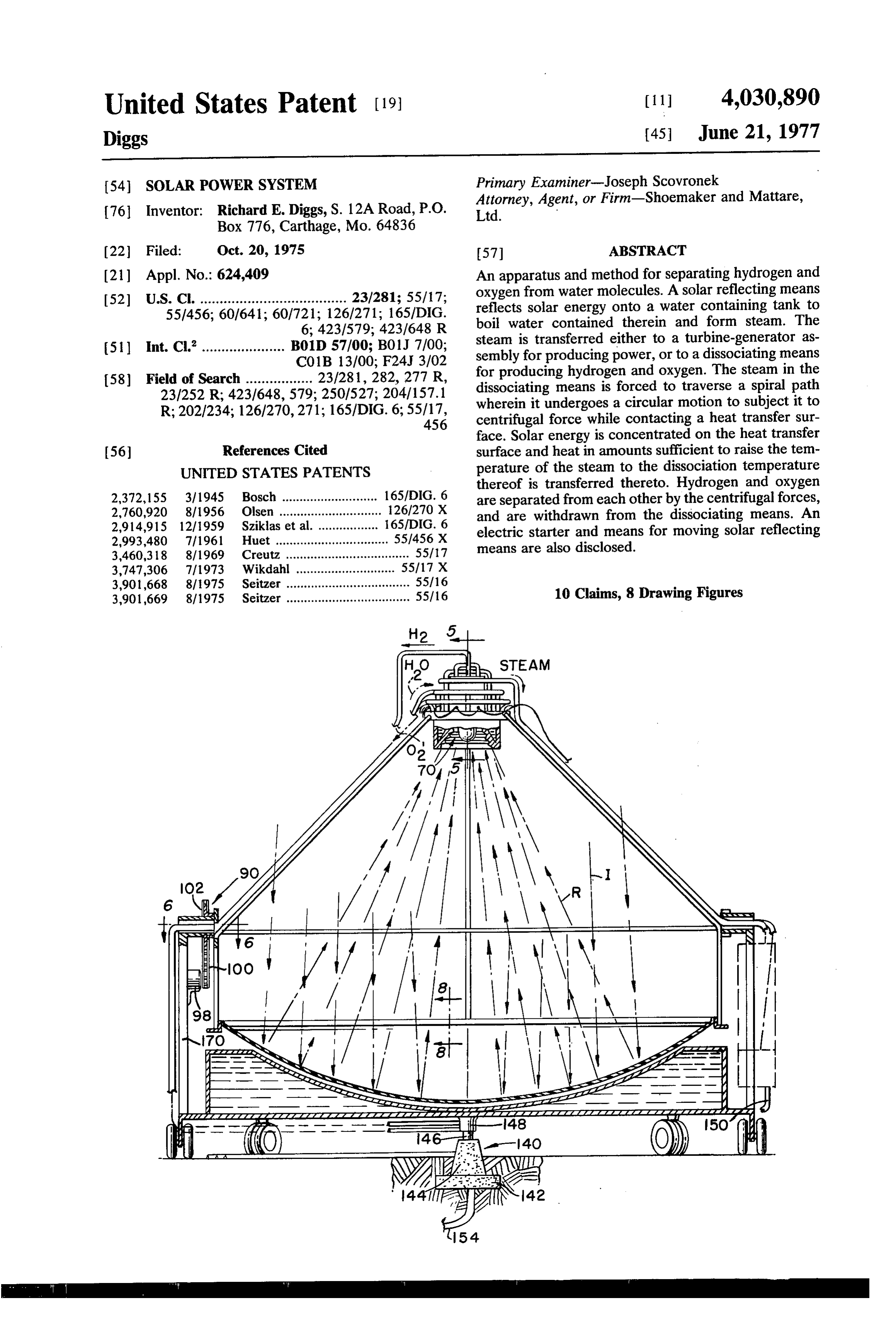
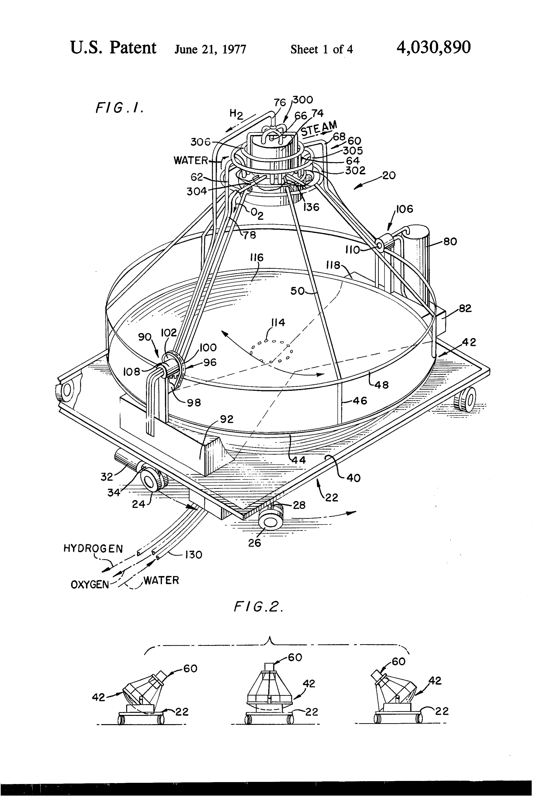
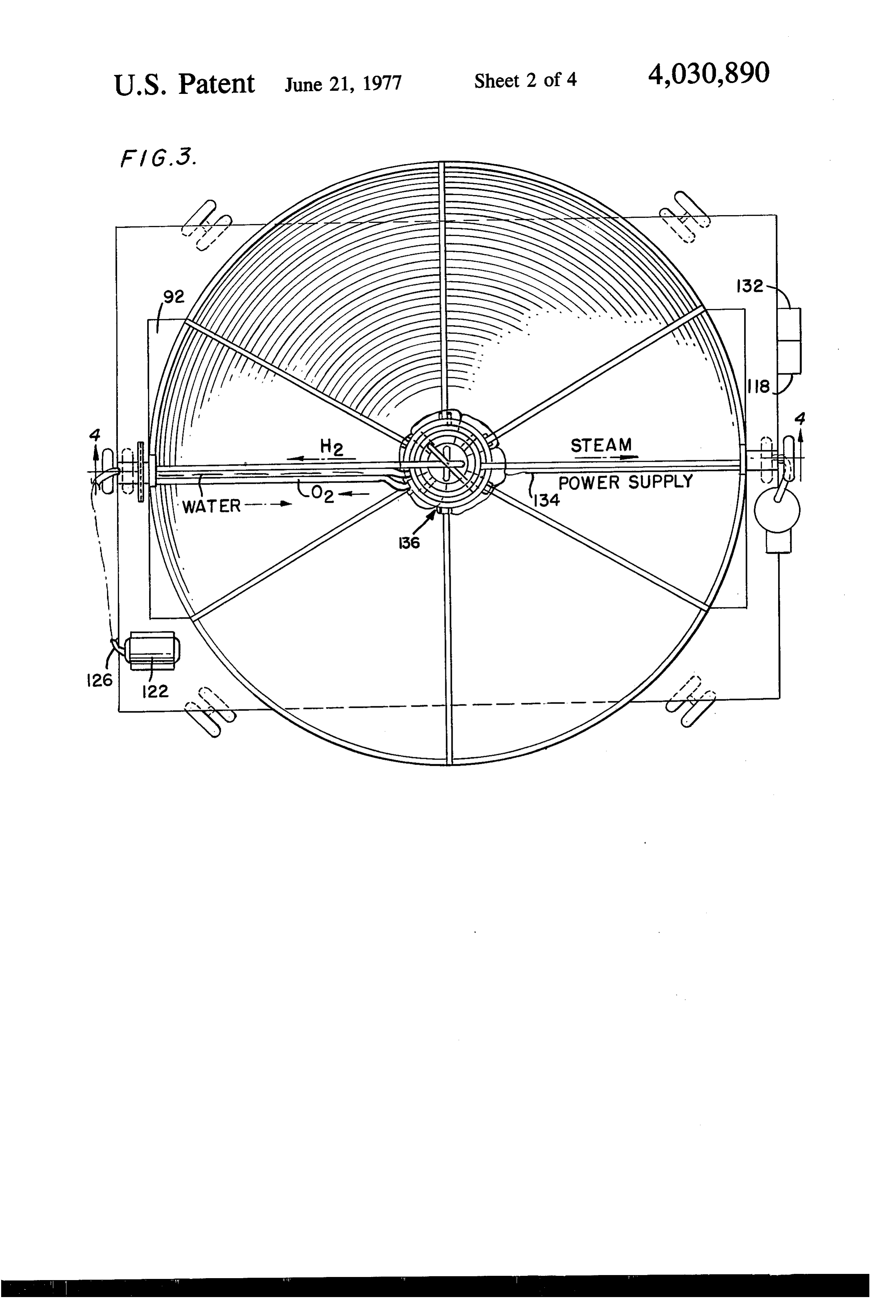
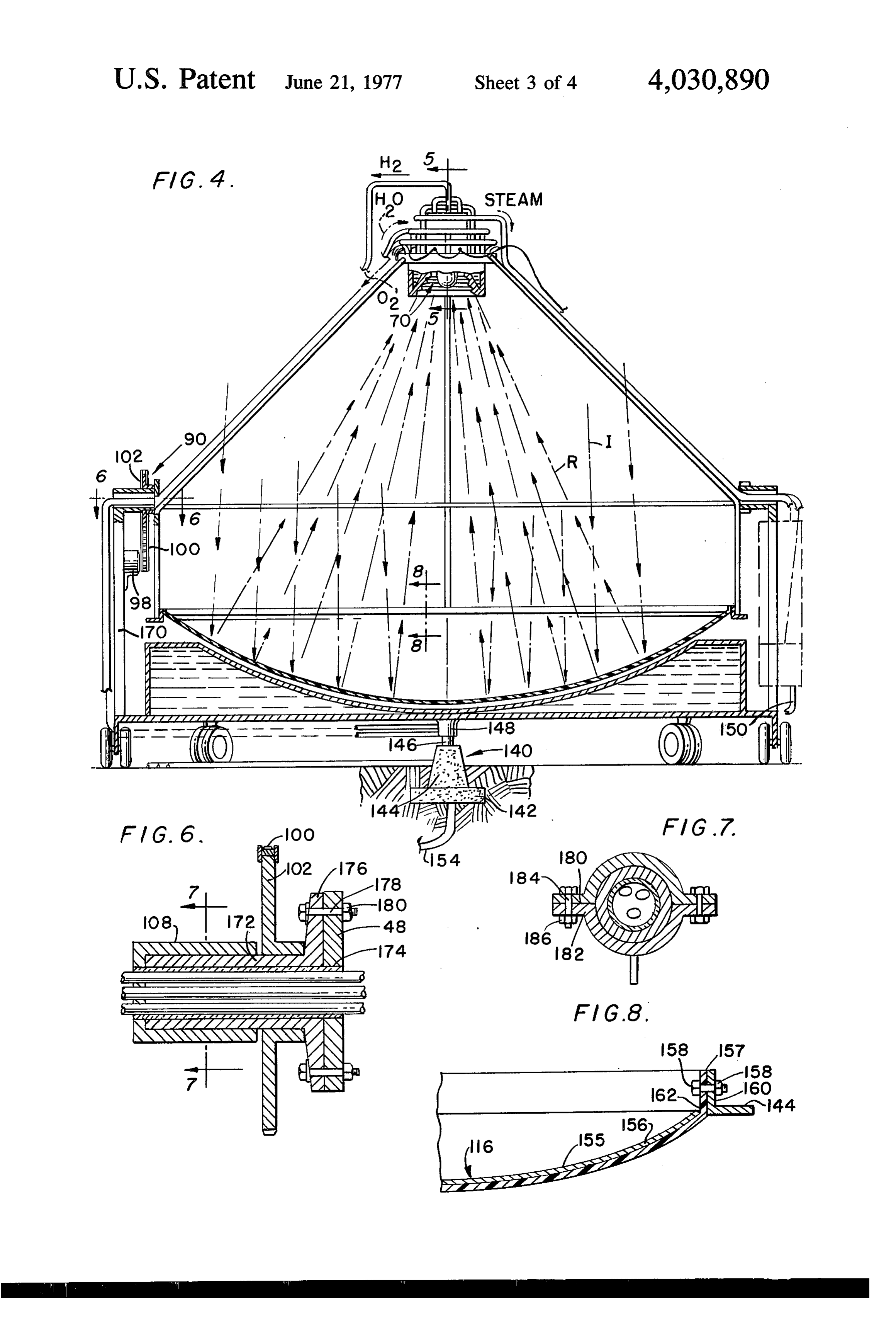
FIG. 1 is a perspective view of the device embodying like.
the teachings of the present invention; Mirror 42 is maintained in an orientation with re FIG. 2 is a schematic view of the device of the pre 25 spect to the sun so that, at any time during daylight sent invention in various attitudes with respect to a hours, the maximum amount of solar energy is re horizontal plane; flected onto separating means 60. Proper orientation of FIG. 3 is a plan view of the device embodying the the mirror and the separating means is effected by teachings of the present invention; movement of the drive wheels 24 by the motors 32 and FIG. 4 is a view in section of FIG.3 and is taken along 30 by pivot means 90 mounted on water storage tank 92 line 4-4 of FIG. 3; and connected to ring 48 of mirror 42 by sprocket FIG. 5 is an enlarged view in section taken along line means 96. A sprocket motor 98 drives a chain 100 5-5 of FIG. 4; which drives a sprocket wheel 102 connected to ring FIG. 6 is an enlarged view in section taken along line 48. A pivot means 106 is also mounted on water stor 6-6 of FIG. 4; 35 age tank 92 and connected to ring 48 so that movement FIG. 7 is an enlarged view in section taken along line of sprocket wheel 102 causes the mirror 42 to pivot 7-7 of FIG. 4; and about an axis through pivot point housings 108 and FIG. 8 is an enlarged view taken in section taken 110. Therefore, the mirror 42 can be pivoted in at least along line 8-8 of FIG. 4. two planes so that it can be properly oriented with 40 respect to the sun.
DETALED DESCRIPTION OF THE PREFERRED A plurality of thermocouples 114 are mounted in the EMBODIMENT mirror uppersurface 116 and are connected to a con Shown in FIG. 1 is an apparatus 20 for separating trol panel 118 located on carriage 40 adjacent mirror hydrogen and oxygen from water molecules. The appa 42. The thermocouples are located on mirror 42 to be ratus 20 comprises a movable carriage 22 having drive 45 in the shadow cast on that mirror by separating means wheels 24 and idler wheels 26 connected to the car 60 when the mirror is properly oriented to reflect inci riage by braces 28 and which are used for placing the dent solar energy onto the separating means 60. As the carriage in a desired orientation. An increment motor earth moves, the shadow cast on mirror surface 116 by 32 is mounted on the undersurface of the carriage and separating means 60 will shift, and eventually uncover is connected to drive wheels 24 by a connecting arm 34 50 one or more of the thermocouples 114. When a ther for moving and adjusting those wheels according to a mocouple is exposed to incident solar energy, the tem predetermined control program. The drive and idler perature of that thermocouple begins to rise, and an wheels are in pairs which are connected by an axle. electrical signal is sent to control panel 118. The con Pivotally mounted on carriage uppersurface 40 is a trol panel 118, in response to the electrical signal sent solar reflecting mirror 42 which has an upper marginal 55 by the thermocouples, operates sprocket motor 98 edge 44 thereon and is shaped in any suitable form, and/or increment motors 32 to reorient mirror 42. The such as parabolic or hyperparabolic. A plurality of reorientation process is continued until all of the ther struts 46 are connected to upper marginal edge 44 and mocouples 114 are in enough of a shadow to lower the extend upwardly therefrom to support a ring 48 in a temperature thereof to levels which indicate that the horizontal orientation with respect to upper marginal 60 mirror is located in the most suitable orientation with edge 44. A plurality of braces 50 are connected to the respect to the sun. A proper control program can be ring 48 and extend upwardly therefrom and radially utilized with control panel 118 to make the proper inward of the mirror 42 toward a focal point of that balances to locate the mirror 42 in the most suitable mirror. orientation. The control panel can also, according to a The braces 50 support a separating means 60 adja 65 program or manually, control operation of the check cent the mirror. Water is injected into separating valves in steam line 64.
means 60 via water conduit 62 and is stored therein. FIG.3 shows a top plan view of the apparatus 20, and Solar energy incident upon mirror 42 is reflected indicates the shape of water-storage tank 92. The hour
Page 8
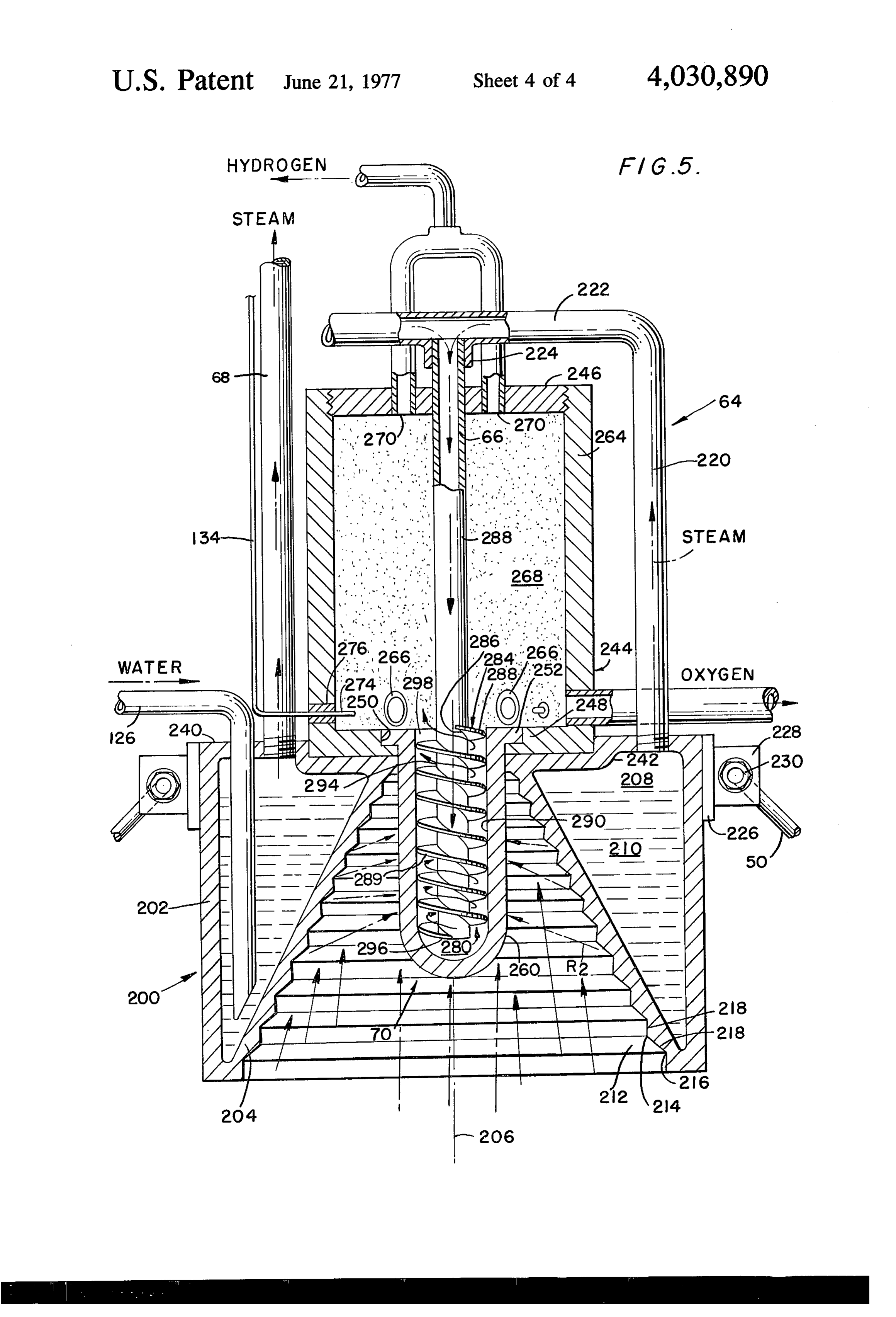
glass-like shape of water-storage tank 92 enables the nal axis 206 and conical inner wall 204 forms a frusto mirror to freely pivot about the axis through pivot conically shaped surface therearound. The inner wall points 108 and 110 without contacting the water-stor 204, together with outer wall 202 forms a chamber 208 age tank. As shown in FIG. 2, the mirror can be pivoted in which water 210 is fed via waterline 126 and is on both sides of a vertical orientation of the mirror so stored. The wall 204 forms a hollow cone about the that the mirror can track the sun as the earth turns. longitudinal centerline 206 and has an inner surface Furthermore, as shown in FIG. 3, a pump 122 is con 212 which is reflective and comprises a plurality of nected to carriage 22 and supplies water to separating ridges along the length thereof. The ridges are formed means 60 via water supply conduit 126. Water is sup by peaks 214 and valleys 216 connected by oppositely plied to pump 122 and to tank 92 via water inlet con 10 sloped surfaces 218. As will be discussed below, the duit 130. Electrical energy required to start the dissoci radiant energy reflected from mirror 42 is incident ation process is supplied to the separating means 60 upon reflective surface 212, and is reflected therefrom from a battery 132 via electrical connectors 134 and onto dissociating means 70.
discharge device 136. The thickness and material of the inner wall 204 is As shown in FIG. 4, carriage 22 rests on pivot means 15 arranged so that the radiant energy incident thereon 140 which comprises a base 142 and a frusto conically transfers sufficient heat thereto to boil water 210. shaped support 144 mounted thereon. A pivot shaft Therefore, chamber 208 forms a steam generator, and 146 having a cap 148 thereon connects the carriage 22 steam is withdrawn therefrom via steam lines 64 and to the pivot means 140. The hydrogen, oxygen and 68. As shown in FIG. 5, steam line 64 comprises a waterlines are connected to the cap 148, as is turbine 20 vertical reach 220 and a horizontal reach 222 which is water return line 150. Water can also be supplied to the connected by a boss 224 to dissociating means injector apparatus 20 via a water input line 154, which is buried tube 66. Therefore, the steam generator supplies steam in the ground and extends upwardly through the pivot to the dissociating means 70 and to the turbine 80. The means 140. The pivot means 140 is at the center of steam thus generated can be used for either driving mass of the apparatus so that movement of the appara 25 turbine 80 or for dissociating into hydrogen and oxy tus is easily effected. The solar reflecting mirror 42 is gen, or both. Efficient use of the solar energy is there best shown in FIGS. 4 and 8. fore made by apparatus 20.
As shown in FIG. 8, the reflector uppersurface 116 A supporting band 226 surrounds outer wall 202 and comprises a super reflective film 155 which is coated has lugs 228 connected thereto for connection to sup onto a ladel and then onto a glass fiber backing 156. 30 port braces 50 by locking means 230. In the preferred The mirror 42 has a circumferential flange 157 which is embodiment, the housing 200 is manufactured of stain bolted by means of bolts 157 and nuts 158 to annular less steel, or the like. The dissociating means 70 and the flanges 160 having the upper surface thereof forming inner reflective surface 212 are formed of tungsten so upper marginal edge 144 upon which struts 46 are that they will be able to withstand the temperatures mounted. In the preferred embodiment and annular 35 required to dissociate hydrogen and oxygen from water flange 160 is aluminum. The flange 154 forms a ring molecules. Furthermore, the ridges are high chromed, 162 around reflective film 150. In the preferred em bodiment, the mirror is disc-shaped and is approxi plated and to and polished to produce the maximum reflection also hold down the energy input to the stainless mately 10 meters in diameter to provide 78.54 square steel casting to prevent that casting from melting at the
high
As shown in FIG. 4, the incident energy denoted as means 60.
temperature levels achieved in the separating arrows I, is reflected from film 155 toward separating As shown in FIG. 5, the upper surface 240 of housing means 60. The reflected energy is denoted by arrows R. 200 comprises a boss 242 into which is seated a gas Pivot means 90 is best shown in FIGS. 4, 6 and 7. As chamber 244 having a removable end cap 246 thread
is shown in FIG. 4, sprocket motor 98 is mounted on ably received support post 170 and drives chain 100 to rotate bottom 248 having thereon. The gas chamber 244 has a sprocket wheel 102. As shown in FIG. 6, sprocket 102 ing flange 252 of theandissociating opening 250 therein for receiv means 70 to seat same is fixedly secured to a hub 172 which is journaled to conduit tube 174 through which the oxygen, hydrogen, therein. The dissociating means 70 is a bullet-like hol and waterlines pass. The pivot point housing 108 is 50 low chamber depending downwardly from gas chamber fixed to the conduit tube 174. A flange 176 is bolted to bottom 248 along the longitudinal axis 206 of the hous ring 48 by bolts 178 and nuts 180. As shown in FIG. 4, ing 200. The ridges in surface 212 are shaped to reflect the oxygen, hydrogen and waterlines pass conduit tube incident radiation onto the outer surface 260 of dissoci 174 to reach separator means 60 from the carriage 22. ating means 70. The radiation reflected by the ridges is The sprocket drive motor in the preferred embodiment 55 denoted as R in FIG. 5.
The gas chamber 244 comprises a vertical wall 264 is an incremental motor which is controlled by control having defined therein means 266 for withdrawing panel 118. oxygen from chamber 268, and means 270 for with Thus, in response to signals from the control panel 118, the sprocket motor is operated to move the chain 60 drawing connected hydrogen from chamber 268. Electrodes 274 to battery 132 via electrical connectors 134 100 and thus turn the sprocket wheel 102 to pivot the mirror 42 about the pivot axis through pivot housing extend through seals 276 in walls 264 of the chamber 108 and 110. As shown in FIG. 7, housing 108 is com 244. Surrounding injector tube 66 and located within chamber 280 of the dissociating means 70 is a spiral prised of a pair of keeper means 180 and 182 bolted flange 284 which has an inner surface 286, contacting together by bolts 184 and nuts 186.
The separator means is best shown in FIGS. 1 and 5. edge 289 which288 65 outer surface of the injector tube 66 and outer contacts inner surface 290 of the disso
As shown in FIG. 5, the separator means comprises a housing 200 having an outer wall 202 and a conically ciating means chamber 280. The helical flange 284 shaped inner wall 204. The housing 200 has a longitudi therefore forms a spiral path 294 through which steam
Page 9
from outlet means 296 of injector tube 66 must pass in cules. Instead, solar energy is utilized to supply the heat order to exit the chamber 280 via outlet means 298. required to raise the steam in dissociating chamber 280 Appropriate check valves, or other such elements to levels sufficient to dissociate the hydrogen and oxy (not shown), can be placed in the steam, hydrogen and gen therefrom. Pump 122 can also be driven by battery oxygen lines to maintain the pressure in the separating 132 at various times to boost the pressure in chamber and dissociating means at suitable levels. 208 when desired. Furthermore, check valves (not While traversing the spiral path 294, the steam must shown) can be inserted into the various conduits, such contact the inner surface 290 of the dissociating means. as steamline 68 or steamline 64, to control the flow The dissociating means is formed of a material having a therethrough and to shunt more steam to one or the thickness and a thermal conductivity selected to trans other of the turbines or dissociating means. fer sufficient heat from the radiation incident upon As shown in FIG. 1, the turbine generator assembly outer surface 260 to the steam which heat is sufficient receives steam from the separating means 60, and as to raise the temperature of the steam in chamber 280 to shown in FIG. 4, steam from the turbine 80 can be the dissociation temperature of that steam. Therefore, re-injected into the system via turbine water return line while traversing the spiral path 294, the steam is trans 15 150. The hot steam in line 150 serves to preheat the formed into hydrogen and oxygen gases which are then water being forced into chamber 208 to efficiently use forced out of outlet 298 into chamber 268. the energy generated in this apparatus. The generator While traversing the spiral path, the gases undergo 80 can be used to drive other electrically powered circular movement and therefore subject the compo devices and/or recharge battery 132, or to power con nents thereof to centrifugal forces. As oxygen is heavier trol panel 118.
than hydrogen, oxygen moves radially outward while The oxygen and hydrogen conduit can be routed displacing the hydrogen radially inward toward center around the apparatus and then extend outwardly to line 206. As shown in FIG. 5, the oxygen outlet means compressor or other such devices. In this manner, the 266 are located in the vertical walls 264 at the bottom heat given off by these lines can be utilized to preheat of chamber 268, while hydrogen withdrawing means 25 the water being injected into chamber 208 to thereby 270 are located near injector tube 66 at the top of the make sufficient use of the heat generated by the appa chamber. Therefore, the oxygen, being heavier then ratus 20.
the hydrogen, has moved radially outward from center In operation, start-up of the apparatus is effected line 206 and will be located closer to the bottom of the using the discharge devices 136. Solar energy incident chamber 260 than the hydrogen. The appropriate with on mirror 42 is reflected thereby onto inner surface drawal means are therefore located at a position to 212 to heat water inducted into chamber 208 via water receive the hydrogen and the oxygen separated by line 126 and to be reflected onto surface 260 of the separating means 60. dissociating means 70 to heat steam inducted into As shown in FIG. 1, the hydrogen withdrawal means chamber 280 thereof. Steam is inducted into chamber comprises four conduits connected together to form a 35 280 via steam lines 64 and injector 66. The steam in branched header 300 for hydrogen conduits 76, and chamber 280 is forced to transverse a spiral path by a ring manifold 302 is connected by radial conduits 304 helical flange and is thereby forced to undergo rota to form a header for oxygen conduit 98. Ring manifolds tional movement which compacts the inner surface of 305 and 306 form hydrogen headers. It is noted that the chamber 280. Solar energy reflected from mirror there are two headers for hydrogen for each oxygen 40 42 and from surface 212 is incident upon the outer header as there is twice as much hydrogen produced as surface 260 and the heat generated thereby is trans oxygen in this dissociation reaction. If a steam header is ferred to the inner surface 290 of the chamber 280 to used, it also can be a ring-type header surrounding the heat the steam therein to the dissociation temperature separating means, as do manifolds 302-306, with ap of water. The hydrogen and oxygen dissociated in propriate radial conduits, or the like, connecting that 45 chamber 280 undergo rotational movement to force manifold to the separating means so that steam from the heavier oxygen toward the outside of the chamber chamber 208 can be conducted thereinto through and the lighter hydrogen toward the inside of the cham valves, or the like, which are controlled either manu ber. Withdrawing means are located in gas chamber fally or remotely, such as by controls on panel 118 to 244 at positions to receive the hydrogen and oxygen shunt steam thereinto when needed. and withdraw same from the chamber 268. The hydro An auxiliary start-up system comprises the electrodes gen and oxygen are then moved to appropriate loca 274 and the battery 132. Water is injected into cham tions. The steam not used in the dissociation process ber 208 by pump 122 via conduit 126, and solar energy can be used to drive a turbine generator set via a steam boils this water to form steam. Some of the steam is line 68.
conducted to the turbine generator assembly, and some 55 A control program controls the movement of the of the steam is injected into the dissociating means. The device in a manner such that, during the daylight hours, electrodes 274 are fired to produce sufficient energy to the mirror is oriented at a location which makes maxi dissociate the steam in the dissociating means while the mun use of the Solar energy incident thereon. The rest of the water in chamber 208 is being heated. As control program moves the mirror as the angle of the soon as the water in chamber 208 is heated to predeter 60 Sun is changed by rotation of the earth. The mirror is mined levels, the temperatures in chamber 280 will then reset during the night hours to recapture incident have reached levels sufficient to dissociate the steam radiation at Sunrise. The start-up procedure is then injected therein, and the auxiliary dissociating means initiated, then shut down when the solar energy is suffi comprising electrodes 274 is no longer required. cient to make the apparatus self perpetuating, and the Therefore, once started, the apparatus embodying the 65 process continued. The energy generated by the tur present invention is self perpetuating and does not rely bine generator set is used in any suitable manner, and on hydrocarbon fuels to supply the energy required to the hydrogen and oxygen generated by the apparatus dissociating hydrogen and oxygen from water mole 20 is also used in any suitable manner.
Page 10
As this invention may be embodied in several forms to start said electrical energy discharge at predeter without departing from the spirit or essential character mined times and to stop same when heat energy in istics thereof, the present embodiment is therefore sufficient amounts to separate oxygen and hydrogen illustrative and not restrictive, since the scope of the from each other is transferred to said steam by said invention is defined by the appended claims rather than second source of heat energy.
by the description preceding them, and all changes that 5. The apparatus of claim 2 further including a mov fall within the metes and bounds of the claims or that able carriage supporting said solar energy reflecting form their functional as well as conjointly cooperative means and wherein said housing is connected to said equivalents, are therefore intended to be embraced by solar energy reflecting means. : those claims. 10 6. The apparatus of claim 5 further including means What is claimed is: for moving said carriage. .' . 1. Apparatus for separating hydrogen and oxygen 7. The apparatus of claim 6 further including a tur from water comprising: bine-generator set mounted on said carriage and con a housing exposed to incident solar energy and hav nected to said chamber to receive steam therefrom to ing defined therein a chamber for storing water; 15 drive said turbine.
means for conducting water into said chamber; 8. The apparatus of claim 1, wherein said arcuate a solar energy reflecting means for reflecting solar path is spiral.
energy toward said housing; 9. An apparatus for separting hydrogen and oxygen first heat transfer means located on said housing to from water, comprising:
receive said incident solar energy and be heated 20 a solar reflector having a central axis; thereby to form a first source of heat energy, said mounting means for mounting said solar reflector first heat transfer means being connected to said including moving means for moving said solar re chamber in a manner such that said heat energy flector in two planes, including rotating means on from said first source is transferred to water in said said mounting means for rotating said solar reflec chamber in amounts sufficient to boil same to pro 25 tor in one plane, and moving means mounted on duce steam; said mounting means for moving said solar reflec solar energy reflecting means connected to said first tor in a second plane so that said solar reflector will heat transfer means for reflecting part of said inci reflect solar energy;
dent solar energy to form reflected solar energy;
separating means connected to said housing and con 30 oxygen frommeans dissociating for dissociating hydrogen and water, said dissociating means being nected to said chamber to receive steam therefrom, mounted on said solar reflector in a location to said separating means having second heat transfer receive solar energy reflected thereby, and includ means positioned thereon to receive said incident ing a solar energy reflecting means positioned to and said reflected solar energy and be heated receive solar energy reflected by said solar reflec thereby to form a second source of heat energy, 35 tor and reflecting part of that solar energy onto said said second heat transfer means being connected to dissociating means, evaporating means for concen said separating means and transferring heat from trating said reflected solar energy onto water lo said second source of heat energy to said steam in cated therein to boil said water to form steam, and amounts sufficient to separate said steam into hy dissociating means for concentrating solar energy
said separating means including a case connected to onto said steam until the temperature of said steam said housing having means therein for defining an corresponds to the dissociation temperature of said arcuate path over which said hydrogen and oxygen steam thereby dissociating hydrogen and oxygen components pass for creating rotational movement from said steam;
of said hydrogen and oxygen components to sepa 45 means for conducting water into said evaporating rate same by centrifugal forces generated thereon means;
by said rotational movement and means on said evaporating means for conducting removal means on said housing for removing said steam into said dissociating means; separated hydrogen and oxygen components from means for separating said hydrogen and oxygen from said separating means. 50 each other which includes means for defining a 2. The apparatus of claim 1 wherein said solar energy spiral path over which said hydrogen and oxygen refecting means includes a movable solar reflector flow in a manner which creates centrifugal forces mirror and moving means connected to said solar re to separate said components from each other; and flector mirror for moving said solar reflector mirror so means connected to said dissociating means for with that it will be exposed to radiant energy during substan 55 drawing said hydrogen and oxygen therefrom. tially all daylight hours. 10. A device for separating hydrogen and oxygen 3. The apparatus of claim 1 wherein said removal from water comprising:
a housing;
means includes hydrogen removing means located on said housing to receive said hydrogen and oxygen re evaporator means on said housing for boiling water moving means located on said housing to receive said 60 contained therein to form steam;
oxygen. means connected to said housing for transferring 4. The apparatus of claim 3 further including start-up water into said evaporator means; means having an electrical energy discharge means first solar concentrating means for concentrating located on said separating means to discharge energy solar energy onto said evaporator means to heat into said steam in amounts sufficient to separate hydro 65 said water to evaporate same; gen and oxygen from each other, an electrical energy separator means on said housing for dissociating said source connected to said discharge means, and means steam to form hydrogen and oxygen said separator for controlling said start-up means for actuating same means having reflecting means thereon for reflect
Page 11
ing solar energy focused thereon by said first solar to have rotational motions so that centrifugal concentrating means; forces generated thereby separate said components second solar concentrating means for concentrating from each other;
solar energy onto said separator means to raise the hydrogen transfer means on said separator means for temperature of said steam to dissociate same; withdrawing said hydrogen from said separator steam transfer means on said evaporator for transfer means; and ring steam from said evaporator means to said oxygen transfer means on said separator means for separator means;
a means on said separator means defining a spiral withdrawing said oxygen from said separator path over which said hydrogen and oxygen pass, O eaS.
said spiral path causing said hydrogen and oxygen
Provenance
- Collection
- Cited prior art
- Original PDF
- patentimages.storage.googleapis.com →
- Filed
- 1975-10-20
- Pages
- 11
- Method
- pdftotext (the PDF's own text layer) + pdftoppm 300dpi page scans
- Source
- Google Patents bibliographic record
- Granted
- 1977-06-21
- Inventors
- Richard E. Diggs
- Transcribed from
- patentimages.storage.googleapis.com →