patent · US3157172
Ozonizing means in combustion engines
17 November 1964
Page 1
Drawing sheet — no readable text.
Page 2
Drawing sheet — no readable text.
Page 3
United States Patent Office 3,157,172 Patiented Nov. 17, 1964
3,57,172 instead of the battery system, the well known magneto OZONZNG RAEANS EN COM 3USEON ENGINSES System may be used, in which the voltage required to Georg S. Miteistaedt, 274 73rd St. Brookiya, N.Y. cause flow of current in the primary winding of the Fied May 26, 1963, Ser'. No. 280,935 ignition coil is generated by the rotation of a set of 15 CEains. (C. 123-19) permanent magnets, instead of being Supplied by a battery.
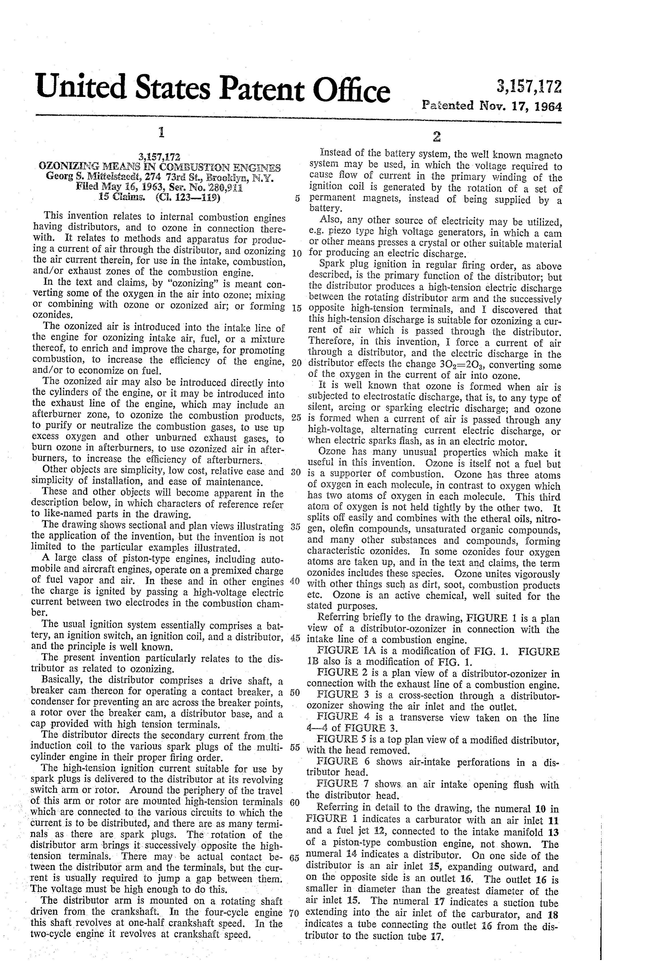
This invention relates to internal combustion engines Also, any other source of electricity may be utilized, having distributors, and to ozone in connection there e.g. piezo type high voltage generators, in which a cam with. It relates to methods and apparatus for produc or other means presses a crystal or other suitable material ing a current of air through the distributor, and ozonizing 0. for producing an electric discharge. the air current therein, for use in the intake, combustion, Spark plug ignition in regular firing order, as above and/or exhaust zones of the combustion engine. described, is the primary function of the distributor; but In the text and claims, by "ozonizing” is meant con verting some of the oxygen in the air into ozone; mixing the distributor produces a high-tension electric discharge between the rotating distributor arm and the Successively or combining with ozone or ozonized air; or forming 15 opposite high-tension terminals, and discovered that ozonides. this high-tension discharge is suitable for ozonizing a cur The ozonized air is introduced into the intake line of rent of air which is passed through the distributor. the engine for ozonizing intake air, fuel, or a mixture Therefore, in this invention, I force a current of air thereof, to enrich and improve the charge, for promoting through a distributor, and the electric discharge in the combustion, to increase the efficiency of the engine, distributor effects the change 3O2=2O3, converting some and/or to economize on fuel. of the oxygen in the current of air into ozone. The ozonized air may also be introduced directly into It is well known that ozone is formed when air is the cylinders of the engine, or it may be introduced into subjected to electrostatic discharge, that is, to any type of the exhaust line of the engine, which may include an silent, arcing or sparking electric discharge; and ozone afterburner zone, to ozonize the combustion products, 25 is formed when a current of air is passed through any to purify or neutralize the combustion gases, to use up high-voltage, alternating current electric discharge, or excess oxygen and other unburned exhaust gases, to when electric sparks flash, as in an electric motor. burn ozone in afterburners, to use ozonized air in after Ozone has many unusual properties which make it burners, to increase the efficiency of afterburners. useful in this invention. Czone is itself not a fuel but Other objects are simplicity, low cost, relative ease and is a supporter of combustion. Ozone has three atoms simplicity of installation, and ease of maintenance. of oxygen in each molecule, in contrast to oxygen which These and other objects will become apparent in the has two atoms of oxygen in each molecule. This third description below, in which characters of reference refer aton of oxygen is not held tightly by the other two. It to like-named parts in the drawing.
The drawing shows sectional and plan views illustrating 3 5 splits gen, off easily and combines with the etheral oils, nitro olefin compounds, unsaturated organic compounds, the application of the invention, but the invention is not and many other substances and compounds, forming limited to the particular examples illustrated. characteristic ozonides. In some ozonides four oxygen A large class of piston-type engines, including auto atoms are taken up, and in the text and claims, the term mobile and aircraft engines, operate on a premixed charge of fuel vapor and air. In these and in other engines with otherincludes
ozonides things these species. OZone unites vigorously such as dirt, soot, combustion products the charge is ignited by passing a high-voltage electric etc. Ozone is an active chemical, well Suited for the current between two electrodes in the combustion cham stated purposes.
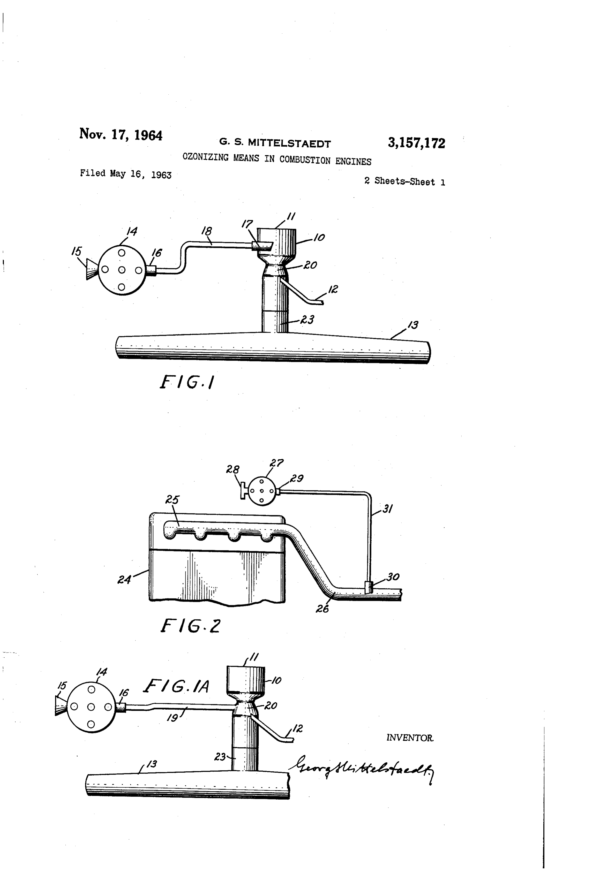
ber. Referring briefly to the drawing, FIGURE 1 is a plan The usual ignition system essentially comprises a bat view of a distributor-ozonizer in connection with the tery, an ignition switch, an ignition coil, and a distributor, 45 intake line of a combustion engine. and the principle is well known. FIGURE 1A is a modification of FiG. 1. FIGURE The present invention particularly relates to the dis 1B also is a modification of FIG. 1. tributor as related to ozonizing. FIGURE 2 is a plan view of a distributor-ozonizer in Basically, the distributor comprises a drive shaft, a connection breaker cam thereon for operating a contact breaker, a 50 FIGUREwith 3 the exhaust line of a combustion engine.
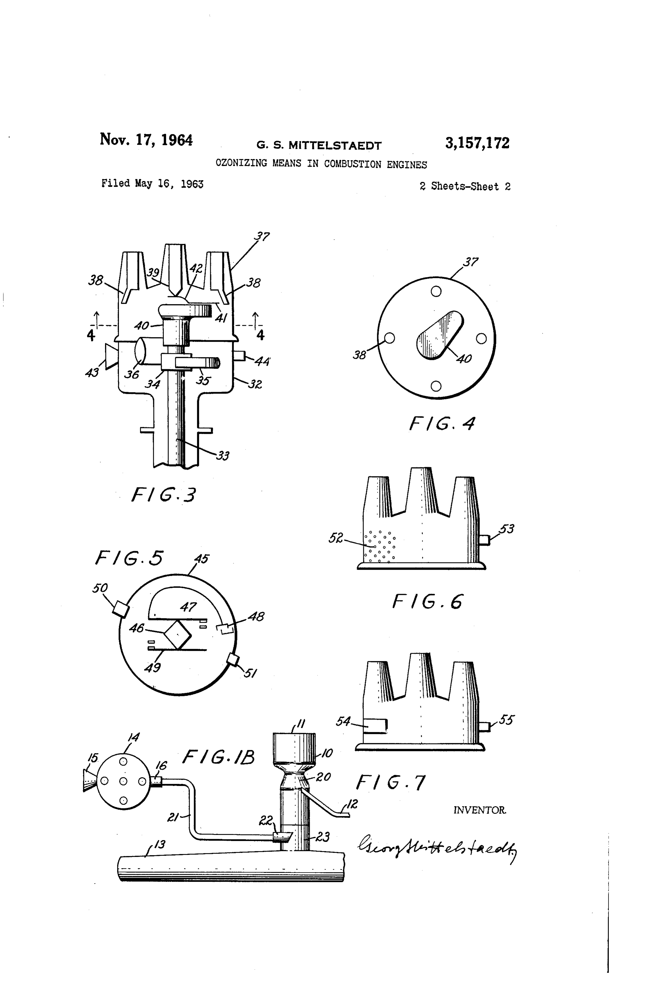
is a cross-section through a distributor condenser for preventing an arc across the breaker points, ozonizer showing the air inlet and the outlet. a rotor over the breaker cam, a distributor base, and a FIGURE 4 is a transverse view taken on the line cap provided with high tension terminals. A-4 of FIGURE 3.
The distributor directs the secondary current from the FIGURE 5 is a top plan view of a modified distributor, induction coil to the various spark plugs of the multi 55 with the head removed.
cylinder engine in their proper firing order.
The high-tension ignition current suitable for use by tributor head.6 shows air-intake perforations in a dis
FIGURE
spark plugs is delivered to the distributor at its revolving FEGURE 7 shows an air intake opening flush with switch arm or rotor. Around the periphery of the travel the distributor head.
of this arm or rotor are mounted high-tension terminals 60 Referring in detail to the drawing, the numeral 10 in which are connected to the various circuits to which the FIGURE 1 indicates a carburator with an air inlet 11 current is to be distributed, and there are as many termi nals as there are spark plugs. The rotation of the and a fuel jet 12, connected to the intake manifold 13 distributor arm brings it successively opposite the high of a piston-type combustion engine, not shown. The tension terminals. There may be actual contact be numeral 4 indicates a distributor. On one side of the tween the distributor arm and the terminals, but the cur distributor is an air inlet 25, expanding outward, and rent is usually required to jump a gap between them. on the opposite side is an outlet 16. The outlet 16 is The voltage must be high enough to do this. - smaller in diameter than the greatest diameter of the The distributor arm is mounted on a rotating shaft air inlet 15. The numeral 7 indicates a suction tube driven from the crankshaft. In the four-cycle engine 70 extending into the air inlet of the carburator, and 18 this shaft revolves at one-half crankshaft speed. In the indicates a tube connecting the outlet 16 from the dis two-cycle engine it revolves at crankshaft speed. tributor to the suction tube 17.
Page 4
In this arrangement the intake of the pistons within tube downstream of the combustion zone, then the ozon the cylinders of the engine will cause a draft through the ized air will primarily purify and/or neutralize the ex intake line and carburator, and the suction tube 17 and haust gases.
tube 18 will draw air through the distributor, in which Of course, as stated above, any type pump or any other the air stream will be acted upon by the electric discharge 5 means may be utilized to force a current of air through and will be ozonized. the distributor, and to force the ozonized air from the The ozonized air is drawn through the tubes 17 and 18 distributor into the exhaust line of the combustion engine. out of the distributor and into the carburator, and from FIGURE 3 is a longitudinal cross-section of a distribu there into the cylinders. In the carburator, the ozonized tor, showing an application of the invention. Here the air will enrich the air-fuel mixture and will produce a O numeral 32 indicates the distributor base, and 33 indicates highly combustible vapor, which will increase the effi the drive shaft. The numeral 34 indicates the breaker ciency of the engine. cam for operating contact breaker 35, and 36 shows a In FIGURE A, the line 19 indicates a tube leading condenser for preventing an arc across the breaker points, from the distributor outlet 16 to the venturi 20 of the not shown. The distributor cap 37 has a series of high carburator, and opening into the venturi immediately tension terminals 38 placed in a circle around a central downstream of its throat, for drawing ozonized air into high-tension terminal 39. A rotor 40 is mounted on the the carburator. In FIGURE 1B, the line 21 indicates breaker cam 34 under the cap and rotates with the cam. a tube leading from the distributor outlet 16 to the suc As it rotates, a metal segment 41 in the rotor sweeps past tion tube 22 extending into the intake zone 23 of the the outer high-tension terminals 38. The metal segment manifold 13, for ozonizing the air and fuel mixture. 20 41 is connected by a spring 42 to the center high-tension The line from the outlet 16 of the distributor may be terminal 39. Therefore, the rotor 40 connects the center connected to any part of the intake line, also without en terminal 39 to the outer terminals 38, one after the other, tering, and may be connected to several parts thereof. as it turns, and the rotor is successively opposite the outer For instance, the line may use the low pressure in the high-tension terminals for effecting a high voltage dis carburator venturi and the intake manifold to produce charge. The numeral 43 indicates a conical air inlet in the proper suction. the distributor base, and 44 indicates an outlet from the The line from the distributor outlet 16 preferably con base which will be connected to the intake and/or ex nects to the intake line of the engine upstream of the haust lines of the combustion engine. throttle valve, e.g. as illustrated at 8-7 in FIGURE 1, In operation, an air current is passed through the dis thereby preventing too lean a mixture during light load 30 tributor and is ozonized therein by the high voltage elec and idling operations. tric discharge, for use in the combustion engine. It can The invention essentially comprises forcing air through also be seen that the rotor 40 will act to mix and com a distributor and ozonizing the air stream in the distribu press the air passing through the distributor, thereby tor, for use in the combustion engine, and any means to providing more uniform ozonizing, and tending to increase this end may be utilized. the yield of ozone.
It must be understood that any pump or means may be FIGURE 4 is a transverse view taken on line 4-4 of utilized to force a current of air through a distributor, FIGURE 3. Again, the numeral 37 indicates the distrib and force the ozonized air from the distributor into the utor cap, 38 shows the outer high-tension terminals, and intake Zone, the combustion zone, or the exhaust Zone of 46 indicates the rotor. As it rotates, high-tension ozon the combustion engine. 40 izing discharges are effected between the metal segment In the text and claims, by "intake line' is meant any at the end of the rotor arm and successive outer high part thereof between air intake and cylinders; by “ex tension terminals.
haust line' is meant any part thereof between the cylin FIGURE 5 is a top plan view of a distributor with the ders and the end of the exhaust line. cap removed, illustrating a modification of the device. In FIGURE 2, the numeral 24 indicates a piston type 45 Here the numeral 45 indicates the distributor base, 46 combustion engine, having an exhaust manifold 25 and the breaker cam, 47 the contact breaker, and 48 the con an exhaust tube 26. The numeral 27 indicates a distribu denser, as is usual. But in this modification there is an tor. On one side of the distributor is an air inlet 28, extra contact breaker 49 operated by the same breaker expanded at the outer end, and on the opposite side of cam 46. This contact breaker 49 is connected to the the distributor is an outlet 29. The outlet 29 is smaller 50 battery and is designed to produce an arc across its break in diameter than the greatest diameter of the air inlet er points, for further increasing the ozonizing effect. The 28. It is to be noted that in this invention the distribu numeral 50 indicates an air inlet in the distributor base and tor inlet and outlet do not have to be opposite, but may 5i shows the outlet, the air inlet being greater in diam be placed in any suitable position. The numeral 3 (9 indi eter than the outlet. . cates a suction tube extending into the exhaust tube 26, FIGURE 6 shows a distributor cap in which the air and 31 indicates a tube connecting the outlet 29 of the inlet consists of perforations 52. All or part of the cap distributor to the suction tube 30. may be perforated. The numeral 53 indicates the outlet. The suction tube 39 produces a low pressure area which FIGURE 7 shows a distributor cap in which the air will cause a draft of air, through the distributor 27, in inlet is an opening 54 which is substantially flush with the which the air stream will be acted upon by the electric 60 Cap.
discharge, and will be ozonized. Air inlets as shown in FIGURES 6 and 7 may also be The ozonized air is drawn through the tubes 30 and 32 of the distributor and into the exhaust tube, where it they mayinbethe disposed distributor base, in both base and cap, or arranged partly in the base and partly in the will ozonize the exhaust. The suction tube 30 may be cap, or therebetween. s disposed in any part of the exhaust line; or any other 65 The described air current through the distributor also means may be provided in the exhaust line, perhaps a acts as cooling means for the distributor, and this is part Venturi, for producing a low pressure area, to draw ozon of the present invention.
ized air from the distributor outlet into the exhaust line.
The line 31 from the distributor outlet 29 may be con It is to be understood that fuel injection or any other nected to any part of the exhaust line, and may be con 70 fuel System may be used in connection with the described nected to several parts thereof to produce the proper re distributor-Ozonizer, and this forms part of this invention. . Sults. If the line 31 is connected to the afterburner zone, andIt described is to be noted that the devices and features illustrated are interchangeable.
the ozonized air will aid combustion and tend to increase thrust, which is important in connection with airplanes. The drawings and description are illustrative and ex If the line 31 is connected to a portion of the exhaust planatory only, and the invention is not limited thereto,
Page 5
and various changes may be made without departing form discharge between its breaker points and increasing the the spirit or scope of the invention. yield of ozone in the distributor. In the text and claims, by "tube' is also meant duct, 6. In a multicylinder combustion engine having a channel, passage, line; by "suction tube' is meant any combustion line, an ignition system including a distrib tube which produces suction, and/or which conveys suc utor directing the ignition current to the various spark tion flow, also in part; by "suction line' is meant a tube plugs of the engine in their proper firing order, an inlet leading to a suction tube or other low pressure area, or and an outlet in the distributor, and a tube leading from which produces suction; by "combustion line” is meant said outlet to the combustion line of the engine, the im intake, combustion and exhaust zones of the engine; by provement consisting in that the tube from the distributor "inlet' is meant tube, duct, opening, slits, perforations, IO outlet extends into and within the combustion line, thereby pores, or any other means of ingress; by “outlet' is meant producing a low pressure area at the aspiration point. tube, duct, opening, vent, or any other means of egreSS. 7. In a multicylinder combustion engine having a The principles involved in this invention may be ap combustion line, an ignition system including a distributor plied to all fields of combustion as related to the type directing the ignition current to the various spark plugs of ozonator described. 5 of the engine in their proper firing order, an inlet and I claim: an outlet in the distributor, and means restricting the con 1. In a multicylinder combustion engine having an in bustion line thereby producing a low pressure area there take line, a combustion zone, an exhaust line, and an ignition system including a distributor which comprises in, a tube leading from the distributor outlet to the re stricted low pressure area.
a base, a driveshaft, a breaker cam on the driveshaft op 20 8. In a multicylinder combustion engine having an in erating a primary-circuit breaker, a condenser, a rotor take line, a combustion zone, an exhaust line, an ignition mounted on the driveshaft over the breaker cam, a cap system including a distributor directing the ignition cur disposed on the distributor base, a series of high-tension rent to the various spark plugs of the engine in their terminals in the cap placed in a circle around a central proper firing order, an inlet into the distributor, and an high-tension terminal, a metal segment in the rotor arm 25 outlet from the distributor connected with the intake Sweeping past the outer high-tension terminals, and means line of the engine, the improvement consisting in that connecting said segment to the center high-tension ter said inlet into the distributor is subjected to pressure great minal, an air inlet and an outlet in the distributor, a con er than the static pressure in the intake line of the en necting tube leading from said outlet to the exhaust gine.
line of the engine, and means producing flow through 9. In a multicylinder combustion engine having a said inlet into the distributor, through said outlet out of combustion line, an ignition system including a distributor the distributor, and through the connecting tube into directing the ignition current to the various spark plugs the exhaust line of the combustion engine. of the engine in their proper firing order, an inlet into 2. In a multicylinder combustion engine having an in the distributor, an outlet from the distributor, a tube lead take line, a combustion zone, an exhaust line, an ignition ing from said outlet to the combustion line of the en system including a distributor directing the ignition cur gine, and means producing flow through said inlet into the rent to the various spark plugs of the engine in their distributor, through said outlet out of the distributor, and proper firing order, an inlet into the distributor, and an through said tube into the combustion line of the en outlet from the distributor, means connecting said outlet gine, the improvement consisting in that said inlet into to the exhaust line of the engine. 40 the distributor is subjected to at least atmospheric pres 3. In a multicylinder combustion engine comprising a sure; said flow being ozonized by the electrical discharge combustion line, an ignition system including a distribu in the distributor, for use in the combustion line. tor with a breaker cam and a contact breaker and direct 10. In a multicylinder combustion engine having a ing the ignition current to the various spark plugs of combustion line, an ignition system including a distrib the engine in their proper firing order, an inlet and an 45 utor directing the ignition current to the various spark outlet in the distributor, and means connecting said out plugs of the engine in their proper firing order, an inlet let to the combustion line, an extra contact breaker in in the distributor, and an outlet from the distributor con dependent of spark plug ignition disposed in the distribu nected to the combustion line of the engine, an inlet en tor and operated by said same breaker cam, for produc largement on the distributor subjected to atmospheric ing additional ozone in the distributor for use in the 50 pressure.
combustion line of the engine. 11. In a multicylinder combustion engine comprising 4. In a multicylinder combustion engine comprising a an intake line including a throttle valve, a combustion combustion line, an ignition system including a distribu Zone, an exhaust line, an ignition system including a dis tor directing the ignition current to the various spark tributor directing the ignition current to the various spark plugs of the engine in their proper firing order, an inlet 55 plugs of the engine in their proper firing order and an and an outlet in the distributor, and means connecting inlet into the distributor subjected to pressure greater said outlet to the combustion line, electric discharge than the static pressure in the intake line of the engine, means independent of spark plug ignition disposed in the an outlet from the distributor connected with the intake distributor for producing additional ozone for use in the line of the engine upstream of the throttle valve. combustion line of the engine. 60 12. In a multicylinder combustion engine comprising 5. In a multicylinder combustion engine comprising an an intake line including a carburator equipped with intake line, a combustion Zone, an exhaust line, an igni valves, a combustion zone, an exhaust line, an ignition tion system including a distributor having a breaker cam System including a distributor directing the ignition cur and a contact breaker and directing the ignition current rent to the various spark plugs of the engine in their proper firing order, and an inlet into the distributor sub to the various spark plugs of the engine in their proper 65 jected firing order, an inlet and an outlet in the distributor, a to atmospheric pressure, an outlet from the distrib tube leading from said outlet to the intake line of the utor connected with the intake line of the engine at a engine, and means producing flow through said inlet into point 13.
upstream of the carburator valves.
In a multicylinder combustion engine comprising the distributor, through said outlet out of the distributor, 70 an intake line including a throttle valve, a combustion and through said tube into the intake line of the engine, Zone, an exhaust line, an ignition system including a dis the flow being ozonized by the high-tension discharge in the distributor, an extra contact breaker independent tributor directing the ignition current to the various spark plugs of the engine in their proper firing order, an inlet of spark plug ignition mounted in the distributor and op into erated by said same breaker cam, producing an electrical 75 sure the distributor subjected to at least atmospheric pres and an outlet from the distributor, the improvement
Page 6
consisting in that said outlet is connected to the intake tion current to the various spark plugs of the engine in line of the engine outwardly of the throttle valve. their proper firing order, an inlet and an outlet in the 14. In a multicylinder combustion engine comprising distributor, a connecting tube leading from said outlet an intake line, a combustion zone, an exhaust line, an to the exhaust line of the engine, and means producing ignition system including a distributor having a breaker flow through said inlet into the distributor, through said cam and a contact breaker and directing the ignition cur outlet out of the distributor, and through said connecting rent to the various spark plugs of the engine in their tube into the exhaust line of the combustion engine. proper firing order, an inlet and an outlet in the distrib References Cited by the Examiner utor, a tube leading from said outlet to the exhaust line of the engine, and means producing a flow through said O UNITED STATES PATENTS inlet into the distributor, through said outlet out of the 1,778,036 10/30 Noble ---------------. 123-119 distributor, and through said tube into the exhaust line 1,813,808 7/31 Kuehn.
of the engine, the flow being ozonized by the high-tension 1,982,484 1 1/34 Runge --------------- 123-119 discharge in the distributor, an extra contact breaker 2,149,516 3/39 Flamm -------------- 123-198
independent of spark plug ignition mounted in the distrib utor and operated by said same breaker cam, producing 2,251,387 8/41 Arthur ---------------- 200-19 an electrical discharge between its breaker points and in 2,634,341 4/53 Rosen ----------------- 200-19 creasing the yield of ozone in the distributor. 2,798,471 7/57 Kiekhaefer ---------- 123-41.31 15. In a multicylinder combustion engine having an intake line, a combustion zone, an exhaust line and an 20 RICHARD B. WILKINSON, Primary Examiner. ignition system including a distributor directing the igni KARL J. ALBRECHT, Examiner.
Provenance
- Collection
- Cited prior art
- Original PDF
- patentimages.storage.googleapis.com →
- Filed
- 1963-05-16
- Pages
- 6
- Method
- pdftotext (the PDF's own text layer) + pdftoppm 300dpi page scans
- Source
- Google Patents bibliographic record
- Granted
- 1964-11-17
- Inventors
- Georg S Mittelstaedt
- Transcribed from
- patentimages.storage.googleapis.com →