patent · US5733421
Hydrogen-oxygen fuel cell
31 March 1998
Page 1 — bibliographic record
III
United States Patent (19) 11 Patent Number: 5,733,421 Pettigrew et al. 45 Date of Patent: Mar. 31, 1998 54 HYDROGEN-OXYGEN FUEL CELL Casper, Hydrogen Manufacture by Electrolysis, Thermal Decomposition and Unusual Techniques, Noyes Data Copr 76) Inventors: J. W. Pettigrew; Gregory R. Monette;
David H. Hirsch, all of 3705 Arctic (1978) pp. 111-207 (month N/A).
(21) Appl. No.:715,583 Primary Examiner-Donald R. Valentine Attorney, Agent, or Firm-Michael J. Tavella
(51) Int. Cl. ............................... C25B 9/00; C25B 15/08 57 ABSTRACT (52) U.S. Cl. .......................... 204/228; 204/229; 204/270;
204/268 A hydrogen-oxygen fuel cell that uses an electrolysis unit 58) Field of Search ..................................... 204/228, 270, that is sealed and has protection from explosions and cor 204/229, 230, 268 rosion. It has a plate structure that produces maximum (56) References Cited efficiency of hydrogen production and can adjust the output
automatic fill system to keep the electrolyte solution at the 3.957,618 5/1976 Spirig ...................................... 204/270 proper levels for efficient hydrogen production, and the 4,014,777 3/1977 Brown ..... ... 204/270 4,379,043 4/1983 Chappelle ... 204/229 temperature of the electrolysis chamber remains low, 4,457,816 7/1984 Galluzzo et ad. 204/27OX thereby reducing the problems of cooling the chamber and 4.726,888 2/1988 McCambridge ... ... 204/270 X 5,082.544 1/1992 Willey et al. ........................... 204270 the risk of melting the chamber. The device has an extraction 5231954 8/1993 Stowe. chamber that is baffled to prevent backwash of electrolyte 5,628,885 5/1997 Lin ..................................... 204/27OX solution out of the electrolyte chamber. The device has an
OTHER PUBLICATIONS explosion preventer that reduces the explosion risk by Dahiya, Progress in Hydrogen Energy, D. Reidel Publishing working the produced gasses through a neutral fluid.
Graham & Trotman. Hydrogen Energy Vector of the Future, 24 Claims, 6 Drawing Sheets
Page 2
Drawing sheet — no readable text.
Page 3
Drawing sheet — no readable text.
Page 4
Drawing sheet — no readable text.
Page 5
Drawing sheet — no readable text.
Page 6
Drawing sheet — no readable text.
Page 7
Drawing sheet — no readable text.
Page 8
HYDROGEN-OXYGEN FUEL CELL some smaller engines may receive an excess amount of hydrogen while some larger engines may not receive
This invention relates to hydrogen-oxygen fuel cells and enough. Second, the use of two plates does not produce the particularly to hydrogen-oxygen fuel cells in a closed cham optimum efficiency of hydrogen production. The process ber for use in vehicles, takes some time to begin. And because of the spacing between the plates, the reaction can generate a considerable
BACKGROUND OF THE INVENTION amount of heat. As the level of electrolyte drops within the There are two major problems in the operation of fossil chamber, the temperature increases, gas production fueled vehicles that have existed for some time. The first is decreases and steaming may occur. Because there is no the apparently limited supply of fossil fuels. The second is monitoring device or automatic level control, the interior of the pollution that these vehicles produce. Even if the supply the unit must be inspected regularly to ensure proper levels of fossil fuels expands, it is still good policy to conserve as of electrolyte are maintained. Opening the vessel to inspect much as practical. One of the key concerns of conservation it creates the possibility of contamination of the electrolyte. is the cost of the particular measure. So, the ideal conser 15 Moreover, opening the vessel exposes the user to hydrogen vation measure is one that produces significant reductions in gas, which is dangerous. Third, if these levels are not fuel use at the lowest possible cost. maintained, the heat generated may be sufficient to melt or damage the plastic containment cylinder. Fourth, placing the
The second problem centers on the emissions produced electrodes when burning fossil fuels. Vehicles burning such fuels often the electrolyte at the side of the container can produce leaks as produce carbon monoxide, nitrous oxides, sulfur dioxide and accumulation zone corrodes the connections. Finally, the gas other noxious gasses. These products are a result, in part, of large. It is possibleattothe top of the cylindrical chamber is accumulate significant quantities of engines not completely burning the fuel.
It has long been known that hydrogen is a near perfect explode. The pop off top does little toand explosive hydrogen within this zone then have this gas prevent the explosion fuel. It releases almost three times the energy of fossil fuels and may act as a missile once an explosion occurs. when burned, it produces only water as the product of 25 combustion, and it can be readily produced from water by BRIEF SUMMARY OF THE INVENTION electrolysis. Despite these advantages, hydrogen has one serious drawback-it is highly explosive. Thus, it has not is The an instant invention overcomes all of these problems. It electrolysis unit that is sealed and has protection from proved practical to operate vehicles using pure hydrogen as a fuel source. Moreover, although it can be readily produced 30 explosions and corrosion. It has a plate structure that pro from water, it takes energy to produce the hydrogen, which duces maximum efficiency of hydrogen production and can typically is produced from fossil fuel sources. adjust the production to better match the needs of a given Despite these drawbacks, considerable research has been engine. Because the production level of hydrogen is high, and the time needed to produce sufficient quantities of done on the effects of mixing hydrogen with gasoline in hydrogen is low, there is no need to have a large accumu motor vehicles. We know that mixing hydrogen with gaso 35 lation chamber. A smaller accumulation chamber reduces the line and air in the combustion chamber of a conventional engine produces improved thermal efficiency and a reduc explosion hazard.
tion in emissions of pollutants. Although these tests have The unit has an automatic fill system to keep the electro proved successful, the problem remains that producing and lyte solution at the proper levels for efficient hydrogen maintaining a supply of hydrogen in the engine compart production. As a result, the temperature of the electrolysis ment has many safety and operating problems. In the past, chamber remains low, thereby reducing the problems of heavy duty canisters, ventilation systems, plumbing and cooling the chamber and the risk of melting the chamber, circuitry were used to attempt hydrogen generation. which can damage other components. The automatic fill system is also designed to prevent overfill of the electrolysis
Moreover, a system had to be developed to prevent explo chamber if the vehicle is not level.
sive concentrations of hydrogen from accumulating in the 45 engine compartment. The device has an extraction chamber that is baffled to One attempt at a solution is found in U.S. Pat. No. prevent back wash of electrolyte solution out of the elec 5,231,954 to Stowe. The Stowe design consists of a cylin trolyte chamber, drical plastic tube that is sealed on the bottom. Two electrode The device has an explosion preventer that reduces the plates are placed in the tube and the plates are covered with 50 explosion risk by bubbling the produced gasses through a a water-electrolyte mixture. A pair of terminals is attached to neutral fluid. The explosion threat is further reduced by the side of the cylinder. Wires from the vehicle's battery using engine vacuum to pull the produced gasses out of the attach to the terminals. When electrical power is connected device quickly. Finally, conductive tape is placed over the to the plates, electrolysis occurs in the cylinder. The device to shut down the electrical supply to the plates if the hydrogen-oxygen gas mixture rises to the top of the chamber 55 case does rupture. Cutting off the electrical supply not only in an accumulation zone. A line to the positive crankcase causes gas production to stop, but prevents the possibility of ventilation (PCV) system provides a vacuum source in the sparks near the housing, thereby further reducing the explo accumulation zone that removes the generated gasses sion hazard.
quickly and places them into the fuel delivery system for the It is an object of this invention to produce a hydrogen engine. As a key safety factor, the Stowe device has a oxygen fuel cell in which the production rate of hydrogen is friction-fit cap that maintains its position under ordinary high and the time needed to produce sufficient quantities of operating conditions, but is designed to "pop off" if oper hydrogen is low, thereby reducing the size of an accumula ating pressures are exceeded. tion chamber for the hydrogen.
Despite the reduction in weight and other improvements It is another object of this invention to produce a in the Stowe design, it is still lacking in many respects. First, 65 hydrogen-oxygen fuel cell that has an automatic fill system there is no way to adjust the production levels of hydrogen to keep the electrolyte solution at the proper levels for to optimize the production to a particular engine. As a result, efficient hydrogen production.
Page 9
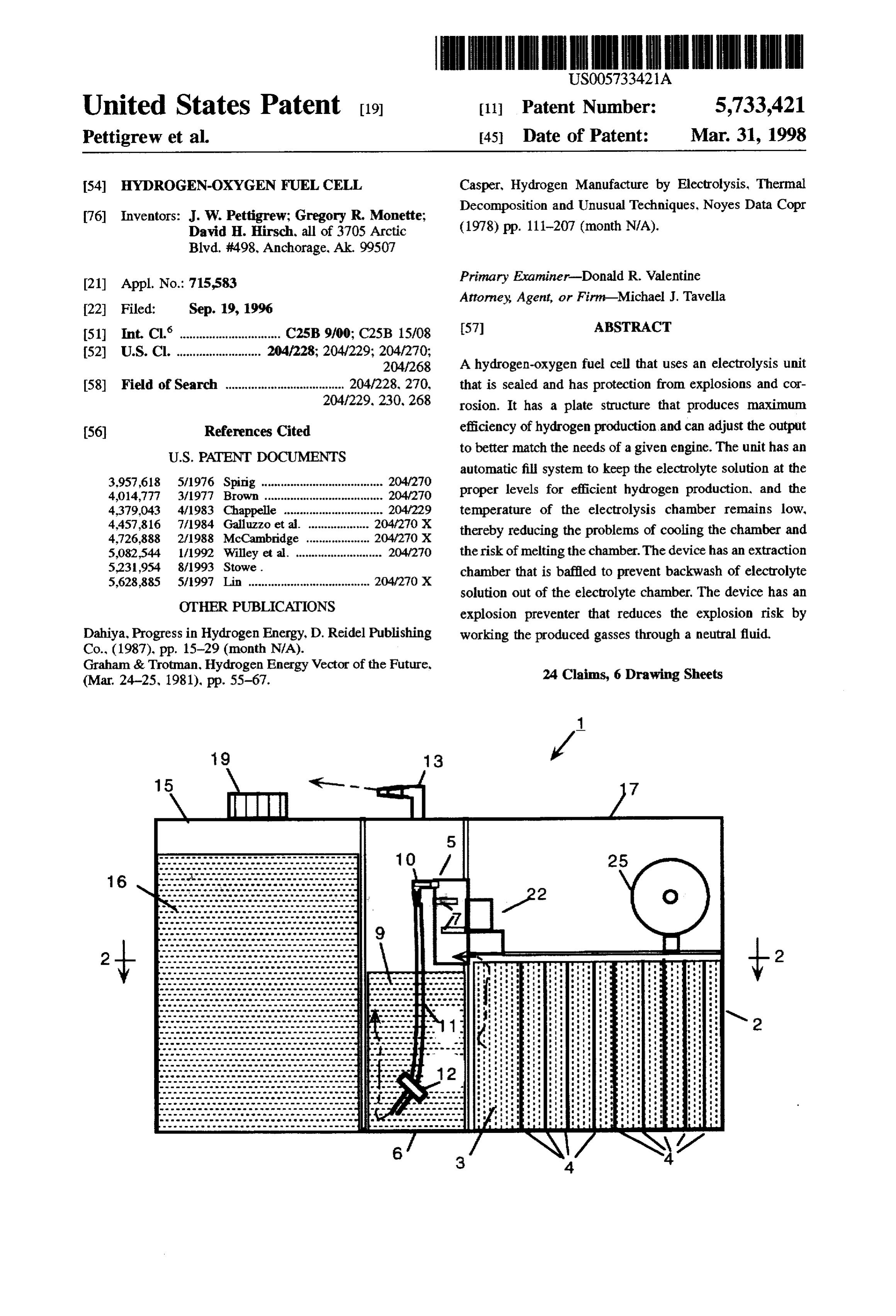
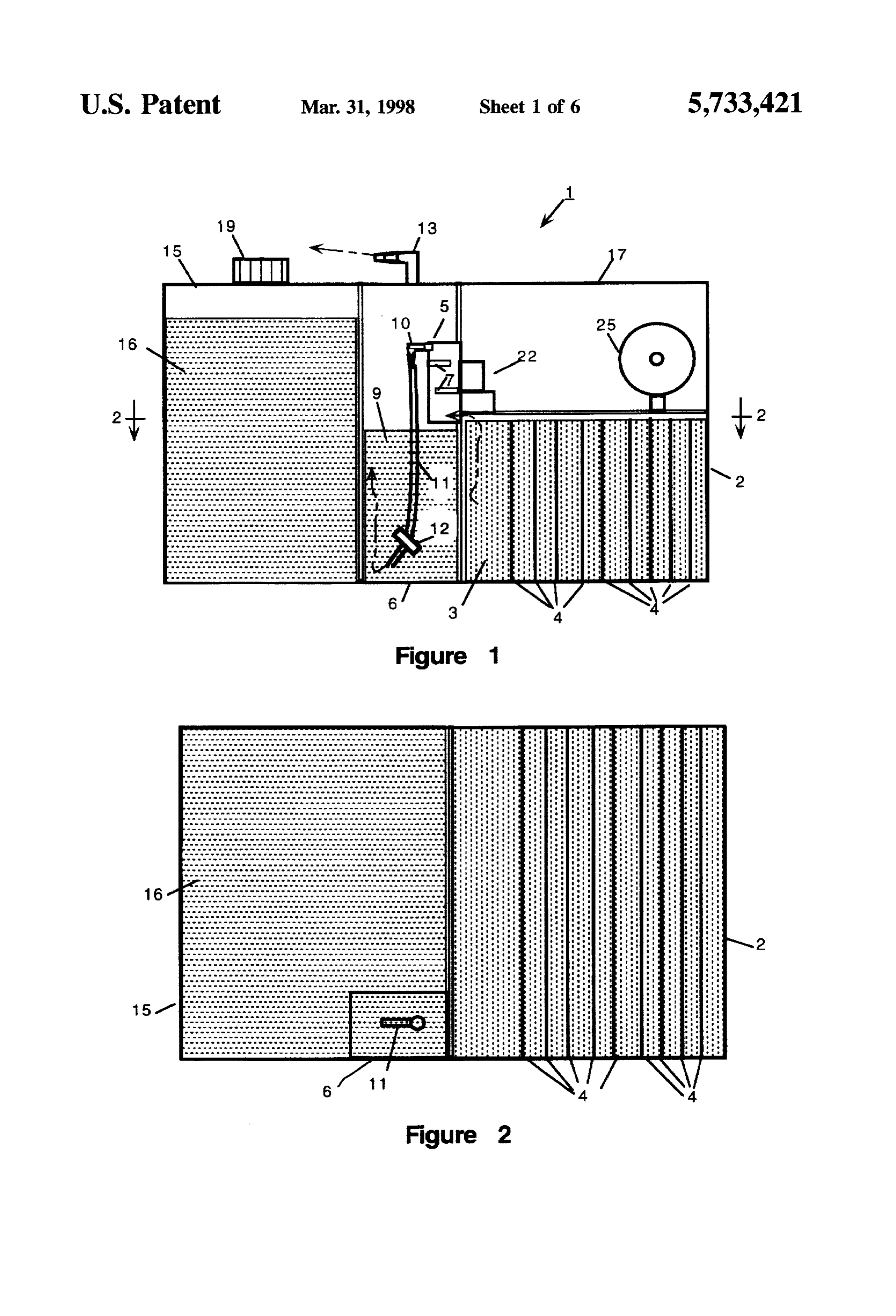
It is a further object of this invention to produce a check valve 12 that prevents back flow of gas or fluid 9 hydrogen-oxygen fuel cell that keeps the operating tempera through the hose 11. At the top of the EPS 6 is an outlet port ture of the electrolysis chamber low, thereby reducing the 13, through which the hydrogen and oxygen gasses are problems of cooling the electrolysis chamber and the risk of removed and passed into the engine as discussed below. The melting the electrolysis chamber. next compartment is the water tank 15. The water tank 15 is It is another object of the invention to provide a hydrogen designed to hold replacement water 16 for the unit. This oxygen fuel cell that delivers a constant level of hydrogen to water 16 is automatically replaced from the water tank 15 to a vehicle. the electrolysis chamber 2 as needed. The operating system for this is discussed below. The fourth compartment is the
It is yet another object of the invention to provide a control module 17, which is a sealed unit that houses all the hydrogen-oxygen fuel cell that has a control to adjust the 10 controls.
output of the fuel cell to produce an optimum amount of below. These controls are discussed in greater detail hydrogen for any size of engine.
It is yet a further object of this invention to produce a along FIG. 2 is a top detail view of the lower housing, taken hydrogen-oxygen fuel cell in which the automatic fill system 15 the EPSthe lines 2-2 of FIG.1. This shows the placement of is also designed to prevent overfill of the electrolysis cham All the 6,compartments the electrolysis chamber 2 and the water tank 15.
are sealed and made from a high ber if the vehicle is not level.
strength molded plastic, in the preferred embodiment. Plas
It is yet another object of this invention to produce a tic is preferred so that a user can see the fluid levels easily hydrogen-oxygen fuel cell that has an extraction chamber and can refill the water tank 15 when needed, through the fill that is baffled to prevent back wash of electrolyte solution port 19 cap (see, e.g., FIG. 1).
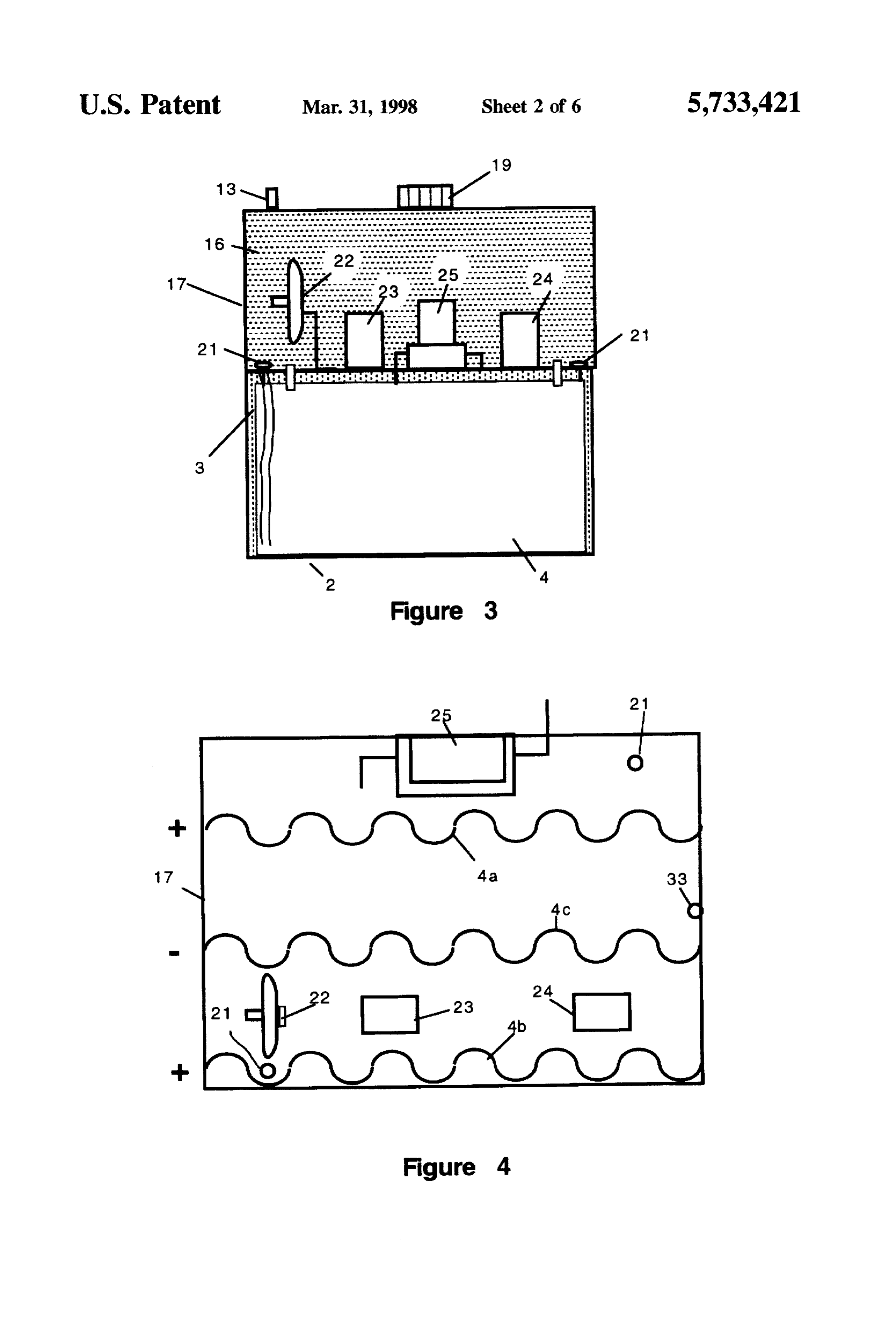
out of the electrolyte chamber. FIG. 2 also shows the placement of the electrolysis plates It is another object of this invention to produce a 4. In this figure, the plates 4 are shown as being straight hydrogen-oxygen fuel cell that has an explosion preventer rectangles. Although this shape can be used, the corrugated that reduces the explosion risk by bubbling the produced shape of FIG. 9 is preferred, this preference is discussed gasses through a neutral fluid. 25 below when the plate structure is discussed in detail.
It is a further object of this invention to produce a FIG. 3 is a right side view of the fuel cell 1. FIG. 4 is a hydrogen-oxygen fuel cell that uses conductive tape on the top view of the control section, showing the main plates 4. cover of the device to shut down the electrical supply to the The electrolyte level sensors 21, the vacuum switch 22, relay device if the device suffers catastrophic failure. 30 one 23, relay two 24 and the solenoid activated gate valve BRIEF DESCRIPTION OF THE DRAWINGS 25 are shown. FIG.3 also shows the water tank fill cap 19. As shown in FIG. 4, the plates 4 are corrugated. This
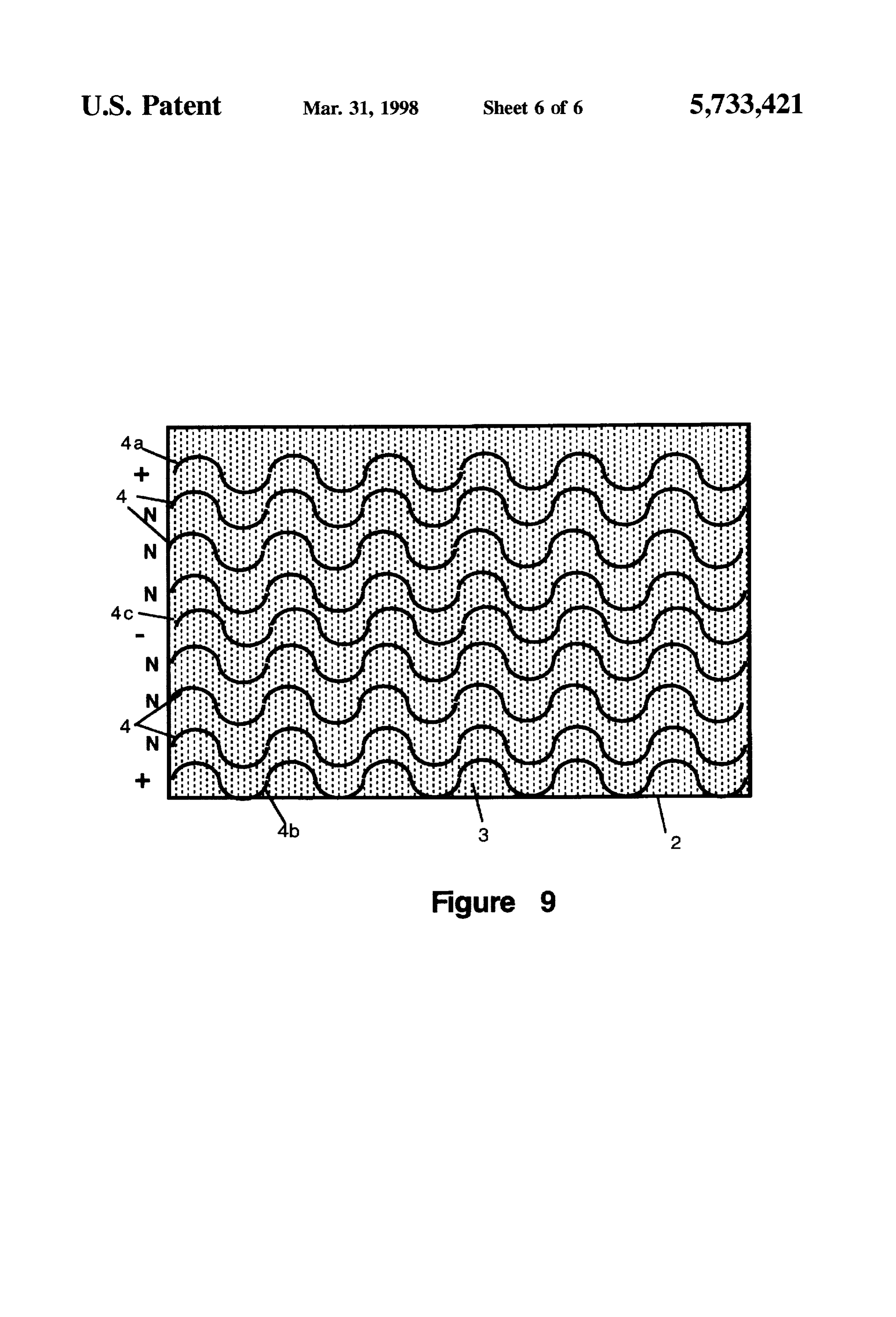
FIG. 1 is a side view of the invention. permits a larger plate area to be housed in a smaller vessel. FIG. 2 is a top sectional view of the invention taken along In the preferred embodiment, three charged plates 4a, 4b, the lines 2-2 of FIG. 1. 35 and 4c are used along with six neutral plates N to form the FIG. 3 is a right side elevation view of the invention. plate grid (see FIG. 9). The number of plates 4 can be FIG. 4 is a partial top view of the invention showing the increased or decreased, but the efficiency of the device control module. declines. If fewer plates 4 are used, the time needed to build production of the gasses increases. Moreover, the tempera
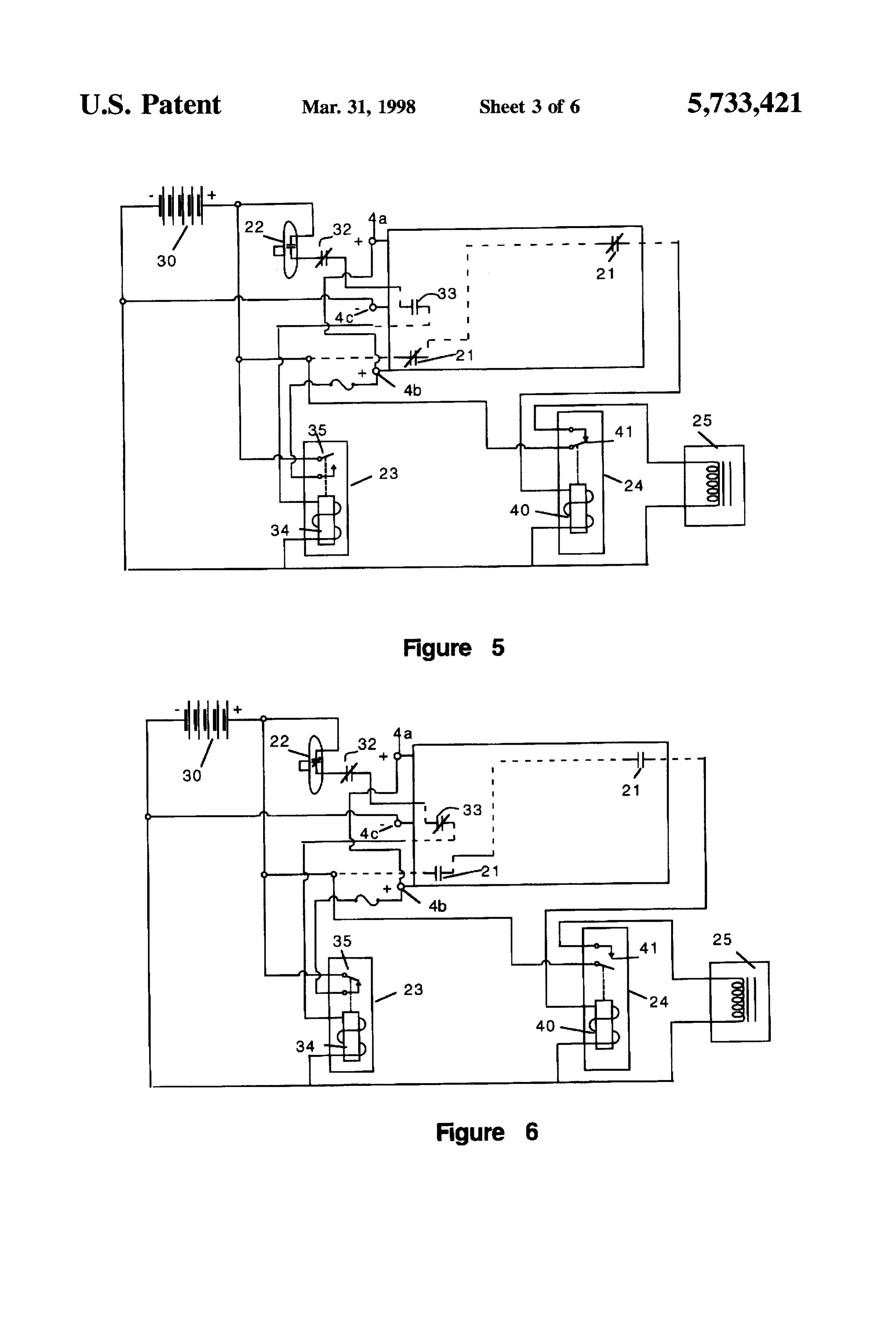
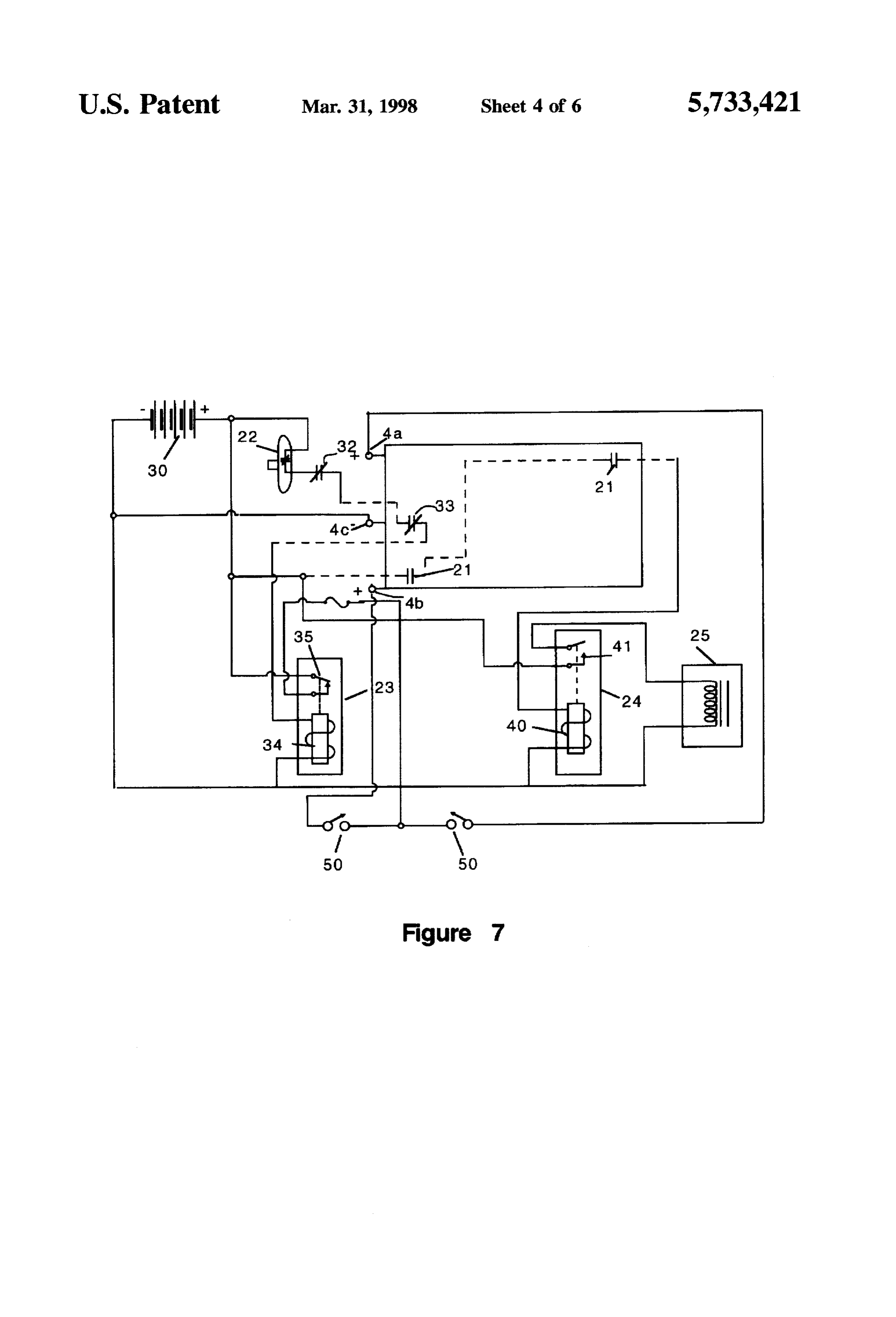
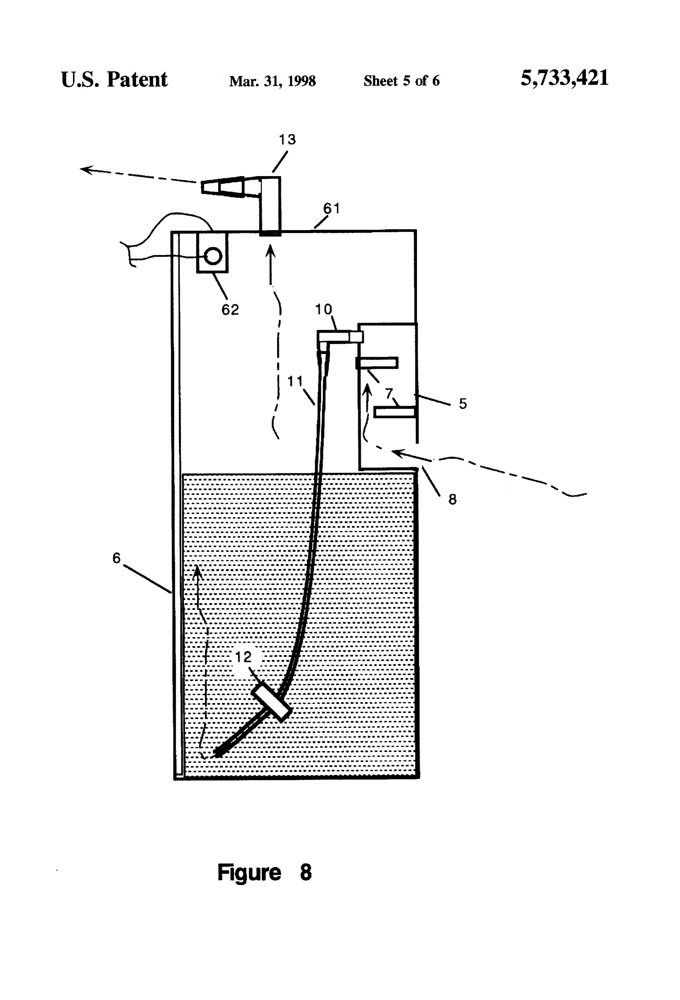
FIG. 5 is a schematic diagram of the operating circuits of ture of the device runs higher. If more plates than optimum the system in an "off" mode with the electrolyte chamber are used, the spacing of the plates 4 may be too small. The empty. small gap slows production because the released gas bubbles FIG. 6 is a schematic diagram of the operating circuits of take longer to rise through a narrow chamber, thereby the system in an "on" mode with the electrolyte chamber restricting the flow of electrolyte between the plates 4. This full. 45 also decreases production. We have found a spacing of FIG. 7 is a schematic diagram of the operating circuits of between about 0.375 and 0.5 inches between the plates 4 to the system showing an alternative power distribution be optimum. At this spacing, the escaping bubbles do not scheme. interfere with gas production. At the same time, the plates 4 FIG. 8 is an enlarged side view of the gas removal path are close enough together to maintain a high degree of gas and explosion preventer system. production.
FIG. 9 is a top view of the preferred plate layout and The controls consist of two main circuits. FIGS. 3 and 4 structure. show the layout of the control elements. FIGS. 5, 6 and 7 show the electrical schematic diagrams of the circuits at two
DETALED DESCRIPTION OF THE different states. Both circuits are operated from a battery INVENTION 55 power source 30. This can be a vehicle battery or an
Referring now to FIG. 1, the side view of the fuel cell 1 auxiliary battery as desired. FIG. 5 shows the system in the is shown. The fuel cell 1 has four main compartments. The off mode. Of the two circuits, the first circuit is the gas first is the electrolysis chamber 2. This is the chamber that production circuit. Power is fed from the positive terminal of holds the electrolyte solution 3 and the stainless steel plates the battery 30 to a vacuum switch 22. This switch is 4 that are used to produce the hydrogen and oxygen. The normally open and closes when engine vacuum is applied to second compartment is the exhaust gas plenum 5 and the the switch. In this way, the device does not produce gas if the explosion preventer system (EPS) 6 (see also FIG. 4). This engine is off and the ignition is accidentally left on. The module has the exhaust plenum 5, which has two baffles 7 power then flows through an emergency shut down circuit and a port 8. The EPS 6 is a compartment that is filled with 32, which is discussed below. This circuit is normally a fluid 9. A nipple 10 transfers the gas from the plenum 5 to 65 closed. From there, the power feeds to a low fluid cutoff a hose 11 as shown. The hose 11 extends down to the bottom switch 33 that is normally open. From there, the powerflows of the EPS chamber 6. At the end of the hose 11 is a one way to the coil 34 of relay one 23. The other lead of the coil 34
Page 10
S 6 feeds to the negative terminal of the battery 30. Relay one Corporation of St. Paul, Minn. This tape acts as the normally 23 is a normally open relay. When power is fed to the coil closed contact 32 of FIGS. 5, 6 and 7. If the top 61 blows 34, the contacts 35 of relay one 23 close. That puts positive off, the tape 62 tears and opens the circuit to the electrolyte voltage from the battery 30 to the positive plates 4a and 4b chamber 2, thereby shutting down gas production, prevent a shown. The negative terminal of the battery 30 is directly ing possible further explosions. An alternative to the tape is connected to the center plate 4c. In the preferred a wire 62 that is embedded in the plastic walls of the embodiment, the charged plates 4a, 4b, and 4c are bolted to housing. Here, if the wire breaks, the circuit is shut down. Of the floor of the control module 17. course, any other breakable type contact device or system The second circuit is the electrolyte level circuit. This can be used to achieve the same purpose. circuit is designed to prevent the electrolyte level in the 10 FIG.9 shows the preferred arrangement of plates 4 within electrolyte chamber from dropping below the optimum the electrolyte chamber 2. As discussed above, three charged level. If this occurs, the temperature of the device tends to plates 4a, 4b, and 4c are placed as shown. Six neutral plates rise and gas production drops. To prevent these conditions, 4b, and 4c to "N" 4 and labeled are placed between the charged plates 4a, maximize gas production.
circuit two provides a means of automatically maintaining water levels in the electrolyte chamber. In this circuit, 5 There are a wide variety of solutions that can be used as positive battery 30 is connected to a number of level sensors electrolyte solution 3. Some examples of electrolyte solu 21 through the plates 4a and 4b. Because the sensors receive tions are: Potassium Hydroxide, Potassium Nitrate. Sodium positive battery 30 from the plates 4a and 4b, the sensors are Sulfate and Sulfuric Acid. Of these, Potassium Hydroxide is placed around the perimeter of the electrolyte chamber (see, O preferred. Sulfuric Acid produces the largest quantity of e.g., FIG. 4) in alignment with the plates 4a and 4b. These Hydrogen per unit volume, but is highly corrosive and sensors 21 are normally closed when the electrolyte chamber quickly destroys the plate material. Potassium Hydroxide 3 is empty. When the electrolyte 3 level is at maximum, the produces a good supply of hydrogen while not damaging the level sensors 21 are open. The level sensors 21 are connected plates. The Potassium Hydroxide is mixed with water to in series to the coil 40 of relay two 24. The other end of coil 25 form the electrolyte solution 3. Once in place, only addi 40 goes to negative. The contacts 41 of relay two 40 are tional water is needed to continue the hydrogen production. normally open. When coil 40 is energized, the contacts 41 This water 16 is supplied from the water tank 15, as close, thereby applying power to the solenoid activated gate discussed above.
valve 25, which opens. Because vacuum is being applied to The device is used by filling the chambers with fluid, as the unit, water flows from the water tank 15 into the appropriate, connecting the circuitry and starting the vehicle. electrolyte chamber 2. When the electrolyte 3 level is again 30 Gas production begins and feeds into the engine from the at its maximum, the level sensors 21 all open. That causes exhaust port 13.
power to be cut to relay two, shutting the solenoid activated The present disclosure should not be construed in any gate valve 25. Placement of the level sensors 21 allows the limited sense other than that limited by the scope of the unit to be off level without causing the solenoid activated 35 claims having regard to the teachings herein and the prior art gate valve 25 to be open. If the device is off level, at least being apparent with the preferred form of the invention one of the level sensors 21 is covered with liquid. As long disclosed herein and which reveals details of structure of a as one sensor remains covered with liquid, the solenoid preferred form necessary for a better understanding of the activated gate valve 25 cannot be opened. invention and may be subject to change by skilled persons In one embodiment, the level sensors 21 are simple within the scope of the invention without departing from the screws that are fastened to the top of the electrolyte chamber. concept thereof.
I claim:
The screws are in proximity to the plates 4a and 4b. Because of this proximity, the positive voltage from the plates is 1. A hydrogen-oxygen fuel cell comprising: picked up by the screws when the electrolyte levels are low. a) an electrolysis chamber, adopted to contain electrolyte, As such, the screws are positively charged at low electrolyte 45 and having a perimeter;
levels, which causes the automatic fill circuit to become b) a plurality of plates, installed within said electrolysis energized. chamber;
F.G. 6 shows the schematic of the device with all fluids c) a means for applying an electrical charge to said at operating levels and the vehicle and fuel cell 1 in plurality of plates;
operation. 50 d) means for sensing a level of electrolyte solution within FIG. 7 shows an alternative wiring plan. In this system, said electrolysis chamber, wherein the means for sens two switches 50 are provided to separate power to the ing a level of electrolyte solution within said electroly positive plates 4a and 4b. Using the switches 50, either sis chamber comprises a plurality of level sensors, positive plate or both positive plates may be energized. spaced about the perimeter of the electrolysis chamber; These switches 50 allow the fuel cell's 1 output to be 55 e) a means for automatically refilling said electrolysis adjusted as desired from 2 production to full production. In chamber with water, this way, the unit can be optimized for any size vehicle f) control means, operably connected to said means for quickly and easily. sensing, to operate said means for automatically refill Referring now to FIG. 8, details of the gas discharge and ing; and
EPS 6 are shown. As discussed above, the gas produced g) a means for extracting hydrogen and oxygen produced moves through the EPS 6 as shown. The top 61 of the EPS in said electrolysis chamber. 6 is not sealed. It is placed so that ordinary pressures do not 2. The hydrogen-oxygen fuel cell of claim 1 further cause the top 61 to come of the unit. However, an explosive comprising a means for preventing a flash back explosion. force blows the top 61 from the unit. As discussed above, an 3. The hydrogen-oxygen fuel cell of claim 2 wherein said explosion power cutoff is provided. This can consist of a 65 means for preventing a flash back explosion comprises: strip of metallic conduction tape 62 and leads 63, such as a) a flash back preventer chamber, said flash back cham that used in burglar alarms. This tape is available from 3M ber adopted to contain a quantity of liquid;
Page 11
b) an inlet port, attached to said means for extracting b) a means for transporting the quantity of water from said hydrogen and oxygen, wherein said inlet port includes vessel to said electrolysis chamber; an extraction nipple that enters into said flash back c) a valve, operably placed within said means for trans preventer chamber; porting the quantity of water from said vessel to said c) a hose, fixedly attached to said extraction nipple, electrolysis chamber, such that said valve operates to having a free end that extends downwardly therefrom control a flow of said quantity of water; and into said flash back preventer chamber, wherein said d) a means for controlling said valve, in electrical com hose is positioned such that when said quantity of munication with said valve and said plurality of level liquid fills said flash back preventer chamber, said SCSOTS quantity of liquid reaches a level sufficient to cover the 10 15. The hydrogen-oxygen fuel cell of claim 1 wherein the free end of said hose; and control means to operate said means for automatically d) a check valve; operably attached to the free end of said refilling includes a switchable relay. hose to prevent a backflow of the quantity of liquid into 16. The hydrogen-oxygen fuel cell of claim 1 wherein the the hose. means for extracting hydrogen and oxygen produced in said 4. The hydrogen-oxygen fuel cell of claim 3 wherein the 5 electrolysis chamber includes a baffled exhaust chamber. means for controlling an application of an electric charge to 17. A hydrogen-oxygen fuel cell comprising: said plurality of plates includes an emergency cutoff switch. a) an electrolysis chamber, adopted to contain electrolyte, 5. The hydrogen-oxygen fuel cell of claim 4 wherein the and having a perimeter;
emergency cutoff switch comprises a piece of electoconduc tive tape placed on the flash back preventer chamber, b) a plurality of plates, installed within said electrolysis whereby if said backflash preventer chamber ruptures, said chamber;
piece of electoconductive tape is torn, thereby breaking an c) a battery, in electrical communication with said plu electric circuit to said plurality of plates. rality of plates, thereby imparting an electrical charge 6. The hydrogen-oxygen fuel cell of claim 4 wherein the on said plurality of plates;
emergency cutoff switch comprises a piece of wire embed d) a plurality of level sensors, spaced about the perimeter ded in the flash back preventer chamber, whereby if said of the electrolysis chamber; back flash preventer chamber ruptures, said piece of wire is e) a vessel, adopted to contain a quantity of water; broken, thereby breaking an electric circuit to said plurality f) a means for transporting the quantity of water from said of plates. vessel to said electrolysis chamber; 7. The hydrogen-oxygen fuel cell of claim 4 wherein the emergency cutoff switch further includes a low fluid level g) a valve, operably placed within said means for trans cutoff switch, said low fluid level cutoff having sensing porting the quantity of water from said vessel to said means where by when said sensing means detects that the electrolysis chamber, such that said valve operates to quantity of electrolyte solution in said electrolysis chamber control the flow of said quantity of water; has reached a low level, power is removed from said 35 h) a means for controlling said valve. in electrical com plurality plates. thereby shutting off the hydrogen-oxygen munication with said valve and said plurality of level fuel cell. sensors;
8. The hydrogen-oxygen fuel cell of claim 1 further i) a baffled exhaust chamber, in gaseous communication comprising a means for controlling an application of an with said electrolysis chamber; electric charge to said plurality of plates. j) a flash back preventer chamber adopted to contain a 9. The hydrogen-oxygen fuel cell of claim 8 wherein the quantity of liquid;
means for controlling an application of an electric charge to k) an inlet port attached to said means for extracting said plurality of plates includes a vacuum operated switch. hydrogen and oxygen, wherein said inlet port includes 10. The hydrogen-oxygen fuel cell of claim 1 wherein the an extraction nipple that enters into said flash back means for applying an electrical charge to said plurality of 45 preventer chamber;
plates comprises a battery.
11. The hydrogen-oxygenfuel cell of claim 1 wherein said 1) a hose, fixedly attached to said extraction nipple, having plurality of plates are corrugated. a free end that extends downwardly therefrom into said 12. The hydrogen-oxygen fuel cell of claim 1 wherein flash back preventer chamber, wherein said hose is said plurality of plates are arranged in a pattern comprising: 50 positioned such that said quantity of liquid, fills said a first outer plate, being positively charged; a second outer flash back preventer chamber, said quantity of liquid plate, being positively charged; a central plate, being nega reaches a level sufficient to cover the free end of said tively charged; at least one neutral plate, spaced between hose; and said first outer plate and said central plate; and at least one m) a check valve; operably attached to the free end of said neutral plate, spaced between said second outer plate and 55 hose to prevent a backflow of the quantity of liquid into said central plate. the hose.
13. The hydrogen-oxygen fuel cell of claim 12 further 18. The hydrogen-oxygen fuel cell of claim 17 further comprising a means for controlling an application of charge comprising an emergency cutoff switch. to said plurality of plates is selectable from the following 19. The hydrogen-oxygen fuel cell of claim 18 wherein configurations: said first outer plate is energized and said the emergency cutoff switch comprises a piece of electo second outer plate is not energized; said first outer plate is conductive tape placed on the flashback preventer chamber, not energized and said second outer plate is energized; and whereby if said flash back preventer chamber ruptures, said wherein both outer plates are energized. piece of electoconductive tape is torn, thereby breaking an 14. The hydrogen-oxygen fuel cell of claim 1 wherein the electric circuit to said plurality of plates. means for automatically refilling said electrolysis chamber 65 20. The hydrogen-oxygen fuel cell of claim 18 wherein with water comprises: the emergency cutoff switch comprises a piece of wire a) a vessel, adopted to contain a quantity of water; embedded in the flash back preventer chamber, whereby if
Page 12
said flash back preventer chamber ruptures, said piece of a first outer plate, being positively charged; a second outer wire is broken, thereby breaking an electric circuit to said plate, being positively charged; a central plate, being nega plurality of plates. tively charged; at least one neutral plate, spaced between 21. The hydrogen-oxygen fuel cell of claim 18 wherein said first outer plate and said central plate; and at least one the emergency cutoff switch further includes a low fluid neutral plate, spaced between said second outer plate and level cutoff switch, said low fluid level cutoff having sensing said central plate.
means whereby when said sensing means detects that the 24. The hydrogen-oxygen fuel cell of claim 23 further quantity of electrolyte solution in said electrolysis chamber comprising a means for controlling an application of charge has reached a low level, power is removed from said to said plurality of plates is selectable from the following plurality plates, thereby shutting off the hydrogen-oxygen 10 configurations: said first outer plate is energized and said fuel cell. second outer plate is not energized; said first outer plate is 22. The hydrogen-oxygen fuel cell of claim 17 wherein not energized and said second outer plate is energized; and said plurality of plates are corrugated. wherein both outer plates are energized. 23. The hydrogen-oxygen fuel cell of claim 17 wherein said plurality of plates are arranged in a pattern comprising: :k : k is sk

Provenance
- Collection
- Cited prior art
- Original PDF
- patentimages.storage.googleapis.com →
- Filed
- 1996-09-19
- Pages
- 12
- Method
- pdftotext (the PDF's own text layer) + pdftoppm 300dpi page scans
- Source
- Google Patents bibliographic record
- Granted
- 1998-03-31
- Inventors
- J. W. Pettigrew; Gregory R. Monette; David H. Hirsch
- Transcribed from
- patentimages.storage.googleapis.com →