patent · US20020179453A1
Hydrogen producing apparatus
5 December 2002
Page 1 — bibliographic record
(19) United States (12) Patent Application Publication (10) Pub. No.: US 2002/0179453 A1
Chambers (43) Pub. Date: Dec. 5, 2002 (54) HYDROGEN PRODUCING APPARATUS (52) U.S. Cl. ......................... 205/628; 205/104; 205/108;
(76) Inventor: Stephen Barrie Chambers, Calgary
(CA) (57) ABSTRACT
Correspondence Address:
STOEL RIVES LLP An apparatus for producing orthohydrogen and/or parahy 900 SW FIFTHAVENUE drogen. The apparatus includes a container holding water SUTE 2600 and at least one pair of closely-spaced electrodes arranged PORTLAND, OR 97204 (US) within the container and Submerged in the water. A first power Supply provides a particular first pulsed signal to the (21) Appl. No.: 10/183,855 electrodes. A coil may also be arranged within the container and Submerged in the water if the production of parahydro (22) Filed: Jun. 25, 2002 gen is also required. A Second power Supply provides a Second pulsed signal to the coil through a Switch to apply
Related U.S. Application Data energy to the water. When the Second power Supply is disconnected from the coil by the Switch and only the (63) Continuation of application No. 09/608,316, filed on electrodes receive a pulsed Signal, then orthohydrogen can Jun. 30, 2000, now Pat. No. 6,419,815, which is a be produced. When the Second power Supply is connected to continuation of application No. 09/105,023, filed on the coil and both the electrodes and coil receive pulsed Jun. 26, 1998, now Pat. No. 6,126,794. Signals, then the first and Second pulsed Signals can be controlled to produce parahydrogen. The container is Self
Publication Classification preSSurized and the water within the container requires no chemical catalyst to efficiently produce the orthohydrogen (51) Int. Cl. .............................. C25D 5/18; C30B 7/12; and/or parahydrogen. Heat is not generated, and bubbles do not form on the electrodes.
FNTERNA
COMBUSTION
ENGINE
TAP WATER
INTERACTION ZONE
ELECTRODE
PULSES ULL
Page 2
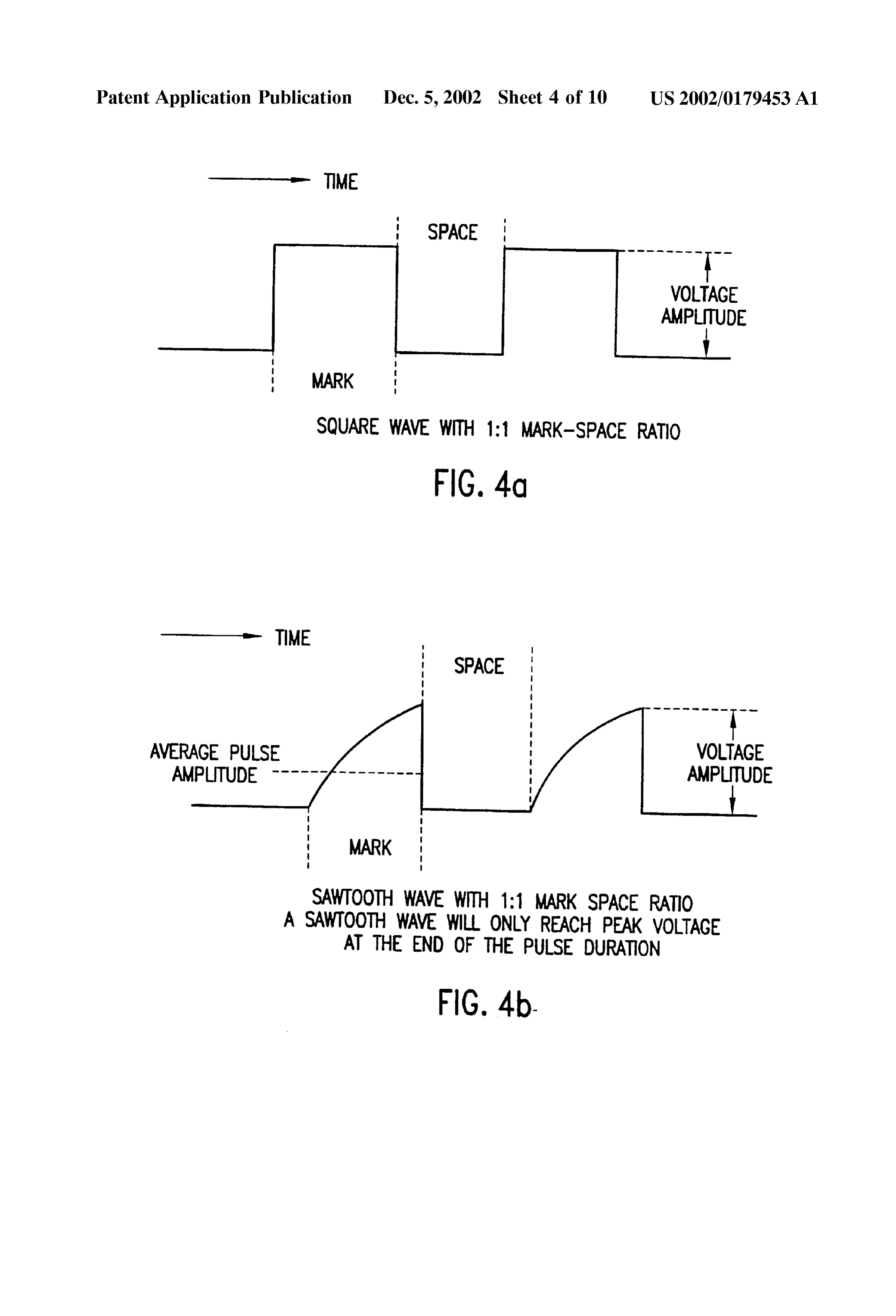
Drawing sheet — no readable text.
Page 3
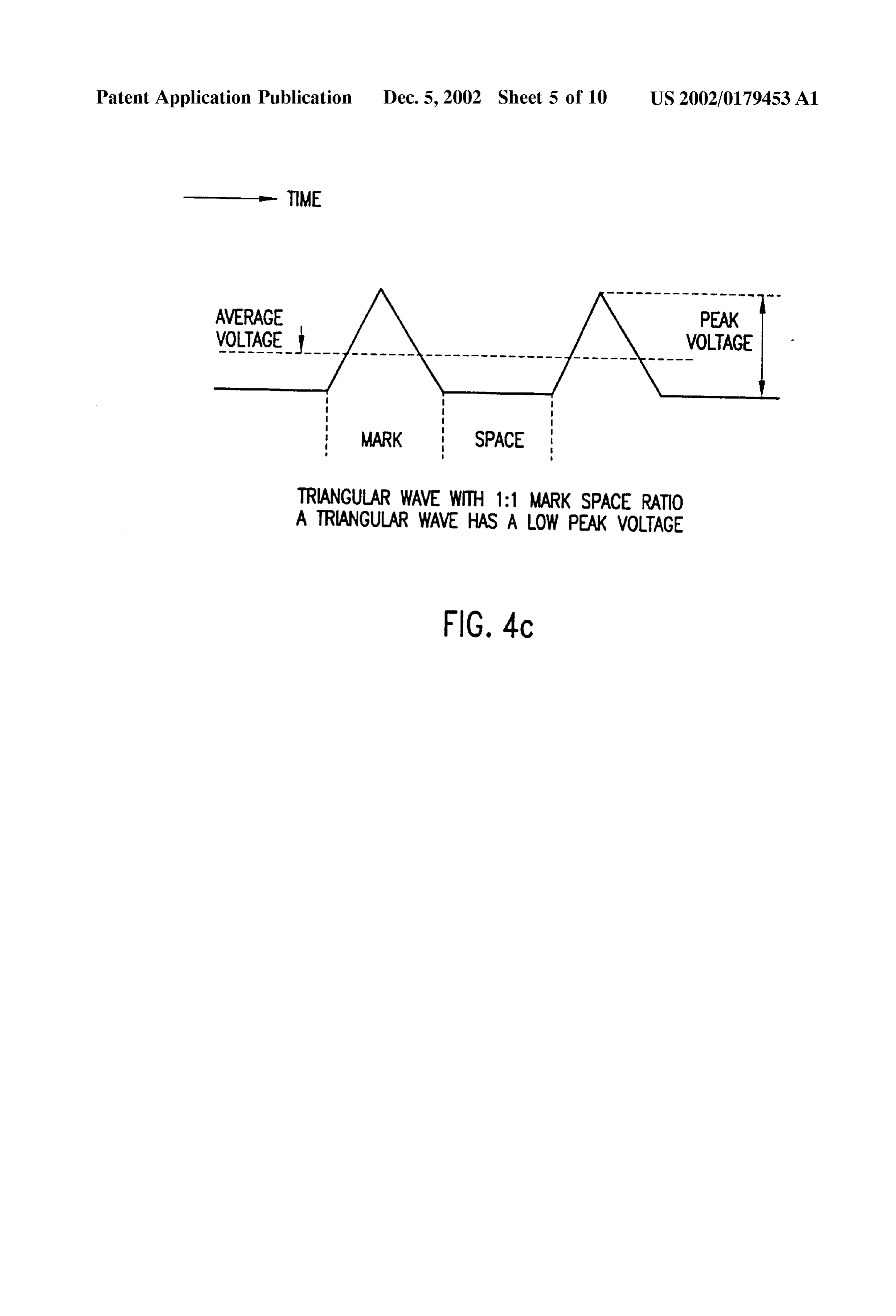
Drawing sheet — no readable text.
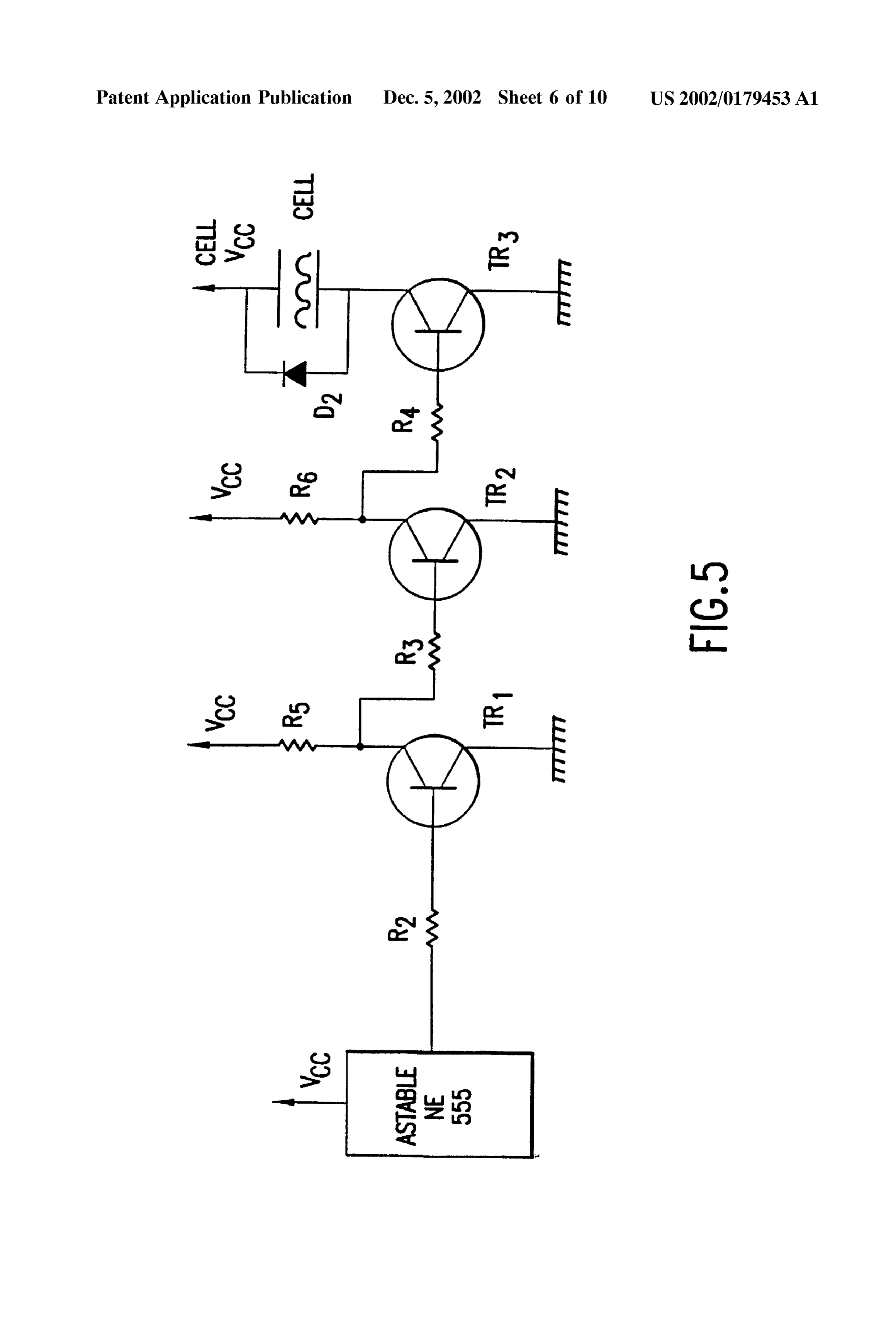
Page 4
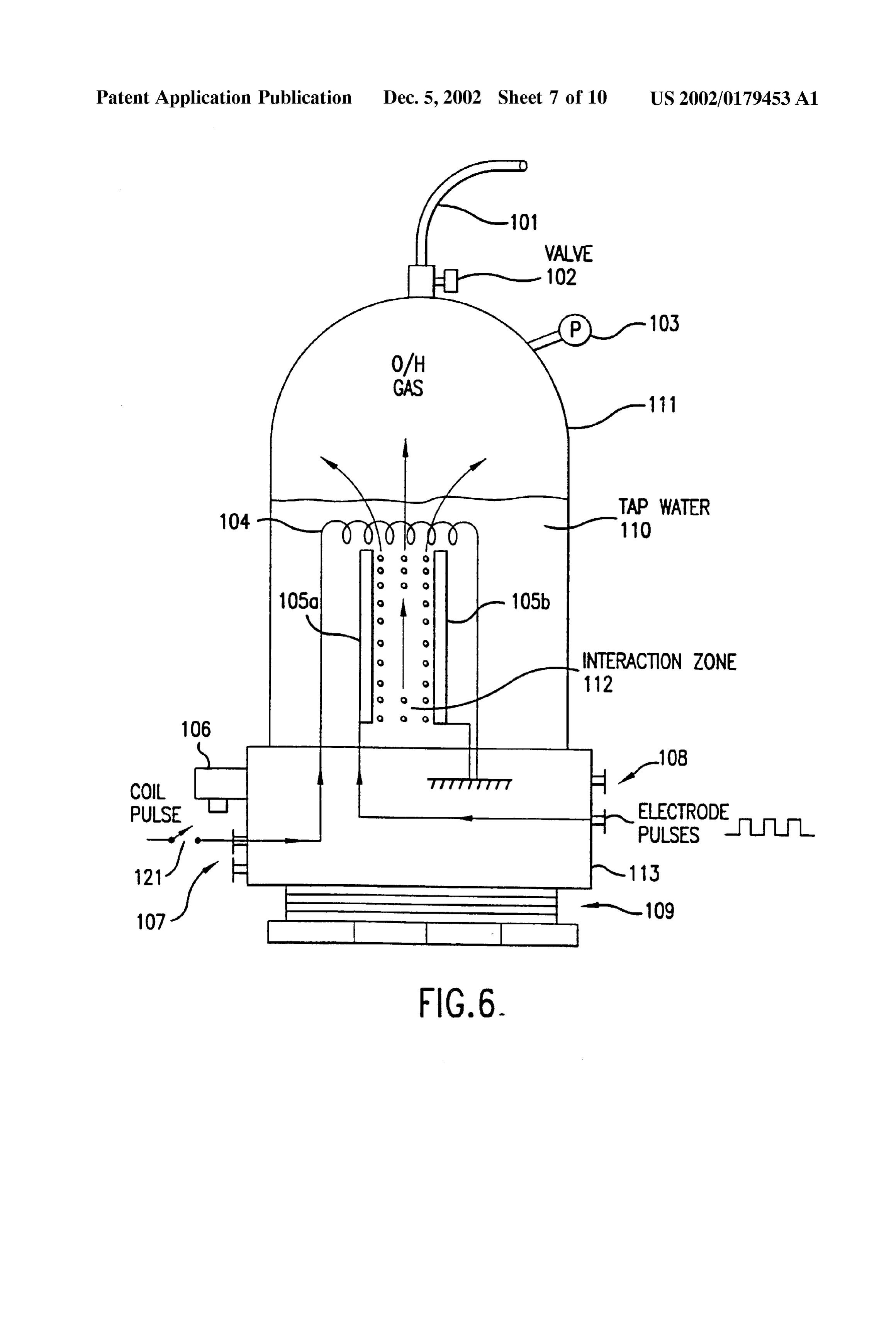
Drawing sheet — no readable text.
Page 5
Patent Application Publication Dec. 5, 2002 Sheet 4 of 10 US 2002/0179453 A1
TIME
SPACE
VOLTAGE
AMPLTUDE
MARK
SQUARE WAVE WITH 1:1 MARK-SPACE RATIO
FIG. 4d
TIME
: SPACE
AVERAGE PULSE wa
AMPTUDE
MARK
SAWTOOTH WAVE WITH 1:1 MARK SPACE RATIO
A SAWTOOTH WAVE WILL ONLY REACH PEAK VOLTAGE
AT THE END OF THE PULSE DURATION
FIG. 4b.
Page 6
Patent Application Publication Dec. 5, 2002. Sheet 5 of 10 US 2002/0179453 A1
-- TIME
AVERAGE PEAK VOLTAGE VOLTAGE
MARK SPACE
TRANGULAR WAVE WITH 1:1 MARK SPACE RATIO
A TRANGULAR WAVE HAS A LOW PEAK VOLTAGE
FIG. 4C
Page 7
Drawing sheet — no readable text.
Page 8
Drawing sheet — no readable text.
Page 9
Drawing sheet — no readable text.
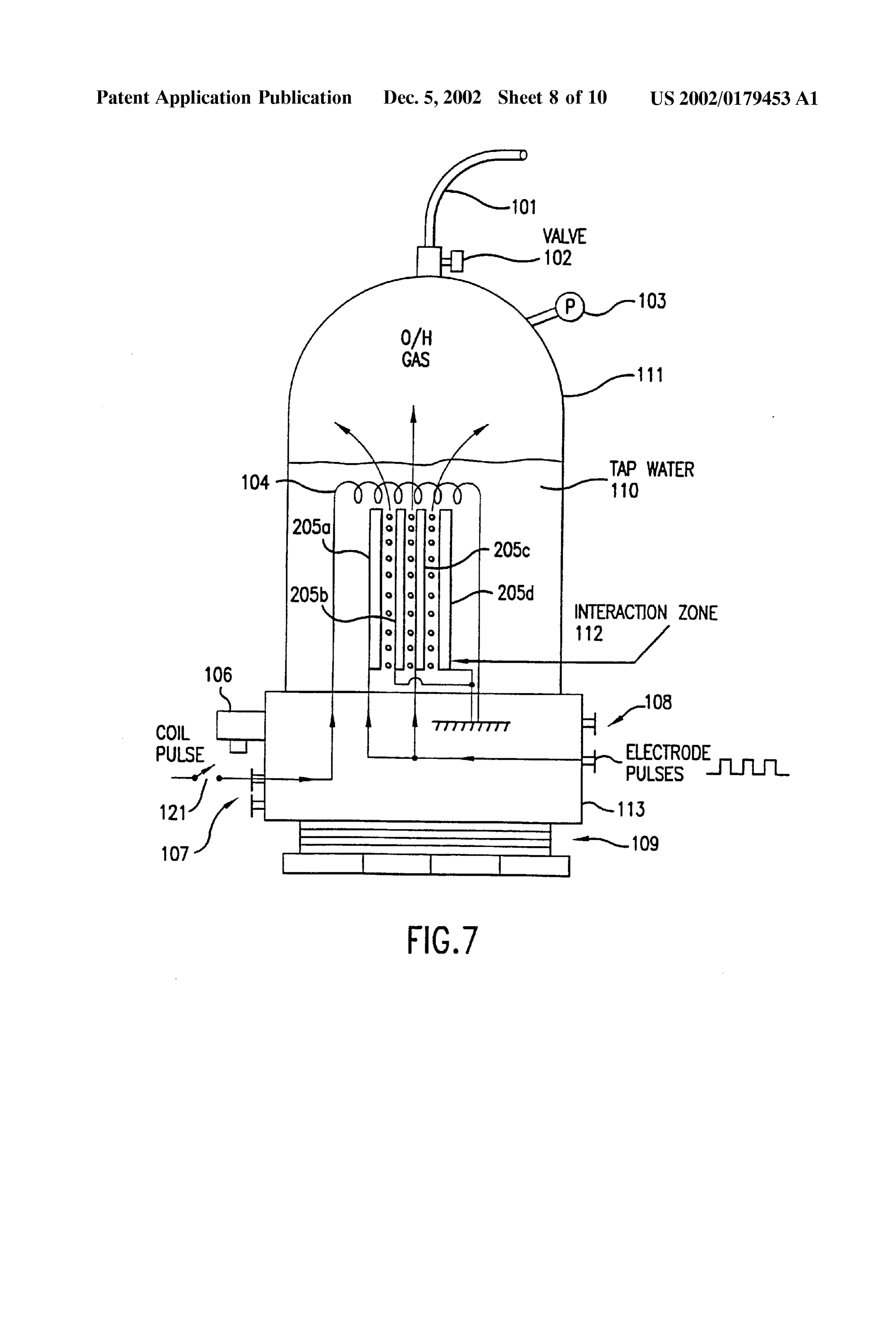
Page 10
Drawing sheet — no readable text.
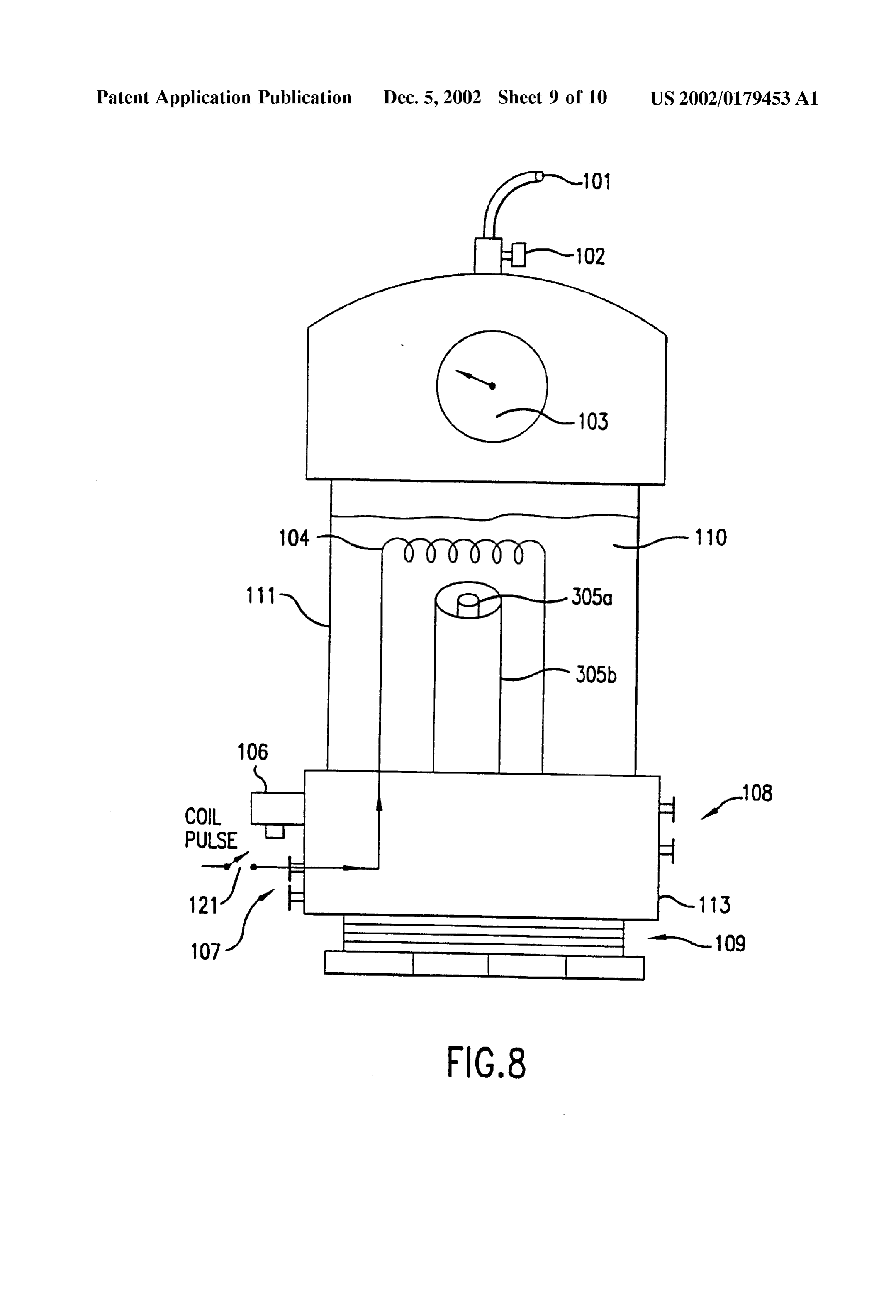
Page 11
Drawing sheet — no readable text.
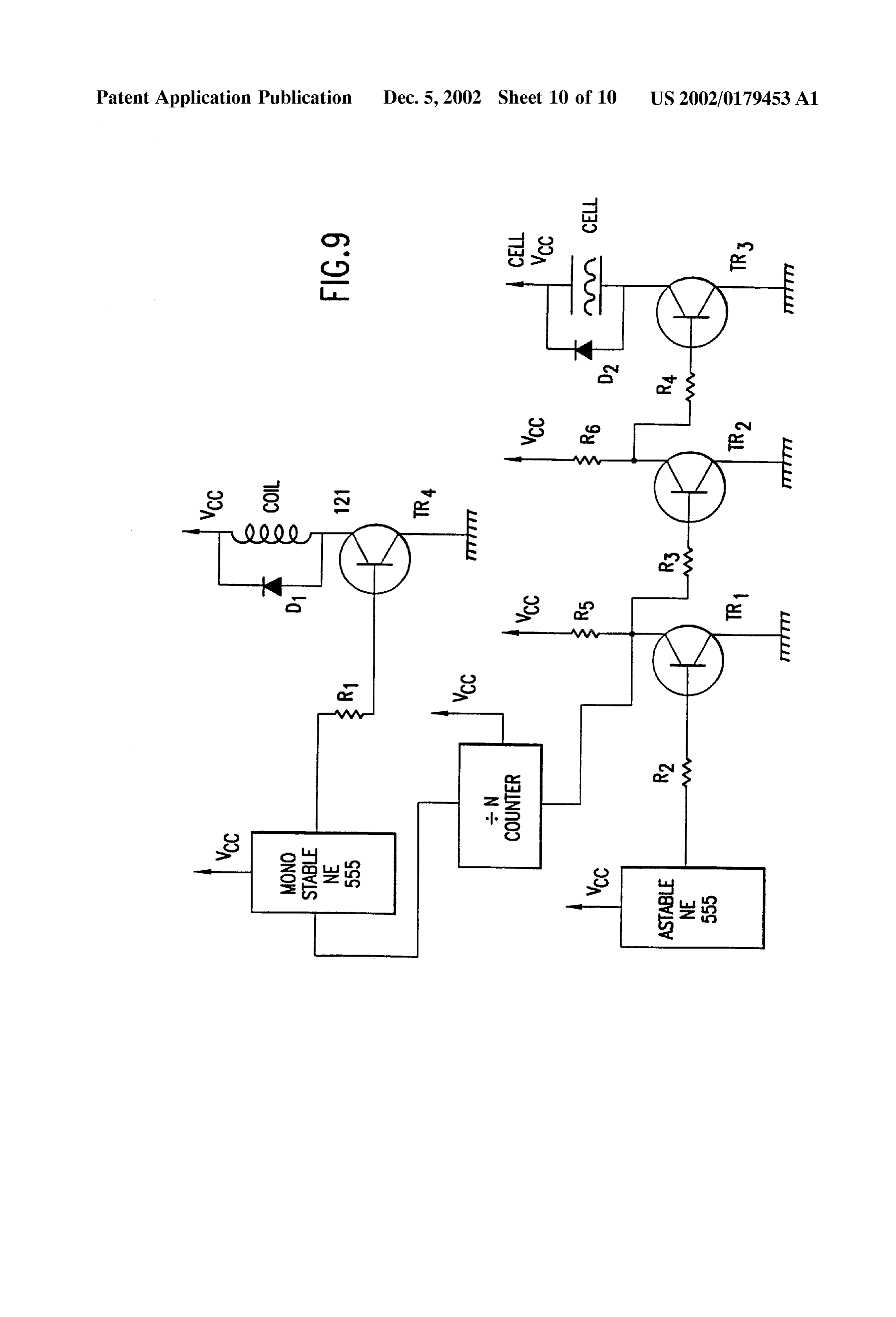
Page 12
US 2002/0179453 A1 Dec. 5, 2002
HYDROGEN PRODUCING APPARATUS relatively Small amount of time, and with a modest amount of input power, and without generating heat.
TECHNICAL FIELD
0008. It is another object of the present invention for the 0001. The present invention relates to methods for pro cell to produce bubbles of hydrogen and oxygen which do ducing orthohydrogen and parahydrogen. not bunch around or on the electrodes.
BACKGROUND OF THE INVENTION 0009. It is also an object of the present invention for the cell to properly operate without a chemical catalyst. Thus, 0002 Conventional electrolysis cells are capable of pro the cell can run merely on tap water. Moreover, the addi ducing hydrogen and oxygen from water. These conven tional costs associated with the chemical catalyst can be tional cells generally include two electrodes arranged within avoided.
the cell which apply energy to the water to thereby produce 0010. It is another object of the present invention for the hydrogen and oxygen. The two electrodes are convention cell to be Self-pressurizing. Thus, no additional pump is ally made of two different materials. needed.
0003. However, the hydrogen and oxygen generated in 0011. It is another object of the present invention to the conventional cells are generally produced in an ineffi provide a cell having electrodes made of the same material. cient manner. That is, a large amount of electrical power is This material can be stainless Steel, for example. Thus, the required to be applied to the electrodes in order to produce construction of the cell can be simplified and corresponding the hydrogen and oxygen. Moreover, a chemical catalyst costs reduced.
Such as Sodium hydroxide or potassium hydroxide must be added to the water to Separate hydrogen or oxygen bubbles 0012. It is another object of the present invention to from the electrodes. Also, the produced gas must often be provide a cell which is capable of producing orthohydrogen, transported to a pressurized container for Storage, because parahydrogen or a mixture thereof and can be controlled to conventional cells produce the gases slowly. Also, conven produce any relative amount of orthohydrogen and parahy tional cells tend to heat up, creating a variety of problems, drogen desired by the user.
including boiling of the water. Also, conventional cells tend 0013. It is another object of the invention to couple the to form gas bubbles on the electrodes which act as electrical gaseous output of the cell to a device, Such as an internal insulators and reduce the function of the cell. combustion engine, So that the device may be powered from 0004. Accordingly, it is extremely desirable to produce a the gas Supplied thereto.
large amount of hydrogen and oxygen with only a modest 0014) These and other objects, features, and characteris amount of input power. Furthermore, it is desirable to tics of the present invention will be more apparent upon produce the hydrogen and oxygen with “regular tap water consideration of the following detailed description and and without any additional chemical catalyst, and to operate appended claims with reference to the accompanying draw the cell without the need for an additional pump to preSSur ings, wherein like reference numerals designate correspond ize it. It would also be desirable to construct the electrodes ing parts in the various figures. using the same material. Also, it is desirable to produce the 0015 Accordingly, the present invention includes a con gases quickly, and without heat, and without bubbles on the tainer for holding water. At least one pair of closely-spaced electrodes.
electrodes are positioned within the container and Sub 0005 Orthohydrogen and parahydrogen are two different merged under the water. A first power Supply provides a isomers of hydrogen. Orthohydrogen is that State of hydro particular pulsed signal to the electrodes. A coil is also gen molecules in which the Spins of the two nuclei are arranged in the container and Submerged under the water. A parallel. Parahydrogen is that State of hydrogen molecules in Second power Supply provides a particular pulsed signal which the spins of the two nuclei are antiparallel. The through a Switch to the electrodes. different characteristics of orthohydrogen and parahydrogen 0016. When only the electrodes receive a pulsed signal, lead to different physical properties. For example, orthohy then orthohydrogen can be produced. When both the elec drogen is highly combustible whereas parahydrogen is a trodes and coil receive pulsed Signals, then parahydrogen or slower burning form of hydrogen. Thus, Orthohydrogen and a mixture of parahydrogen and orthohydrogen can be pro parahydrogen can be used for different applications. Con duced. The container is Self pressurized and the water within ventional electrolytic cells make only orthohydrogen and the container requires no chemical catalyst to efficiently parahydrogen. Parahydrogen, conventionally, is difficult and produce the orthohydrogen and/or parahydrogen. expensive to make.
BRIEF DESCRIPTION OF THE DRAWINGS
0006 Accordingly, it is desirable to produce cheaply orthohydrogen and/or parahydrogen using a cell and to be 0017 FIG. 1 is a side view of a cell for producing able to control the amount of either produced by the cell. It orthohydrogen including a pair of electrodes according to a is also desirable to direct the produced orthohydrogen or first embodiment of the present invention; parahydrogen to a coupled machine in order to provide a 0018 FIG. 2 is a side view of a cell for producing Source of energy for the Same. orthohydrogen including two pairs of electrodes according to a Second embodiment of the present invention;
SUMMARY OF THE INVENTION
0019 FIG. 3 is a side view of a cell for producing 0007. It is therefore an object of the present invention to orthohydrogen including a pair of cylindrical-shaped elec provide a cell having electrodes and containing water which trodes according to a third embodiment of the present produces a large amount of hydrogen and oxygen in a invention;
Page 13
US 2002/0179453 A1 Dec. 5, 2002
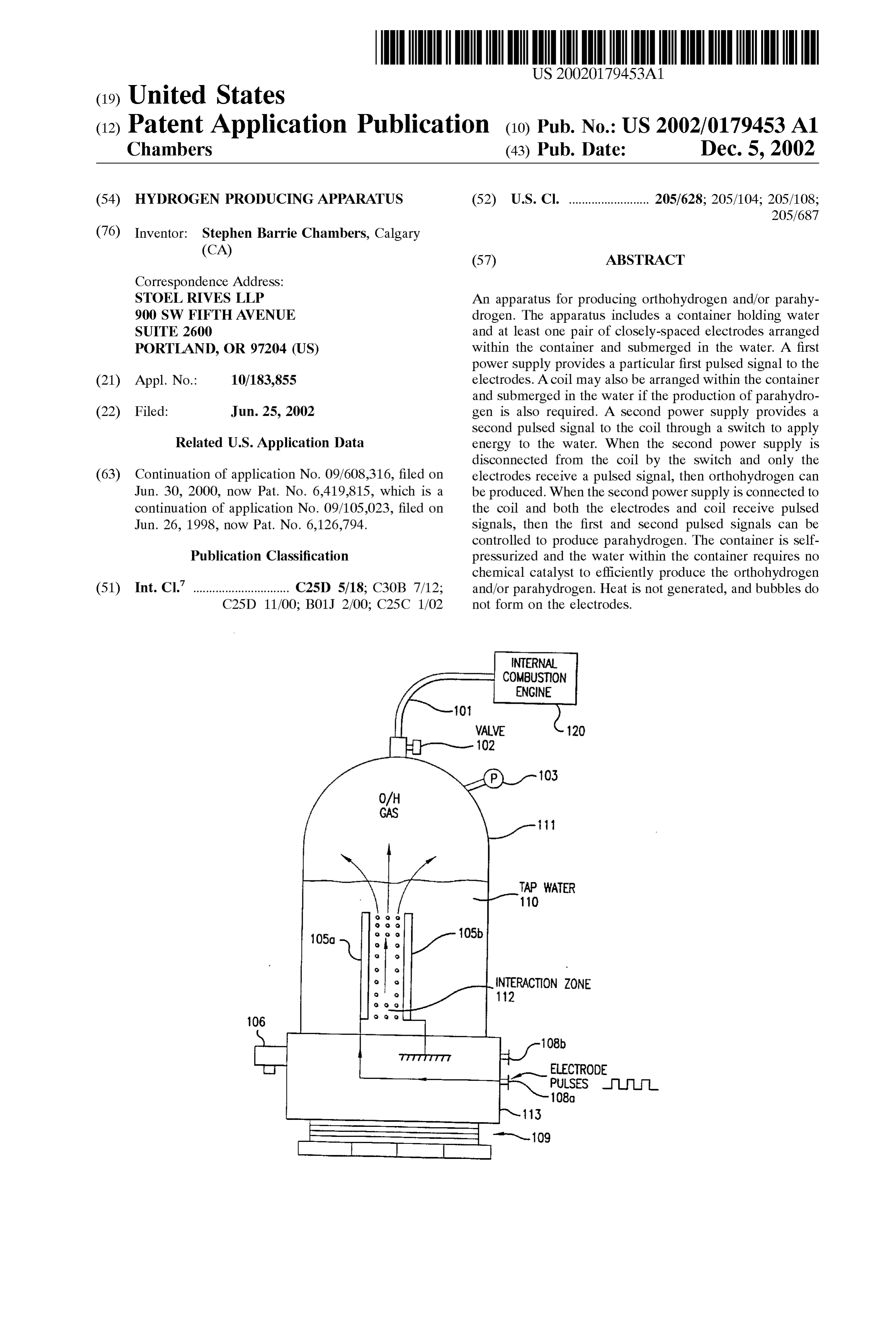
0020 FIG. 4a is a diagram illustrating a square wave Zone 112 therebetween. The electrodes 105a, 105b are pulsed signal which can be produced by the circuit of FIG. preferably made of the same material, Such as Stainless Steel. 5 and applied to the electrodes of FIGS. 1-3; 0033. In order to produce an optimal amount of hydrogen 0021 FIG. 4b is a diagram illustrating a saw tooth wave and oxygen, an equal spacing between the electrodes 105a, pulsed signal which can be produced by the circuit of FIG. 105b must be maintained. Moreover, it is preferable to 5 and applied to the electrodes of FIGS. 1-3; minimize the spacing between the electrodes 105a, 105b. However, the spacing between the electrodes 105a, 105 0022 FIG. 4c is a diagram illustrating a triangular wave cannot be positioned excessively close because arcing pulsed signal which can be produced by the circuit of FIG. between the electrodes 105a, 105b would occur. It has been 5 and applied to the electrodes of FIGS. 1-3; determined that a spacing of 1 mm is optimal spacing for 0023 FIG. 5 is an electronic circuit diagram illustrating producing hydrogen and oxygen. Spacing up to 5 mm can a power Supply which is connected to the electrodes of work effectively, but spacing above 5 mm has not worked FIGS. 1-3; well, except with excessive power. 0024 FIG. 6 is a side view of a cell for producing at least 0034) Hydrogen and oxygen gas outputted through out parahydrogen including a coil and a pair of electrodes put tube 101 can be transmitted by tube 101 to a device 120 according to a fourth embodiment of the present invention; using those gases, for example an internal combustion engine, Such as shown in FIG. 1. Instead of an internal 0.025 FIG. 7 is a side view of a cell for producing at least combustion engine, device 120 may be any device using parahydrogen including a coil and two pairs of electrodes hydrogen and OXygen, including a reciprocating piston according to a fifth embodiment of the present invention; engine, a gas turbine engine, a Stove, a heater, a furnace, a distillation unit, a water purification unit, a hydrogen/oxygen 0.026 FIG. 8 is a side view of a cell for producing at least jet, or other device using the gases. With an adequately parahydrogen including a coil and a pair of cylindrical productive example of the present invention, any Such shaped electrodes according to a Sixth embodiment of the device 120 using the output gases can be run continuously present invention; and without the need for Storing dangerous hydrogen and oxygen 0.027 FIG. 9 is as electronic circuit diagram illustrating gaSeS.
a power Supply which is connected to the coil and electrodes 0035 FIG. 2 shows a second embodiment of the present of FIGS. 6-8. invention which includes more than one pair of electrodes 205a-d. The spacing between the electrodes is less than 5
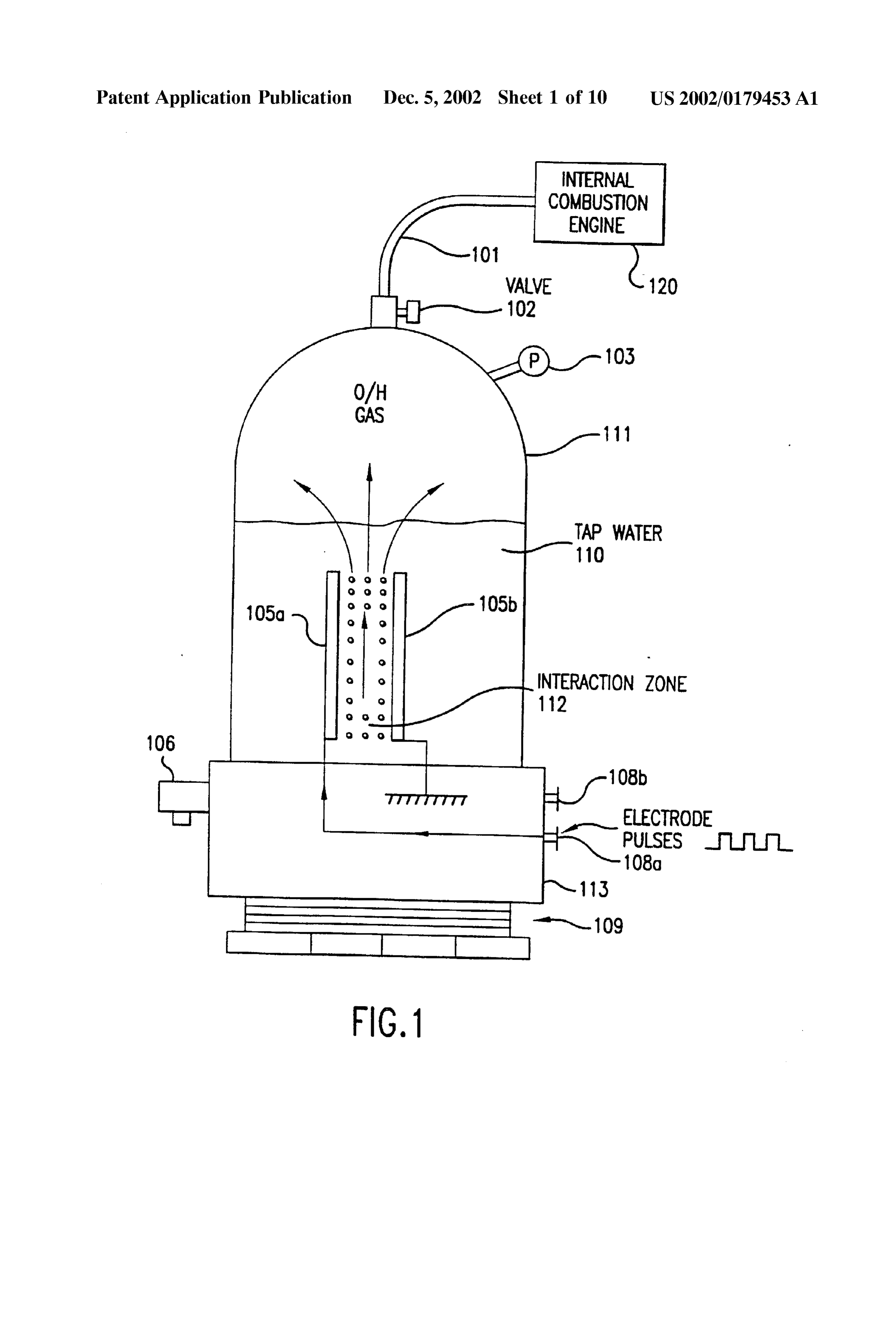
DETAILED DESCRIPTION OF PREFERRED mm as in the embodiment of FIG. 1. While FIG. 2 shows EMBODIMENT only one additional pair of electrodes, it is possible to include many more pairs (e.g., as many as 40 pairs of 0028 FIG. 1 shows a first embodiment of the present electrodes) within the cell. The rest of the cell illustrated in invention including a cell for producing hydrogen and FIG. 2 remains the same as that illustrated in FIG. 1. The oxygen. AS will be discussed below in conjunction with multiple electrodes are preferably flat plates closely spaced, FIGS. 6-8, the production of parahydrogen requires an parallel to each other.
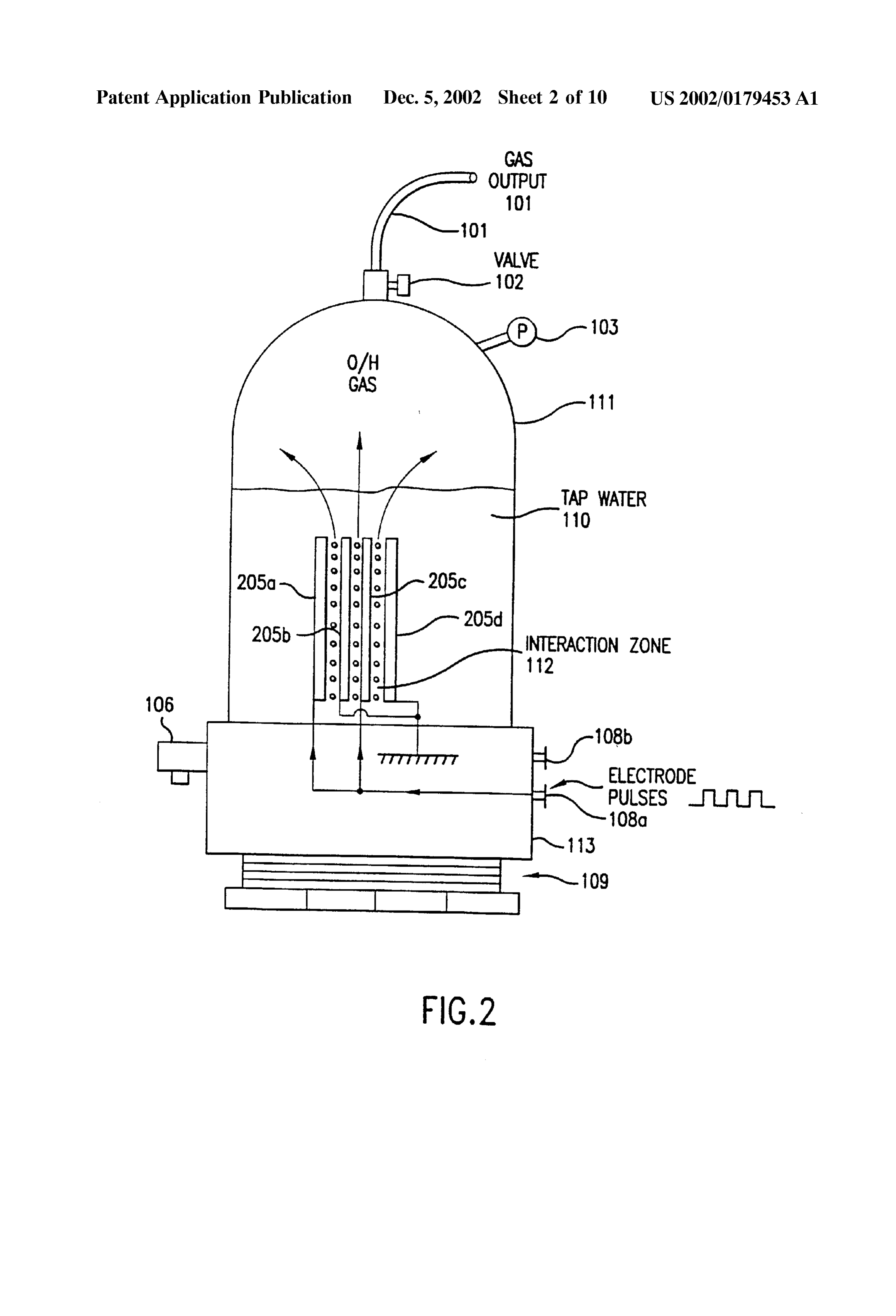
additional coil not shown in FIG. 1. Thus, the hydrogen produced by the first embodiment of FIG. 1 is orthohydro 0036 FIG. 3 illustrates a cell having a cylindrically gen. shaped electrodes 305a, 305b. The outer electrode 305b surrounds the coaxially aligned inner electrode 305a. The 0029. The cell includes a closed container 111 which is equal spacing of the electrodes 305a, 305b is less than 5 mm closed at its bottom portion by threaded plastic base 113 and and the interactive Zone is coaxially arranged between the Screw threadbase 109. The container 111 can be made of, for two electrodes 305a, 305b. While FIG. 3 illustrates the top example, plexiglass and have an exemplary height of 43 cm portion of the container 111 being formed by a plastic cap and an exemplary width of 9 cm. The container 111 holds tap 301, it will be appreciated to those skill in the art that the cap water 110 therein. 301 may be used in the embodiments of FIGS. 1-2 and the embodiment of FIG. 3 can utilize the same container 111 0030 The cell further includes a pressure gauge 103 to illustrated in FIGS. 1-2. As suggested by FIG. 3, the measure the pressure within the container 111. An outlet electrodes can be almost any shape Such as flat plates, rods, valve 102 is connected to the top of the container 111 to tubes or coaxial cylinders.
permit any gas within the container 111 to escape into an output tube 101. 0037) The electrodes 105a, 105b of FIG. 1 (or electrodes 205a-d of FIG. 2 or electrodes 305a, 305b of FIG. 3) are 0031. The cell also includes a pop valve 106 connected to respectively connected to power Supply terminals 108a, a base 113. The pop valve 106 provides a safety function by 108b so that they can receive a pulsed electrical signal from automatically releasing the pressure within the container 111 a power Supply. The pulsed Signal can be almost any if the pressure exceeds a predetermined threshold. For waveform and have a variable current level, Voltage level, example, the pop valve 106 may be set so that it will open frequency and mark-space ratio (i.e., a ratio of the duration if the pressure in the container exceeds 75 p.S.i. Since the of a single pulse to the interval between two Successive container 111 is built to withstand a pressure of about 200 pulses). For example, the power Supply providing power to p.s. i., the cell is provided with a large Safety margin. the electrodes can be a mains 110 volts to a 12 volt supply 0032) A pair of electrodes 105a, 105b are arranged within or a car battery.
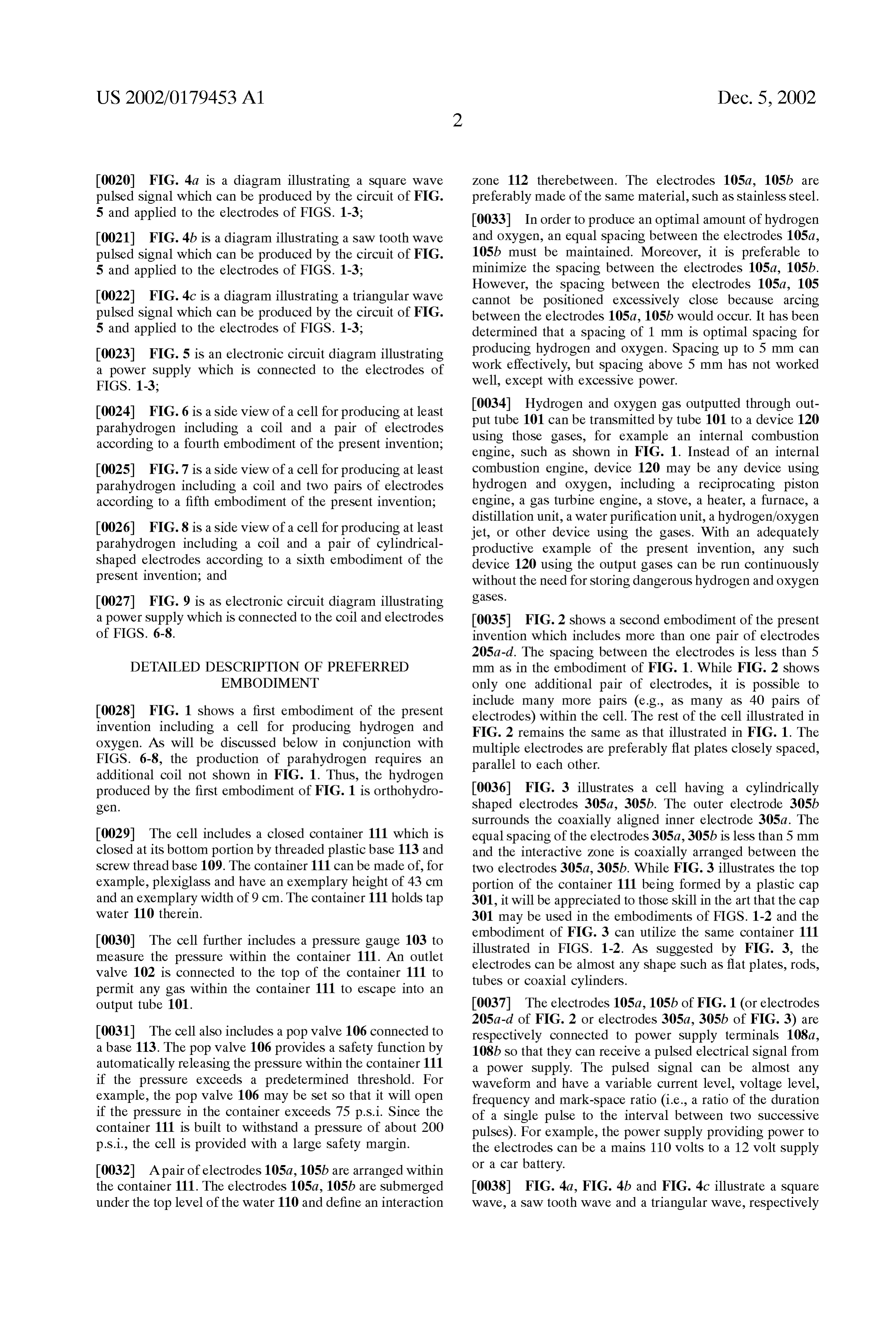
the container 111. The electrodes 105a, 105b are submerged 0038 FIG. 4a, FIG. 4b and FIG. 4c illustrate a square under the top level of the water 110 and define an interaction wave, a Saw tooth wave and a triangular wave, respectively
Page 14
US 2002/0179453 A1 Dec. 5, 2002
which can be applied to the electrodes 105a, 105b (or 0046) The power supply illustrated in FIG. 5 includes the 205a-d or 305a, 305b) in accordance with the present following parts and their exemplary components or values: invention. Each of the waveforms illustrated in FIGS. 4a-4c has a 1:1 mark-space ratio. As shown in FIG. 4b, the saw tooth wave will only reach a peak voltage at the end of the pulse duration. As shown in FIG. 4c, the triangular wave has Astable circuit NE555 or equivalent logic circuit a low peak voltage. It has been found that optimal results for Resistor R2 1OK producing hydrogen and oxygen in the present invention are Resistor R3 1OK obtained using a Square wave. Resistor R4 1OK
0039. After initiation of the pulsed signal from the power Resistor R6
Transistor TR1
supply, the electrodes 105a, 105b continuously and almost Transistor TR2 2N3904 instantaneously generate hydrogen and oxygen bubbles Transistor TR3 2N3055 or any high speed, high current silicon from the water 110 in the interaction Zone 112. Moreover, switch the bubbles can be generated with only minimal heating of Diode D2 1N4OO7 the water 110 or any other part of the cell. These bubbles rise Capacitors (not shown) Vcc by-pass capacitors as required. through the water 110 and collect in the upper portion of the container 111.
0047 The astable circuit is connected to the base of 0040. The generated bubbles are not bunched around or transistor TR1 through resistor R2. The collector of transis on the electrodes IO5a, 105b and thus readily float to the tor TR1 is connected to Voltage Supply Vcc through resistor Surface of the water 110. Therefore, there is no need to add R5 and the base of transistor TR2 through resistor R3. The a chemical catalyst to assist the conduction of the Solution or collector of transistor TR2 is connected to Voltage Supply reduce the bubble bunching around or on the electrodes Vcc through resistor R6 and the base of transistor TR3 105a, 105b. Thus, only tap water is needed for generation of through resistor R4. The collector of transistor TR3 is the hydrogen and oxygen in the present invention. connect to one of the electrodes of the cell and diode D2. 0041. The gases produced within the container are self The emitters of transistors TR1, TR2, TR3 are connected to pressurizing (i.e., pressure builds in the container by the ground. Resistors R5 and R6 serve as collector loads for production of gas, without an air pump). Thus, no additional transistors TR1 and TR2, respectively. The cell serves as the pump is needed to be coupled to the container 111 and the collector load for transistor TR3. Resistors R2, R3 and R4 produced gases do no need to be transported into a pressur serve to respectively ensure that transistors TR1, TR2 and ized container. TR3 are saturated. The diode D2 protects the rest of the circuit from any induced back emf within the cell.
0042. The power supply in the present invention is required to provide a pulsed signal having only 12 volts at 0048. The astable circuit is used to generate a pulse train 300 ma (3.6 watts). It has been found that an optimal amount at a Specific time and with a specific mark-space ratio. This of hydrogen and oxygen has been produced when the pulsed pulse train is provided to the base of transistor TR1 through Signal has mark-space ratio of 10:1 and a frequency of resistor R2. Transistor TR1 operates as an invert Switch. 10-250 KHZ. Using these parameters, the prototype cell of Thus, when the astable circuit produces an output pulse, the the present invention is capable of producing gas at the rate base Voltage of the transistor TR1 goes high (i.e., close to of 1 p.S. i. per minute. Accordingly, the cell of the present Vcc or logic 1). Hence, the voltage level of the collector of invention is capable of producing hydrogen and oxygen in a transistor TR1 goes low (i.e., close to ground or logic 0). highly efficient manner, quickly and with low power require 0049 Transistor TR2 also operates as an inverter. When mentS.
the collector voltage of transistor TR1 goes low, the base 0043. As noted above, the hydrogen produced by the voltage of transistor TR2 also goes low and transistor TR2 embodiments of FIGS. 1-3 is orthohydrogen. As is well turns off. Hence, the collector voltage of transistor TR2 and understood by those skilled in the art, orthohydrogen is the base voltage of Transistor TR3 go high. Therefore, the highly combustible. Therefore, any orthohydrogen produced transistor TR3 turns on in accordance with the mark-space can be transported from the container 11 through valve 102 ratio set forth by the astable circuit. When the transistor TR3 and outlet tube 101 to be used by a device such as an internal is on, one electrode of the cell is connected to Vcc and the combustion engine. other is connected to ground through transistor TR3. Thus, 0044) The present invention, with sufficient electrodes, the transistor TR3 can be turned on (and off) and therefore can generate hydrogen and oxygen fast enough to feed the the transistor TR3 effectively serves as a power Switch for the electrodes of the cell.
gases directly into an internal combustion engine or turbine engine, and run the engine continuously without accumula 0050 FIGS. 6-8 illustrate additional embodiments of the tion and Storage of the gases. Hence, this provides for the cell which are similar to the embodiments of FIGS. 1-3, first time a hydrogen/oxygen driven engine that is Safe respectively. However, each of embodiments of FIGS. 6-8 because it requires no Storage of hydrogen or oxygen gas. further includes a coil 104 arranged above the electrodes and 004.5 FIG. 5 illustrates an exemplary power supply for power supply terminals 107 connected to the coil 104. The providing D.C. pulsed signals Such as those illustrated in dimensions of the coil 104 can be, for example, 5x7 cm and FIGS. 4a-4c to the electrodes illustrated in FIGS. 1-3. AS have, for example, 1500 turns. The coil 104 is submerged under the Surface of the water 110.
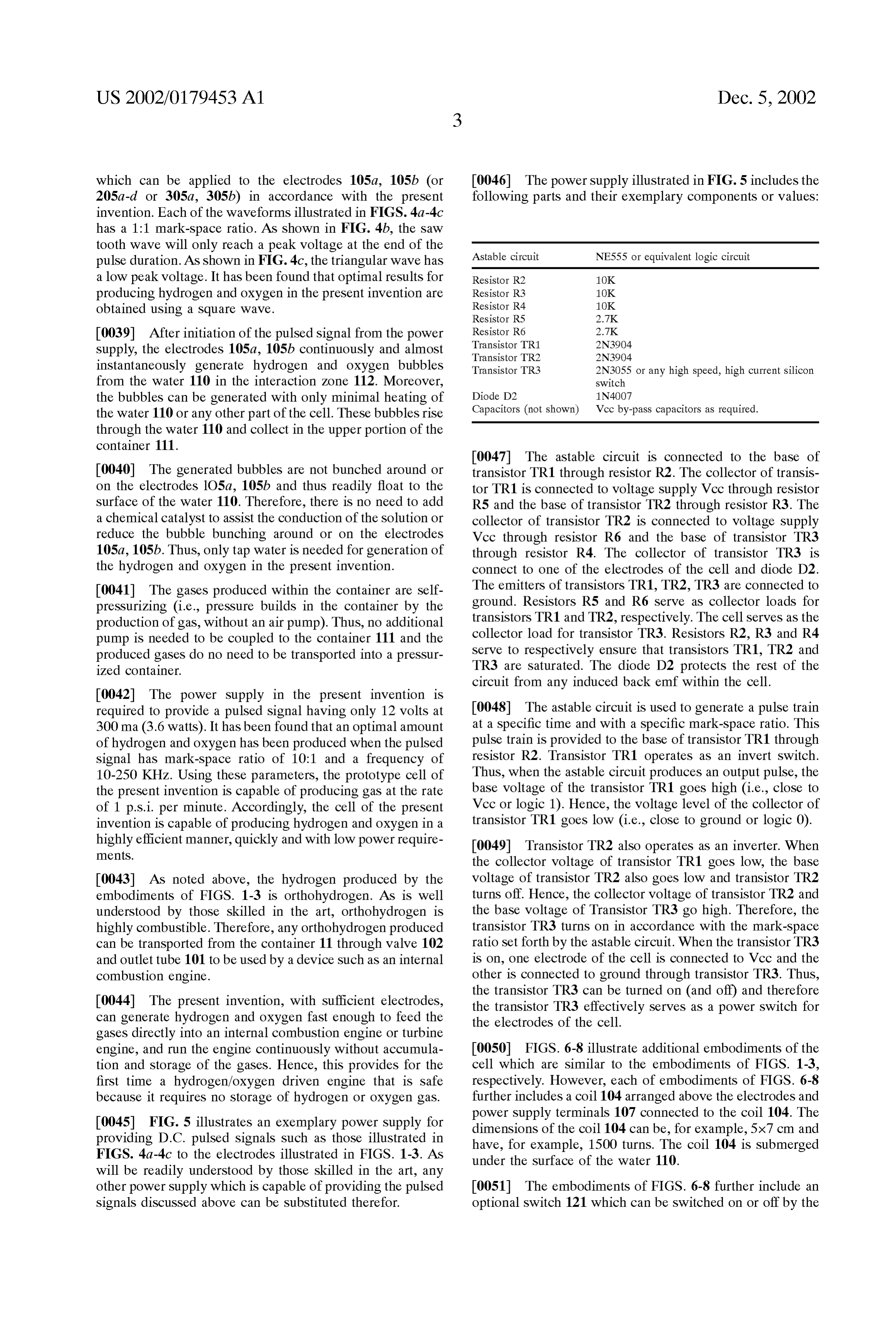
will be readily understood by those skilled in the art, any other power Supply which is capable of providing the pulsed 0051) The embodiments of FIGS. 6-8 further include an Signals discussed above can be Substituted therefor. optional Switch 121 which can be switched on or off by the
Page 15
US 2002/0179453 A1 Dec. 5, 2002
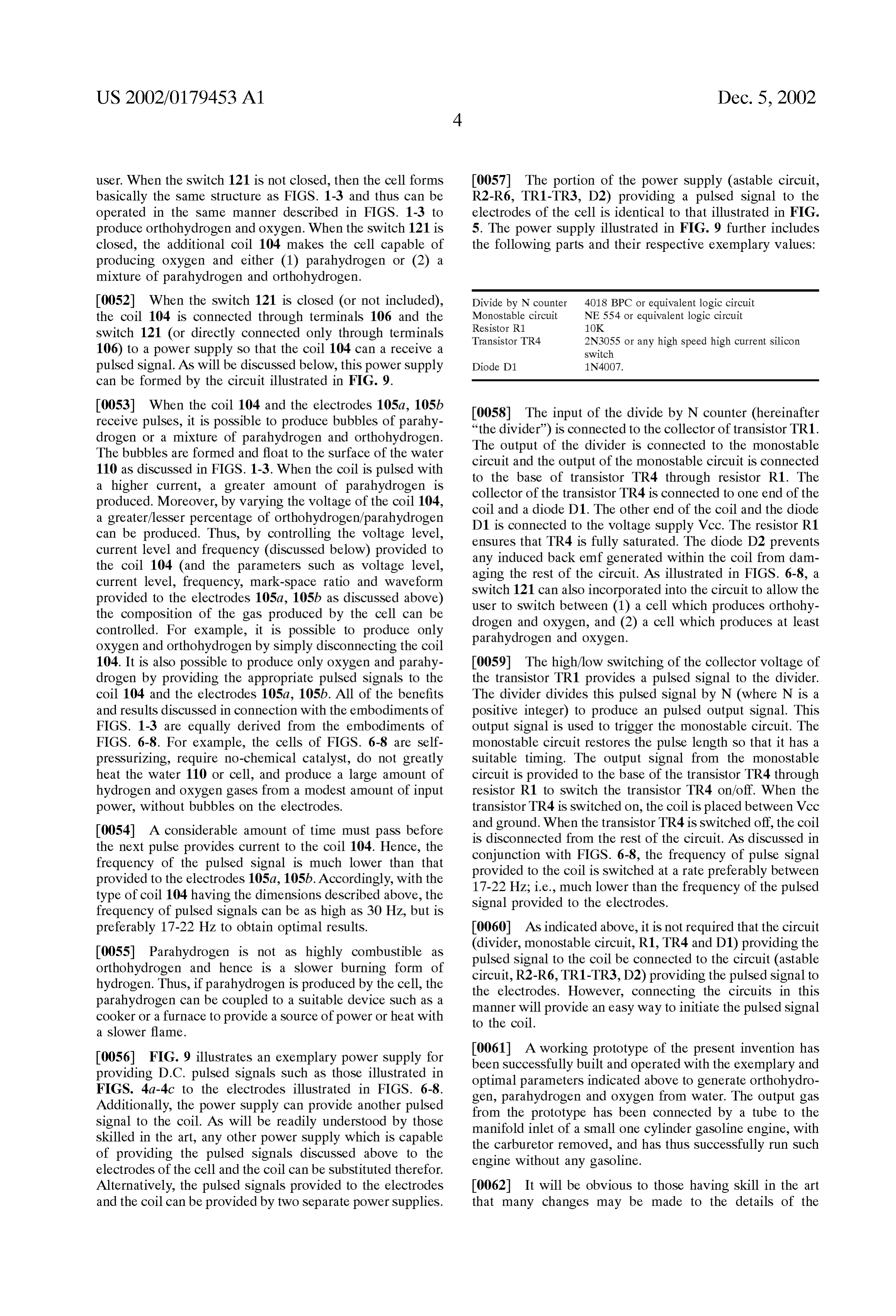
user. When the Switch 121 is not closed, then the cell forms 0057 The portion of the power supply (astable circuit, basically the same structure as FIGS. 1-3 and thus can be R2-R6, TR1-TR3, D2) providing a pulsed signal to the operated in the same manner described in FIGS. 1-3 to electrodes of the cell is identical to that illustrated in FIG. produce orthohydrogen and oxygen. When the Switch 121 is 5. The power Supply illustrated in FIG. 9 further includes closed, the additional coil 104 makes the cell capable of the following parts and their respective exemplary values: producing oxygen and either (1) parahydrogen or (2) a mixture of parahydrogen and orthohydrogen.
0052) When the switch 121 is closed (or not included), Divide by N counter 4018 BPC or equivalent logic circuit the coil 104 is connected through terminals 106 and the Monostable circuit NE 554 or equivalent logic circuit
Switch 121 (or directly connected only through terminals Transistor TR4 2N3055 or any high speed high current silicon 106) to a power supply so that the coil 104 can a receive a switch pulsed signal. AS will be discussed below, this power Supply Diode D1 1N4OO7.
can be formed by the circuit illustrated in FIG. 9.
0053) When the coil 104 and the electrodes 105a, 105b 0.058. The input of the divide by N counter (hereinafter receive pulses, it is possible to produce bubbles of parahy drogen or a mixture of parahydrogen and Orthohydrogen. “the divider”) is connected to the collector of transistor TR1. The bubbles are formed and float to the Surface of the water The output of the divider is connected to the monostable 110 as discussed in FIGS. 1-3. When the coil is pulsed with circuit and the output of the monostable circuit is connected a higher current, a greater amount of parahydrogen is to the base of transistor TR4 through resistor R1. The collector of the transistor TR4 is connected to one end of the produced. Moreover, by varying the voltage of the coil 104, coil and a diode D1. The other end of the coil and the diode a greater/lesser percentage of orthohydrogen/parahydrogen D1 is connected to the voltage supply Vcc. The resistor R1 can be produced. Thus, by controlling the Voltage level, ensures that TR4 is fully saturated. The diode D2 prevents current level and frequency (discussed below) provided to any induced back emf generated within the coil from dam the coil 104 (and the parameters Such as Voltage level, aging the rest of the circuit. As illustrated in FIGS. 6-8, a current level, frequency, mark-space ratio and waveform Switch 121 can also incorporated into the circuit to allow the provided to the electrodes 105a, 105b as discussed above) user to Switch between (1) a cell which produces orthohy the composition of the gas produced by the cell can be drogen and oxygen, and (2) a cell which produces at least controlled. For example, it is possible to produce only parahydrogen and OXygen.
oxygen and Orthohydrogen by Simply disconnecting the coil 104. It is also possible to produce only oxygen and parahy 0059) The high/low switching of the collector voltage of drogen by providing the appropriate pulsed signals to the the transistor TR1 provides a pulsed signal to the divider. coil 104 and the electrodes 105a, 105b. All of the benefits The divider divides this pulsed signal by N (where N is a and results discussed in connection with the embodiments of positive integer) to produce an pulsed output signal. This FIGS. 1-3 are equally derived from the embodiments of output signal is used to trigger the monostable circuit. The FIGS. 6-8. For example, the cells of FIGS. 6-8 are self monostable circuit restores the pulse length So that it has a preSSurizing, require no-chemical catalyst, do not greatly Suitable timing. The output signal from the monostable heat the water 110 or cell, and produce a large amount of circuit is provided to the base of the transistor TR4 through hydrogen and oxygen gases from a modest amount of input resistor R1 to Switch the transistor TR4 on/off. When the power, without bubbles on the electrodes. transistor TR4 is Switched on, the coil is placed between Vcc 0054. A considerable amount of time must pass before and ground. When the transistor TR4 is switched off, the coil is disconnected from the rest of the circuit. AS discussed in the next pulse provides current to the coil 104. Hence, the conjunction with FIGS. 6-8, the frequency of pulse signal frequency of the pulsed signal is much lower than that provided to the coil is switched at a rate preferably between provided to the electrodes 105a, 105b. Accordingly, with the 17-22 Hz; i.e., much lower than the frequency of the pulsed type of coil 104 having the dimensions described above, the Signal provided to the electrodes. frequency of pulsed signals can be as high as 30 Hz, but is preferably 17-22 Hz to obtain optimal results. 0060 AS indicated above, it is not required that the circuit 0.055 Parahydrogen is not as highly combustible as (divider, monostable circuit, R1, TR4 and D1) providing the orthohydrogen and hence is a slower burning form of pulsed signal to the coil be connected to the circuit (astable hydrogen. Thus, if parahydrogen is produced by the cell, the circuit, R2-R6, TR1-TR3, D2) providing the pulsed signal to parahydrogen can be coupled to a Suitable device Such as a the electrodes. However, connecting the circuits in this cooker or a furnace to provide a Source of power or heat with manner will provide an easy way to initiate the pulsed signal to the coil.
a slower flame.
0056 FIG. 9 illustrates an exemplary power supply for 0061. A working prototype of the present invention has providing D.C. pulsed signals Such as those illustrated in been Successfully built and operated with the exemplary and FIGS. 4a-4C to the electrodes illustrated in FIGS. 6-8.
optimal parameters indicated above to generate orthohydro
Additionally, the power Supply can provide another pulsed gen, parahydrogen and oxygen from water. The output gas signal to the coil. As will be readily understood by those from the prototype has been connected by a tube to the skilled in the art, any other power Supply which is capable manifold inlet of a Small one cylinder gasoline engine, with of providing the pulsed signals discussed above to the the carburetor removed, and has thus Successfully run Such electrodes of the cell and the coil can be substituted therefor.
engine without any gasoline.
Alternatively, the pulsed signals provided to the electrodes 0062. It will be obvious to those having skill in the art and the coil can be provided by two Separate power Supplies. that many changes may be made to the details of the
Page 16
US 2002/0179453 A1 Dec. 5, 2002
above-described embodiment of this invention without 7. The method of claim 1 in which the pulsed electrical departing from the underlying principles thereof. The Scope Signal is a variable Voltage pulsed electrical Signal. of the present invention should, therefore, be determined 8. The method of claim 1 in which the pulsed electrical only by the following claims. Signal is a Square Wave.
1. A method, comprising: 9. The method of claim 1 in which the pulsed electrical Signal is a Sawtooth wave.
providing a container; 10. The method of claim 1 in which the pulsed electrical filling the container with a fluid including water until the Signal is a triangular wave.
container is at least partly filled; 11. A method of producing hydrogen, comprising: Submersing a pair of electrodes in the fluid; providing a container;
positioning Said electrodes So that they are Spaced apart 5 filling the container with a fluid including water until the mm or less, and container is at least partly filled; after Submersing and positioning Said electrodes, applying Submersing a pair of electrodes in the fluid; a pulsed electrical signal to one of Said electrodes, the pulsed electrical Signal having a frequency from 10 to spacing Said electrodes apart 5 mm or less to thereby form 250 kHz, thereby producing hydrogen. an interaction Zone between Said electrodes, and 2. The method of claim 1 adapted to produce hydrogen in after Submersing and Spacing Said electrodes, applying a the absence of a chemical catalyst. pulsed electrical Signal to one of Said electrodes, 3. The method of claim 1 adapted to produce hydrogen in thereby producing hydrogen and oxygen in the inter the absence of potassium hydroxide and Sodium hydroxide. action Zone.
4. The method of claim 1 in which the pulsed electrical 12. The method of claim 11 adapted to produce hydrogen Signal has a mark-space ratio from 1:1 to 10:1. in the absence of a chemical catalyst. 5. The method of claim 1, further comprising: 13. The method of claim 11 adapted to produce hydrogen providing a device having an input port connected to the in the absence of potassium hydroxide and Sodium hydrox output port of the container, the device Selected from ide.
the group consisting of: 14. The method of claim 11 in which the pulsed electrical a. an internal combustion engine; Signal has a mark-space ratio from 1:1 to 10:1. 15. The method of claim 11 in which the pulsed electrical b. a reciprocating piston engine; signal has a frequency of from 10 to 250 kHz. c. a gas turbine engine; 16. The method of claim 11, further comprising: d. a Stove; arranging a coil within the container, and e. a heater; applying a Second pulsed electrical Signal to the coil. f. a furnace, 17. The method of claim 11 in which the pulsed electrical g. a distillation unit; Signal is a variable Voltage pulsed electrical Signal. 18. The method of claim 11 in which the pulsed electrical h. a water purification unit; and Signal is a Square Wave.
i. a hydrogen/oxygen flame jet; and 19. The method of claim 11 in which the pulsed electrical operating the device. Signal is a Sawtooth wave.
6. The method of claim 1, further comprising: 20. The method of claim 11 in which the pulsed electrical Signal is a triangular wave.
arranging a coil within the container; and applying a Second pulsed electrical Signal to the coil. k k k k k
Provenance
- Collection
- Patents citing this work
- Current assignee
- Xogen Technologies Inc
- Original assignee
- Xogen Power Inc
- Pages
- 16
- Method
- pdftotext (the PDF's own text layer) + pdftoppm 300dpi page scans
- Patent office record
- patents.google.com →
- Source
- Google Patents citing-documents table
- Inventors
- Stephen Chambers; Xogen Power Inc
- Published
- 2002-12-05
- Transcribed from
- patentimages.storage.googleapis.com →