(A3)
Voltage Intensifier Circuit
Where it is first named
The liberated and traveling Fuel-Gases enters into ans passed through a patented Fuel-Gas Processor (E) that performs and functions as a Gas Ionization Chamber when another Voltage Intensifier Circuit (A3) is activated by Gas Acceleration Control Unit (B/F), as illustrated in Figure 2 as to Figure 7
How it is written
- (A3) 2×
Drawings 3
-
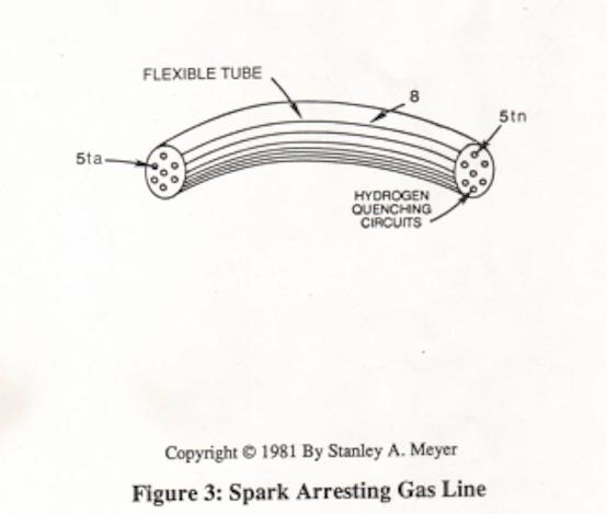
Voltage Intensifier Circuit (A3) is interlocked with Safety Control Circuit (D) through Electronic Control Unit (B). · Fuel-Gases / Quenching Tube
-
Carries this number · Fuel-Gases / Quenching Tube
-
The Fuel-Cell is composed of Resonant Cavities pre-arranged to maximize Fuel-Energy delivery to the car engine, as illustrated in Figure 2 as to Figure 4. · WFC - Resonant Cavity Assembly
Where it is named · 2
Fuel-Gases / Quenching Tube 2×
-
Voltage Intensifier Circuit (A3)
The liberated and traveling Fuel-Gases enters into ans passed through a patented Fuel-Gas Processor (E) that performs and functions as a Gas Ionization Chamber when another Voltage Intensifier Circuit (A3) is activated by Gas Acceleration Control Unit (B/F), as illustrated in Figure 2 as to Figure 7
-
Voltage Intensifier Circuit (A3)
Voltage Intensifier Circuit (A3) is interlocked with Safety Control Circuit (D) through Electronic Control Unit (B).