patent · US8985096B2
Heat exchanging structure including solar heat converter
24 March 2015
Page 1 — bibliographic record
(12) United States Patent (10) Patent No.: US 8,985,096 B2 Nakamura (45) Date of Patent: Mar. 24, 2015
(54) HEAT EXCHANGING STRUCTURE 38: A : : SE .......................... 33.
INCLUDING SOLAR HEAT CONVERTER 4.402,306 A * 9/1983 McElroy, Jr. ... 126.619 4,407.268 A * 10/1983 Jardin ......... ... 126,618 (75) Inventor: Katsushige Nakamura, Chofu (JP) 4,452,232 A * 6/1984 E. ............... ... 126/587 4,479,485 A * 10/1984 McDougal et al. ... 126/648 (73) Assignee: Mitaka Kohki Co., Ltd., Tokyo (JP) 4,546,758 A * 10/1985 Ebernard ... ... 126,635 4,619,244. A * 10/1986 Marks ........ ... 126,680
(*) Notice: Subject to any disclaimer, the term of this 36. A : 123; Gibson et al. 1. patent is extended or adjusted under 35 w- W cur
U.S.C. 154(b) by 992 days. (Continued) (21) Appl. No.: 13/010,911 FOREIGN PATENT DOCUMENTS 1-1. CN 201425380 3, 2010 (22) Filed: Jan. 21, 2011 CN 1019.24497 12/2010 (65) Prior Publication Data (Continued) US 2011/0114082 A1 May 19, 2011 OTHER PUBLICATIONS (51) Int. Cl China Office action, mail date is Dec. 25, 2013. F24, 2/30 (2006.01) Primary Examiner — Steven B McAllister fit, 5T R Assistant Examiner — Nikhil Mashruwala F24, 2/8 3:08: (74) Attorney, Agent, or Firm — Greenblum & Bernstein,
CPC. F24J
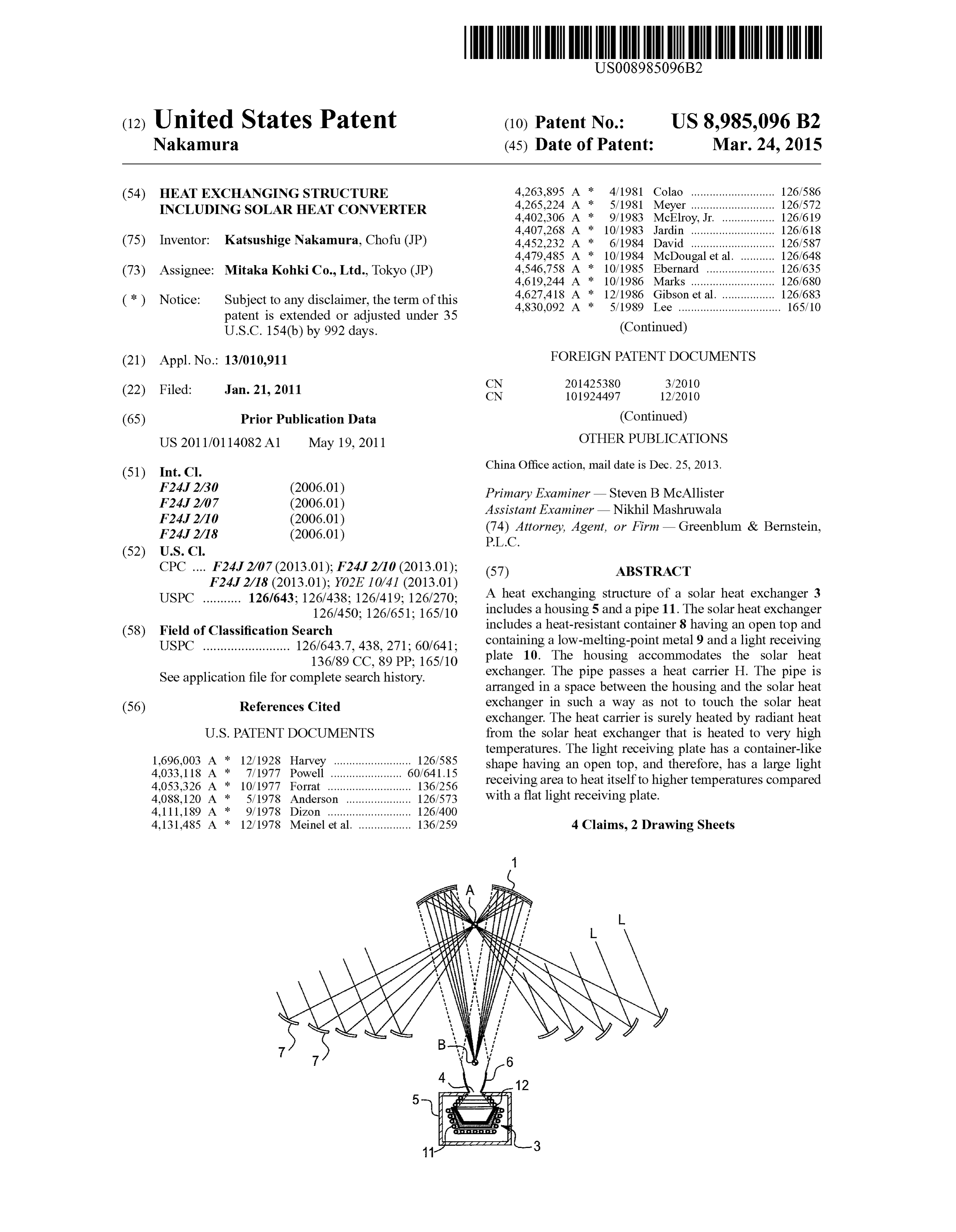
USPC ........... 126/643; 126/438: 126/419, 126/270. A heat exchanging structure of a solarSO3heat Caiexchanger 3 126/450; 126/651; 165/10 ludes a housing 5 and a pipe 11. The Solar heat exchang
includes a heat-resistant container 8 having an open top and (58) Field of Classification Search 9. p p USPC ......................... 126,643.7,438,271, 60.641, containing a low-melting-point metal 9 and a light receiving 136789 CC 89 PP 165/10 plate 10. The housing accommodates the Solar heat
See appl1cauon
let searcn s exchanger. The pipe passes a heat carrier H. The pipe is
Ille Ior complete n1Story arranged in a space between the housing and the Solar heat (56) References Cited exchanger in Such a way as not to touch the Solar heat exchanger. The heat carrier is Surely heated by radiant heat
temperatures. The light receiving plate has a container-like 1,696,003 A * 12/1928 Harvey ......................... 126,585 shape having an open top, and therefore, has a large light 4,033,118 A * 7, 1977 Powell ... ... 60,641.15 receiving area to heat itself to higher temperatures compared 4,053,326 A * 10/1977 Forrat ........................... 136,256 gar 9. p p 4,088,120 A * 5/1978 Anderson ..................... 26/573 with a flat light receiving plate. 4,111,189 A * 9/1978 Dizon ........................... 126,400 4,131.485 A * 12/1978 Meinel et al. ................. 136,259 4 Claims, 2 Drawing Sheets
Page 2
Drawing sheet — no readable text.

Page 3
Drawing sheet — no readable text.
Page 4
Drawing sheet — no readable text.
Page 5
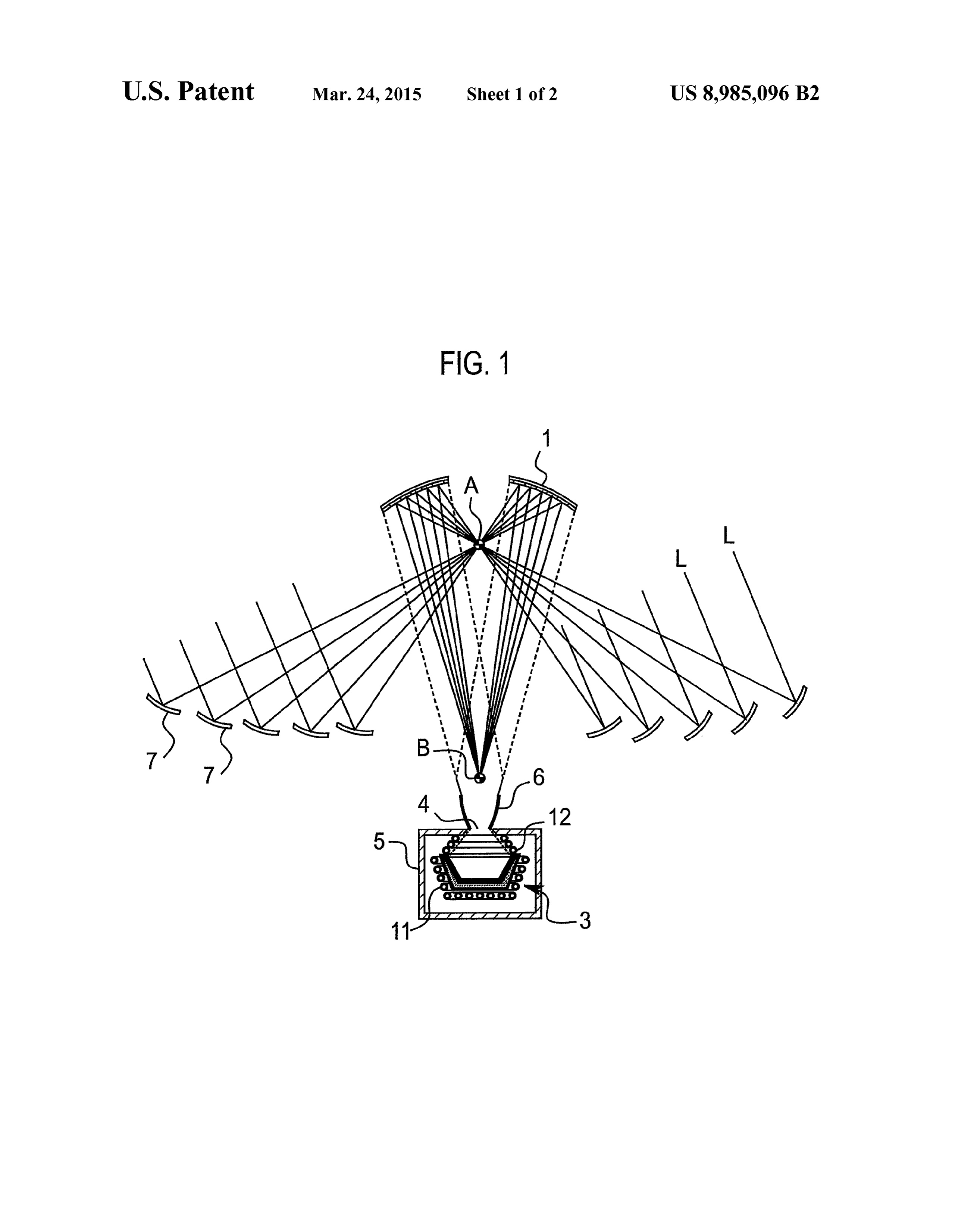
HEAT EXCHANGING STRUCTURE mirror surface of the elliptical mirror 1 is part of a spheroid. INCLUDING SOLAR HEAT CONVERTER Below the spheroid in a long axis direction, a first focus A and a second focus B that are confocal are present. Arranged
BACKGROUND OF THE INVENTION under the elliptical mirror 1 is a Solar heat exchanger 3 (i.e., a Solar heat converter) that converts Solar rays L into thermal 1. Field of the Invention energy. The Solar heat exchanger 3 is accommodated in a The present invention relates to a heat exchanging structure housing 5 that has a top opening 4 and is made of ALC of a Solar heat exchanger. (autoclaved lightweight concrete). The opening 4 of the hous 2. Description of Related Art ing 5 is provided with a collector mirror 6 having a tapered A Solar concentration apparatus used with a solar heat 10 cylindrical shape. An inner face of the housing 5 may be exchanger is disclosed in, for example, Japanese Unexamined coated with a reflective film to reflect outward thermal radia Patent Application Publication No. H11-119105. This related tion.
art is a beam-down solar concentration apparatus that On the ground around the Solar heat exchanger 3, many employs primary mirrors called heliostats. The heliostats 15 heliostats 7 serving as primary mirrors are arranged to Sur reflect solar rays toward a secondary mirror installed at the round the elliptical mirror 1. Each of the heliostats 7 is con top of a tower. The secondary mirror downwardly reflects the trolled
Solar rays so that the reflected Solar rays are concentrated at a beam Lbyreflected a solar ray sensor (not illustrated) so that a solar by the heliostat 7 may pass through the first point on the ground.
According to this related art, the downwardly reflected passed through the beams focus A. The solar first
L reflected by the heliostats 7 and focus A are downwardly reflected by
Solar rays strike a light receiving plate on the ground, to heat the light receiving plate to 1000 degrees centigrade or higher. the elliptical mirror 1, are collected at the second focus B, are gathered by the collector mirror 6, and are received by the
SUMMARY OF THE INVENTION Solar heat exchanger 3.
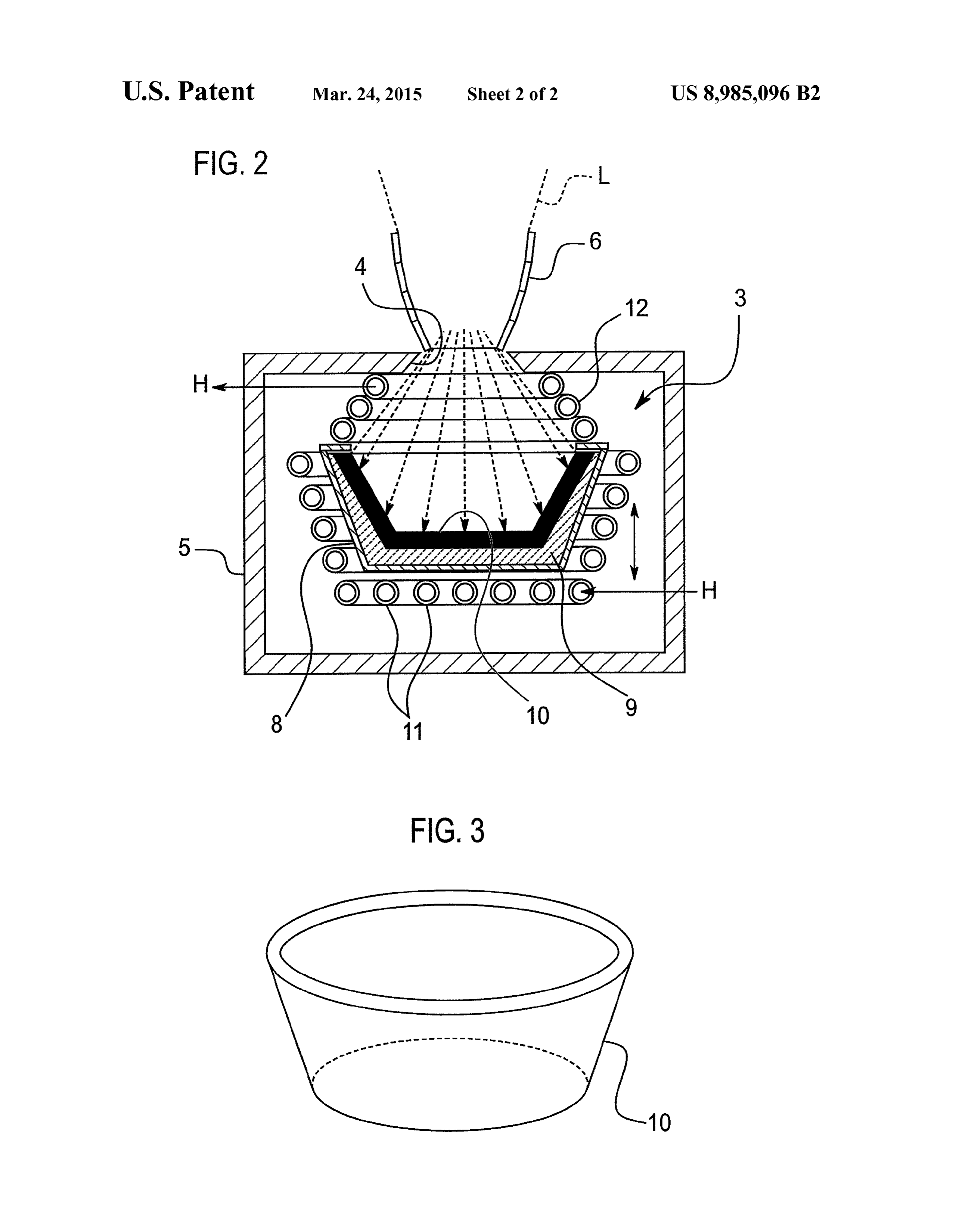
Inside the housing 5, a heat-resistant container 8 of heat
The related art mentioned above directly heats the light 25 resistant metal is arranged with a space interposed between receiving plate with Solar rays to very high temperatures. If the housing 5 and the container 8. The container 8 has an open the high-temperature heat is effectively extracted through top and a tapered side wall that widens from a circular bottom heat exchange from the light receiving plate, the heat will toward the open top.
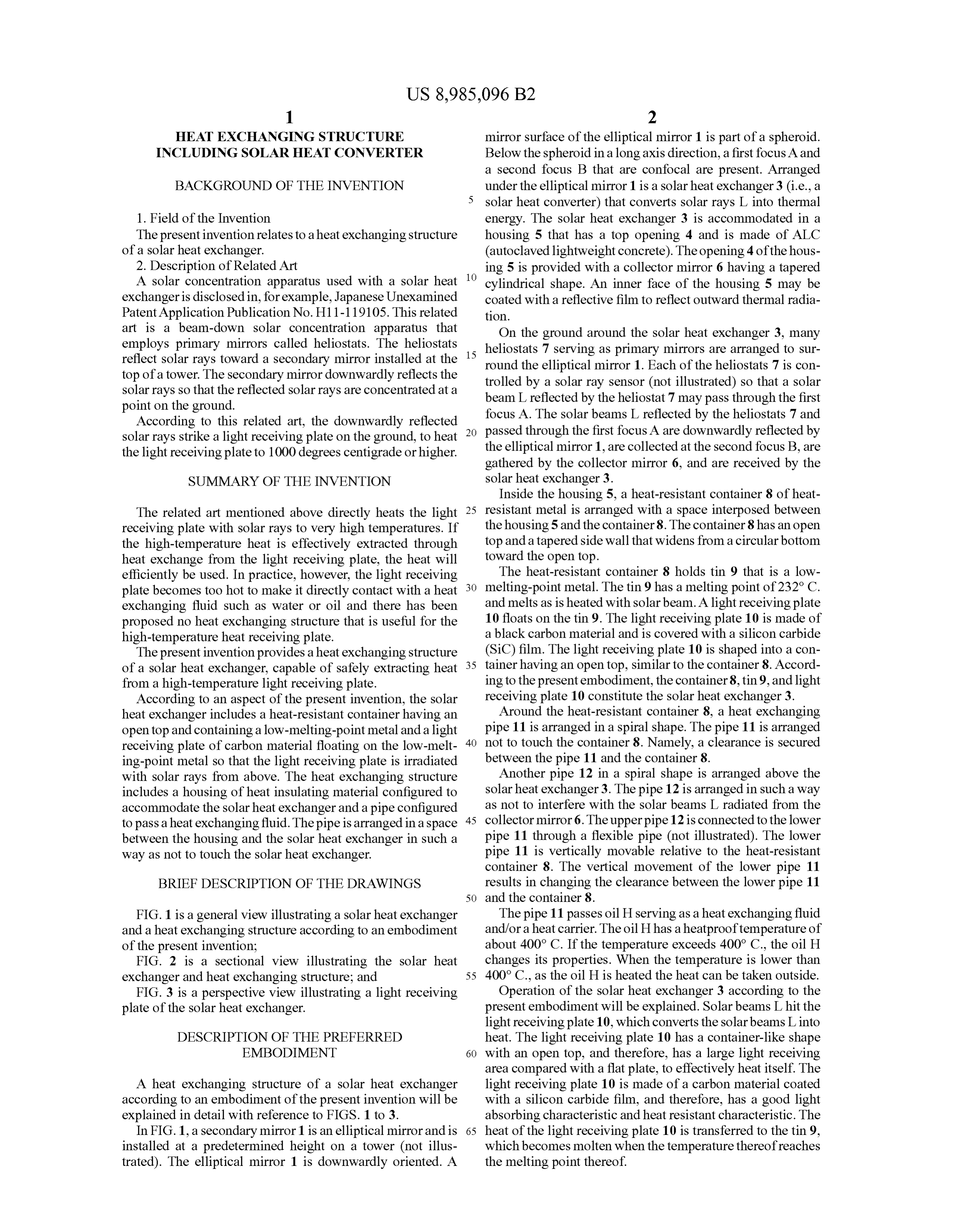
efficiently be used. In practice, however, the light receiving The heat-resistant container 8 holds tin 9 that is a low plate becomes too hot to make it directly contact with a heat 30 melting-point metal. The tin 9 has a melting point of 232° C. exchanging fluid Such as water or oil and there has been and melts as is heated with Solar beam. A light receiving plate proposed no heat exchanging structure that is useful for the 10 floats on the tin 9. The light receiving plate 10 is made of high-temperature heat receiving plate. a black carbon material and is covered with a silicon carbide The present invention provides aheat exchanging structure (SiC) film. The light receiving plate 10 is shaped into a con of a Solar heat exchanger, capable of safely extracting heat 35 tainer having an open top, similar to the container 8. Accord from a high-temperature light receiving plate. ing to the present embodiment, the container 8, tin9, and light According to an aspect of the present invention, the Solar receiving plate 10 constitute the solar heat exchanger 3. heat exchanger includes a heat-resistant container having an Around the heat-resistant container 8, a heat exchanging open top and containing a low-melting-point metal and a light pipe 11 is arranged in a spiral shape. The pipe 11 is arranged receiving plate of carbon material floating on the low-melt 40 not to touch the container 8. Namely, a clearance is secured ing-point metal so that the light receiving plate is irradiated between the pipe 11 and the container 8. with Solar rays from above. The heat exchanging structure Another pipe 12 in a spiral shape is arranged above the includes a housing of heat insulating material configured to Solar heat exchanger 3. The pipe 12 is arranged in Such a way accommodate the Solar heat exchanger and a pipe configured as not to interfere with the solar beams L radiated from the to pass aheat exchanging fluid. The pipe is arranged in a space 45 collector mirror 6. The upper pipe 12 is connected to the lower between the housing and the Solar heat exchanger in Such a pipe 11 through a flexible pipe (not illustrated). The lower way as not to touch the Solar heat exchanger. pipe 11 is vertically movable relative to the heat-resistant container 8. The vertical movement of the lower pipe 11
BRIEF DESCRIPTION OF THE DRAWINGS results in changing the clearance between the lower pipe 11 50 and the container 8.
FIG. 1 is a general view illustrating a Solar heat exchanger The pipe 11 passes oil H serving as a heat exchanging fluid and a heat exchanging structure according to an embodiment and/or a heat carrier. The oil H has a heatprooftemperature of of the present invention; about 400°C. If the temperature exceeds 400° C., the oil H FIG. 2 is a sectional view illustrating the solar heat changes its properties. When the temperature is lower than exchanger and heat exchanging structure; and 55 400°C., as the oil His heated the heat can be taken outside. FIG. 3 is a perspective view illustrating a light receiving Operation of the Solar heat exchanger 3 according to the plate of the Solar heat exchanger. present embodiment will be explained. Solar beams L hit the light receiving plate 10, which converts the solar beams Linto
DESCRIPTION OF THE PREFERRED heat. The light receiving plate 10 has a container-like shape EMBODIMENT 60 with an open top, and therefore, has a large light receiving area compared with a flat plate, to effectively heat itself. The
A heat exchanging structure of a Solar heat exchanger light receiving plate 10 is made of a carbon material coated according to an embodiment of the present invention will be with a silicon carbide film, and therefore, has a good light explained in detail with reference to FIGS. 1 to 3. absorbing characteristic and heat resistant characteristic. The In FIG. 1, a secondary mirror 1 is an elliptical mirror and is 65 heat of the light receiving plate 10 is transferred to the tin 9. installed at a predetermined height on a tower (not illus which becomes molten when the temperature thereofreaches trated). The elliptical mirror 1 is downwardly oriented. A the melting point thereof.
Page 6
The moltentin9 is present between the light receiving plate clearance between the pipe and the Solar heat exchanger 3 and 10 and the heat-resistant container 8 and is in contact with optimize the quantity of radiant heat acting on the pipe. both of them, to effectively transfer heat from the light receiv According to the present invention, the light receiving plate ing plate 10 to the container 8. Namely, the solar heat 10 is made of solid silicon carbide or a solid carbon material exchanger 3 including the light receiving plate 10, tin 9, and coated with a silicon carbide film, to realize a high solar beam container 8 is not only aheat source of very high temperature absorbing efficiency and heat resistance. but also a radiator to radiate heat around the same. Although the invention has been described above by refer The radiant heat from the container 8 is a main heat source ence to certain embodiments of the invention, the invention is for the oil H passing through the pipe 11 and heats the oil H not limited to the embodiments described above. Modifica through the pipes 11 and 12. Since the oil His heated with the 10 tions and variations of the embodiments described above will radiant heat, the temperature of the oil H does not excessively occur to those skilled in the art, in light of the teachings. The increase, and therefore, the properties of the oil H never scope of the invention is defined with reference to the follow deteriorate. ing claims.
The lower pipe 11, which is in the vicinity of the solar heat exchanger 3 and has a high heating efficiency due to the 15 What 1. A is claimed is:
heat exchanging structure, comprising:
radiant heat, is vertically movable to adjust the clearance between the pipe 11 and the heat-resistant container 8. This a solar heat converter having a heat-resistant container results in adjusting the quantity of radiant heat applied to the provided with an open top, wherein the heat-resistant pipe 11 and optimizing the temperature of oil H passing container contains a low-melting-point metal and a light through the pipe 11. receiving plate of carbon material floating on the low According to the present embodiment, the light receiving melting-point metal so that the light receiving plate is plate 10 is made of a black carbon material coated with a irradiated with solar rays from above: silicon carbide film. Instead, the light receiving plate 10 may a housing of heat insulating material that accommodates entirely be made of silicon carbide. According to the embodi the solar heat converter; and ment, the low-melting-point metal is tin. Instead, the low 25 a pipe configured to pass a heat carrier, the pipe being arranged in a spiral shape and in a space between the melting-point metal may be lead or solder.
As mentioned above, the present invention makes the pipe housing and the Solar heat converter, and the pipe Sur for passing a heat carrier not to touch the Solar heat exchanger rounding the heat-resistant container so as not to contact 3 including the light receiving plate 10, so that the heat carrier the Solar heat converter, the pipe having an adjustable in the pipe is heated with radiant heat from the solar heat 30 2. position relative to the heat-resistant container. The heat exchanging structure of claim 1, wherein the exchanger 3. This configuration secures safety. The tempera ture of the solar heat exchanger 3 becomes very high, and top. light receiving plate has a container-like shape having an open therefore, the radiant heat therefrom can surely heat the heat 3. The heat exchanging structure of claim 1, wherein the carrier in the pipe. pipe is configured to be movable vertically relative to the According to the present invention, the light receiving plate 35 heat-resistant container.
10 has a container-like shape having an open top, and there fore, has a large light receiving area to heat itself to higher light 4. The heat exchanging structure of claim 1, wherein the temperatures compared with a flat light receiving plate. receiving plate is made of solid silicon carbide or a solid According to the present invention, the pipe is vertically carbon material entirely coated with a silicon carbide film. movable relative to the solar heat exchanger 3, to adjust a k k k k k
Provenance
- Collection
- Patents citing this work
- Original assignee
- Mitaka Kohki Co Ltd
- Pages
- 6
- Method
- pdftotext (the PDF's own text layer) + pdftoppm 300dpi page scans
- Patent office record
- patents.google.com →
- Source
- Google Patents citing-documents table
- Inventors
- Katsushige Nakamura; Mitaka Kohki Co Ltd
- Published
- 2015-03-24
- Transcribed from
- patentimages.storage.googleapis.com →