patent · US4627418
Apparatus for the carbothermic reduction of metal oxides using solar energy
9 December 1986
Page 1 — bibliographic record
United States Patent (19) 11 Patent Number: 4,627,418 Gibson et al. (45) Date of Patent: Dec. 9, 1986 (54) APPARATUS FOR THE CARBOTHERMC 3,993,458 11/1976 Anitol, Jr. ............................. 48/209 REDUCTION OF METAL OXDES USING 4,000,733 1/1977 Pouly .................................. 126/451 SOLAR ENERGY 4,068,474 1/1978 Dimitroff. ... 126/440X (75) Inventors: James O. Gibson; Mark G. Gibson, 4,090,498 5/1978 Benson ................................ 26/442 4,114,685 9/1978 Schwartz .. ... 126/440 both of Pacific Palisades, Calif. 4,121,564 10/1978 Schwartz .. ... 126/438 (73) Assignee: Geruldine Gibson, Santa Monica, 4,135,489 1/1979 Jarvinen .... ... 126/901 4,139,286 2/1979 Hein et al. ... 126/440X
Calif.; a part interest 4,164,123 8/1979 Smith ........ ... 126/438 X (21) Appl. No.: 570,858 4,202,321 5/1980 Volna .................................. 126/425 4,204,914 5/1980 Diggs ... ... 126/439 22 Filed: Jan. 16, 1984 4,205,661 6/1980 Chapman . ... 126/425 4,229, 184 10/1980 Gregg ... ... 126/438
Related U.S. Application Data 4,249,515 2/1981 Page ...... ... 126/438 4,263,895 4/1981 Colao ........ ... 126/438 60 Division of Ser. No. 184,957, Sep. 8, 1980, Pat. No. 4,286,581 9/1981 Atkinson, Jr. ... 126/437 4,472,367, which is a continuation-in-part of Ser. No. 4,290,779 9/1981 Qader ........... ... 126/438 961,536, Nov. 17, 1978, abandoned. 4,402,306 9/1983 McElroy ............................ 126/437 (51) Int. Cl.................................................. F24J 3/02 Primary Examiner-Larry Jones (52) U.S. Cl. .................................... 126/438: 126/451; Assistant Examiner-Carl D. Price 126/452; 75/89; 266/200 Attorney, Agent, or Firm-Max Geldin
126/452, 451, 900, DIG. 1; 266/200, 207, 171, 57 ABSTRACT 100, 177; 75/89, 46; 48/DIG. 9; 60/641.8, An apparatus and process are disclosed for utilizing 641.15 solar radiation and the energy contained therein for the (56) References Cited carbothermic reduction of a metal oxide to a metal
which collects and focuses solar radiation onto a focal 277,884 5/1883 Clark ............................... 126/451 X mirror which consequentially reflects and focuses the 277,885 5/1883 Clark...... ... 126/451 X solar light rays into a reaction chamber through a Fres 683,089 9/1901 Wideen ...... ... 126/451 X nel lens and a transparent window provided on the 1,599,481 9/1926 Marcuse .............................. 126/440 chamber. The solar light rays are focused by the reflec 2,291,534 7/1942 Deppe ........ ... 126/451 X tive surface focal mirror and Fresnel lens such that the 3,064,534 11/1962 Tumavicus .......................... 126/451 3,196,366 7/1965 Simpson .............................. 126/451 energy absorbed by reactants in the reaction chamber is 3,203,167 8/1965 Green, Jr... ... 26/438 X sufficient for the carbothermic reduction of the metal 3,217,702 11/1965 Miller .................................. 126/451 oxide.
3,927,659 12/1975 Blake et al. ......................... 126/438 10 Claims, 10 Drawing Figures
Page 2
Drawing sheet — no readable text.
Page 3
Drawing sheet — no readable text.
Page 4
Drawing sheet — no readable text.
Page 5
Drawing sheet — no readable text.
Page 6
APPARATUS FOR THE CARBOTHERMIC
the concentrated rays of the sun. The product of the
REDUCTION OF METAL OXDES USING SOLAR reduction reaction is the corresponding metal. There is
ENERGY
no teaching or suggestion in Clark of carrying out a carbothermic reduction of a metal oxide using solar
This is a division of application Ser. No. 184,957, filed energy
under conditions to produce metal carbides.
Pat. No. 4,147,534 to Hori discloses the produc
continuation-in-part of application Ser. No. 961,536, tion of calcium and magnesium metal via carbothermic reduction of their oxides and rapid thermal quenching.
filed Nov. 17, 1978, now abandoned. This is a gas phase equilibrium process for the produc
BACKGROUND OF THE INVENTION tion of Ca and Mg metal.
This invention relates to a method and apparatus for forU.S. Pat. No. 2,829,961 to Miller discloses a process producing aluminum metal by reacting Al4O4C with capturing solar energy and utilizing such solar energy Al4C3. Miller does not initiate or maintain the endother to initiate and sustain endothermic chemical reactions.
Such chemical reactions can transduce the solar energy 15 mic reaction with solar heat, nor does the patent teach into chemical energy and thereby store the energy until theBritish production of aluminum carbides. Pat. No. 951,416 discloses the production of it is required such as by producing a chemical fuel. The metal carbides by reaction of metal oxides with, for method and apparatus also relate to converting solar example, carbon in a molten menstruum of metallic energy into an easily handleable and storable form of energy which can be recovered when needed rather 20 sodium or potassium.
U.S. Pat. No. 4,049,425 to Middelhoek, et al discloses than utilized only when the sun is shining. Primarily, the method and apparatus concern the carbothermic reduc a process for producing aluminum alloys via carbother tion of metal oxides using solar energy to form a metal mic reduction in the presence of iron, cobalt or nickel at carbide which metal carbide can subsequently be pro amospheric temperature between 1,000 C. and 1950 C. at subat pressure.
cessed into fuel or other useful chemical products. 25
In the process of converting energy into mechanical U.S. Pat. No. 3,101,308 discloses the use of the hie and electrical power, many forms of energy converters rarc principle to transfer energy to a reacting mixture have been utilized. The most widely used converters are such as, for example, an oxide ore and carbon in order gasoline and diesel engines, jet engines, steam turbine to produce either the metal or a metal carbide. This engines and gas turbine engines. All of these engines 30 patent does not disclose use of solar energy to bring make use of the conversion of a fossil fuel into kinetic about the carbothermic reduction of a metal oxide. energy which is then converted directly to mechanical SUMMARY OF THE INVENTION power. These energy converters are dependent upon fossil fuels or refined fossil fuels, which fossil fuels are This invention is directed to a method and apparatus becoming ever increasingly less available and more 35 for conducting endothermic chemical reactions. Pris costly. Such fossil fuels also require tremendous capital marily, it is directed to the carbothermic reduction of investment for recovery, refining and distribution. metal oxides using solar energy. The method comprises Tremendous amounts of solar energy, however, are collecting solar radiation and focusing the solar radia striking the earth's surface every day. Solar insolation tion into a reaction chamber containing a metal oxide has been measured to be about 1 kwm2 (or about 0.1 and carbon for initiating and sustaining the carbother w/cm2), Eldon C. Boes, et al., “Distribution of Direct mic reduction of the metal oxide to form a metal car and Total Solar Radiation Availabilities for the bide. The focusing of the solar radiation concentrates U.S.A.," Sandia Laboratories Report, SAND 76-04-11. the solar energy within such radiation to a degree suffi Such insolation can provide 20,720 megawatt hours of cient to initiate and sustain a reaction between the metal energy for an eight-hour day on a square mile of the 45 oxide and carbon, to produce a liquid phase metal car earth's surface. The majority of such solar energy is not bide.
being converted to useful energy forms for man's use. For the carbothermic reduction of a metal oxide, the Some methods have been developed which make use of solar energy is concentrated sufficiently for heating the the incident solar energy striking the earth's surface. reactants to a temperature greater than about 1800 C. Conventional methods for the utilization of solar energy 50 The solar radiation flux generally required to obtain include methods for the auxiliary heating of dwellings, such a temperature is from about 560 to about 840 watts office buildings and water. Other methods of using solar per square centimeter (w/cm2). Such energy level is energy relate to direct use of solar energy for heating sufficient to initiate and sustain the carbothermic reduc steam boilers to provide steam to turn turbines to per tion to carbides of various metal oxides such as oxides of form work or to generate electrical energy. 55 metals selected from the group consisting of lithium, All earthbound solar energy converters are limited sodium, potassium, rubidium, cesium, magnesium, generally to a period of up to about 10 to 12 hours of strontium, calcium, barium, aluminum, scandium, yt effective operation a day. Such a period is created due trium, uranium, thorium, cerium, praseodymium neo to the limited availability of useful sunlight. Therefore, dymium, promethium, samarium, europium, gadolin such solar energy converters, which utilize solar energy 60 ium, terbium, dysprosium, holmium, erbium, thulium, to provide steam, are operable only periodically and ytterbium, lutetium, protractinium, neptunium, pluto generally must be shut down during periods when the nium, americium, curium and berkelium, or mixtures sun is not shining or a secondary means of generating thereof.
steam during such periods must be provided. The preferred oxides are the oxides of calcium and U.S. Pat. No. 277,884 to Clark is directed to reducing 65 aluminum, oxides of the rare earth or lanthanum group, refractory metallic ores such as the oxides and chlorides particularly the oxides of neodymium and praseodym of aluminum, magnesium, calcium and platinum, by ium, and mixtures thereof known as didymium. Mix exposing such oxides with a reagent such as carbon, to tures of Nd2O3 and Pr2O3 have excellent absorption of
Page 7
the solar photon spectrum. Mixtures of CaO/Nd2O3/P- window to prevent fogging and buildup of material r2O3 and Al2O3/Nd2O3/Pr2O3 can also be employed. thereon.
The metal oxide and carbon are intimately mixed to Within the reaction chamber the metal oxide and form a homogeneous mixture. The homogeneous mix carbon are intimately mixed into a homogeneous solid ture is then exposed to the concentrated solar radiation mixture. The mixture can be formed into discs having for reducing the metal oxide to a metal carbide. The slots at their periphery to allow the hot carbon monox metal carbide provides a simple means of storing the ide gas generated during carbothermic reaction to flow solar energy in the metal carbide which can at a later countercurrent to the disc feed direction and thereby time be reacted to form hydrogen, acetylene, methane preheat said discs. The metal oxide and carbon mixture or other hydrocarbon material which can be utilized as 10 is fed to a target area within the reaction chamber. The a fuel. concentrated light rays transmitted into the reaction The apparatus for conducting this method for the target chamber impinge upon the mixture of reactants at the area releasing heat for initiating and sustaining carbothermic reduction of metal oxides using solar en the carbothermic ergy comprises a primary reflective surface having an 15 reduction of the metal oxide. The reaction chamber can also be equipped with a optical axis and a focal distance along such optical axis, parabolic for collecting, reflecting and focusing the solar insola dow and the cone reflector positioned between the win tion striking such reflective surface. A focal mirror concentrated target area and encircling the path of the having its reflective surface facing the primary reflec parabolic cone reflectorfrom light rays the focal mirror. Such a tive surface is positioned in spaced relation to said re 20 surface toward the target area.reflect light striking its can flective surface along the optical axis and within the focal pathway of light reflected from said reflective BRIEF DESCRIPTION OF THE DRAWINGS surface. A reaction chamber is positioned in spaced The features and advantages of the invention will relation to the reflective surface and the focal mirror become more fully understood from the following de along the focal pathway of light or solar radiation re 25 tailed description flected from said focal mirror such that light reflected taken in connectionofwith certain preferred embodiments, the accompanying drawings, from the focal mirror passes into the reaction chamber. in which:
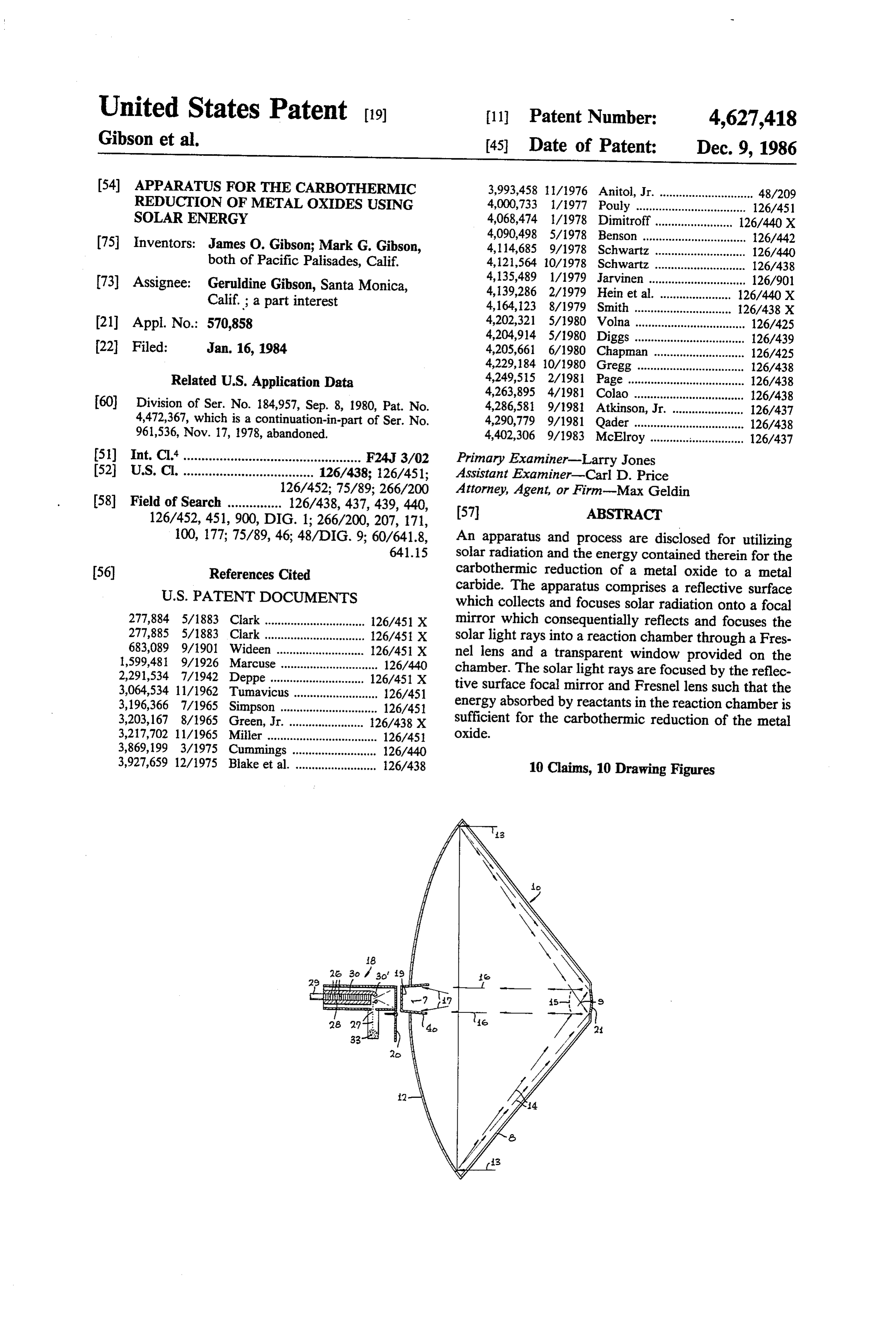
Preferably, a Fresnel lens is positioned in front of the reaction chamber along such focal pathway of light so ofFIG. 1 is a simplified lateral view partially in section apparatus of the present invention;
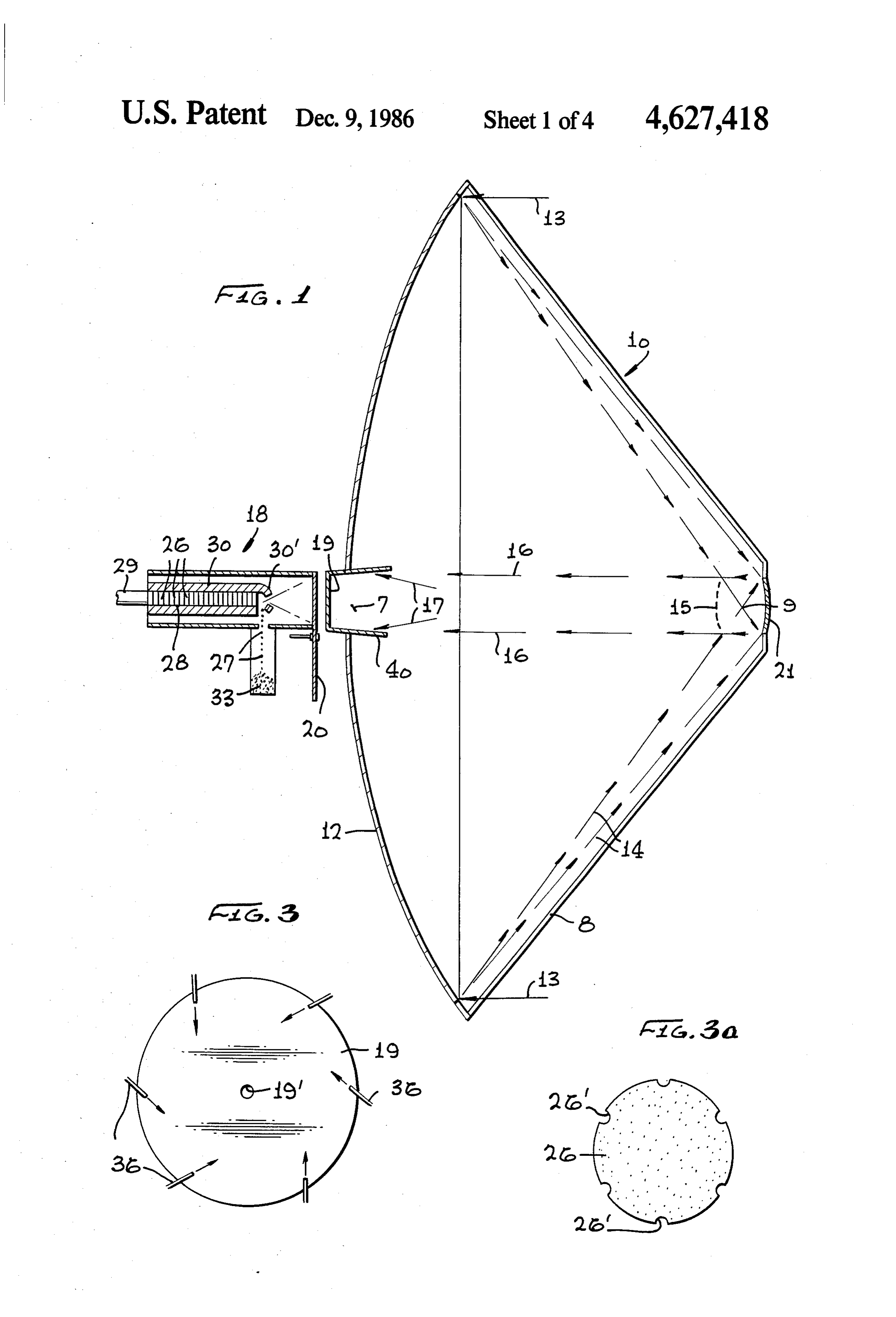
that light reflected from the focal mirror first passes 30 FIG. 2 is a cross-sectional view of the reactor section through the Fresnel lens where further focusing and of FIG. 1 above showing details of the apparatus; concentration of the solar radiation occurs. The light FIG. 3 is a side view of the Fresnel lens and the reac rays then enter the reaction chamber. A target area is tion chamber window, illustrating details of the cooling positioned within the reaction chamber in the path of jets;
the reflected light. The reaction chamber is provided 35 FIG. 3a is a side view of a reactant disc employed in with means for feeding metal oxide and carbon into the the apparatus of FIG. 2;
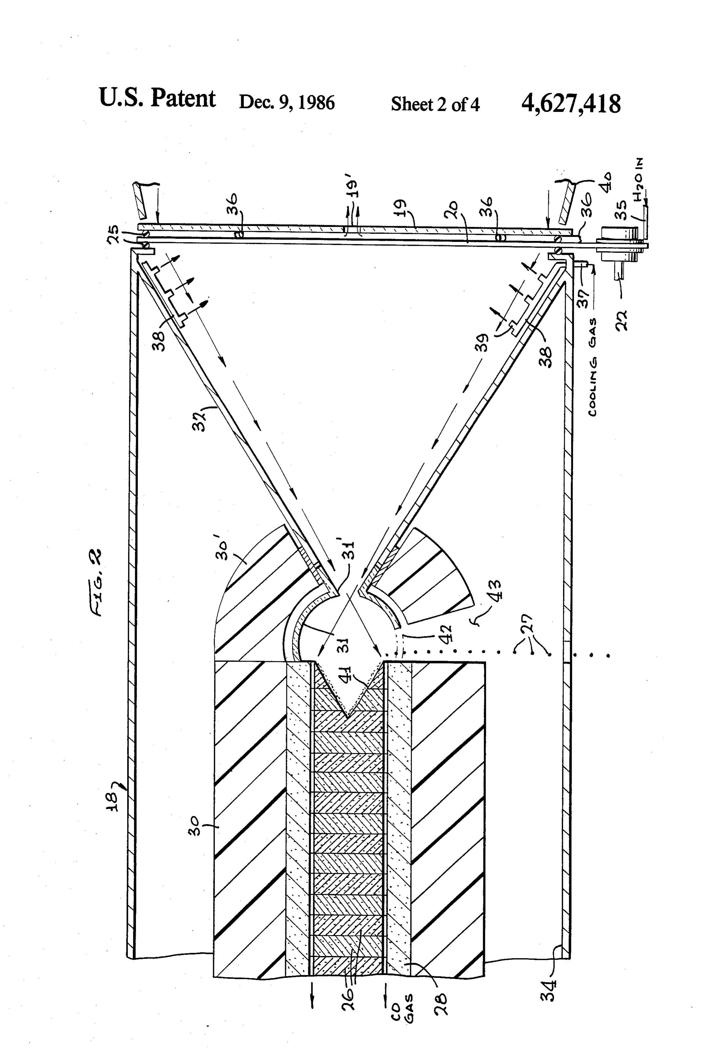
reaction chamber and target area. FIG. 4 illustrates a support and tandem arrangement In the arangement of the apparatus, the focal mirroris of apparatus of the invention;
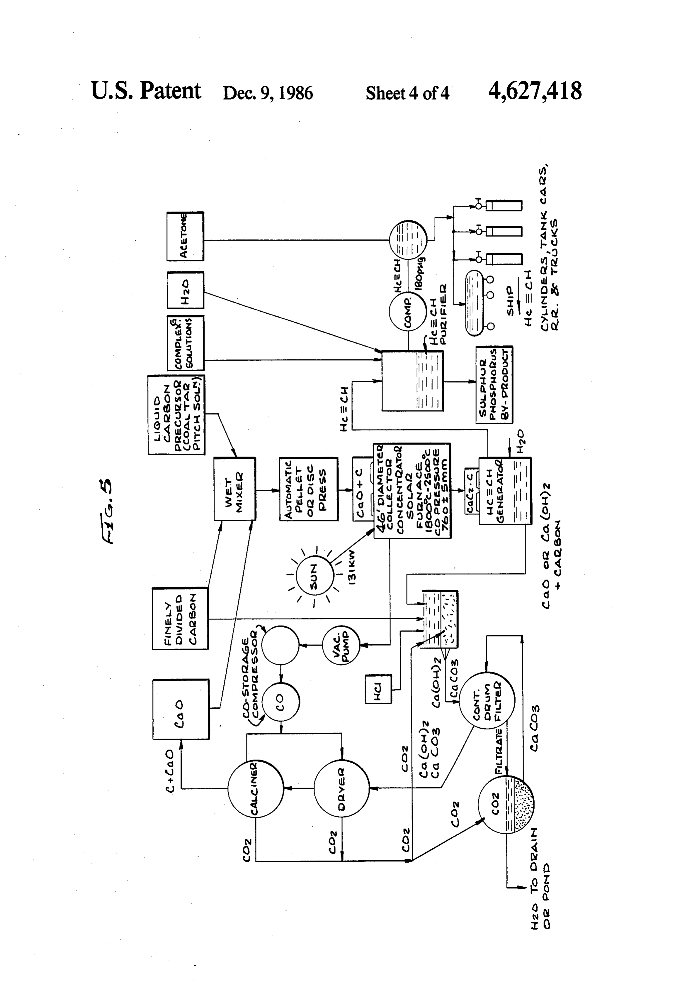
positioned between the sun and the reflective surface on FIG. 5 is a flow diagram for an overall process for the reflective side of the reflective surface. The reflec converting solar energy into a useful form of recover tive surface is directed toward the sun such that the rays able energy, and of sunlight striking the reflective surface are substan FIGS. 6 to 9 illustrate the course of the solar carbo tially parallel with its optical axis. Solar light rays strik thermic reduction reaction in forming liquid phase ing the reflective surface are collected and focused onto metal carbide and carbon.
the focal mirror. The focal mirror reflects and focuses 45 such incident solar rays toward a focal point behind the DETAILED DESCRIPTION OF THE reflective surface. The reflective surface has an opening INVENTION centrally located through which such reflected light With reference to FIG. 1 there is disclosed a simpli can pass. The reaction chamber is positioned behind the fied lateral view partially in section of one embodiment reflective surface directly in line with the reflected light 50 of the apparatus of the present invention. The apparatus rays and axially aligned with the focal mirror, the Fres provides a means for converting solar energy into a nel lens and the opening in the reflective surface. The more useful form of energy. Primarily, the apparatus reaction chamber has a light transmitting window on an utilizes solar energy to bring about an endothermic end directed toward the opening in the reflective sur chemical reaction and, more specifically, to initiate and face and the focal mirror. The light transmitting win 55 sustain the carbothermic reduction of a metal oxide. dow permits the concentrated and reflected light to Throughout the detailed description of the embodi enter the reaction chamber. Such a window can be ments of the present invention, like numerals will corre made from material selected from the group consisting spond to like elements in the figures. of quartz, Pyrex, sapphire and Vycor (trademarked The apparatus 10 comprises a first reflective surface brand of glass made by Corning Glass Works). The 60 12, preferably of polished aluminum, having an optical light transmitting window can be equipped with means axis and focal distance along such optical axis. The first for cooling the window. The window can be cooled to reflective surface 12 can be of any configuration which prevent harmful effects due to the high energy level of allows collection, reflection and focusing of light rays the concentrated rays of light being transmitted through incident to its surface. Preferably, the reflective surface the window. As the window revolves, a different area is 65 is parabolic in shape. A parabolic reflective surface presented to the high energy light rays thereby dissipat provides effective collection and focusing of light rays ing the energy absorbed by the window. The revolving incident to its surface. Incident rays 13 which strike the of the window can also allow continual cleaning of the reflective surface 12 are reflected in a converging path
Page 8
14 upon a focal mirror 21. The reflective face of the sapphire (Al2O3) and Vicor, a trademark of a glass focal mirror 21 is directed toward the reflective surface made by Corning Glass Works. The reaction chamber 12. The configuration of the focal mirror 21 is depen 18 can be provided with a water jacket 34 for cooling dent upon its location in relation to the focal point of the the reaction chamber.
reflective surface 12. In one embodiment of this inven Referring to FIGS. 1 and 2, due to the large energy tion, illustrated in FIG. 1, a focal mirror can be placed flux through the Fresnel lens 19 and the window 20, it between the reflective surface 12 and the focal point 9 is necessary to cool these transparent windows. In the of the reflective surface 12. When a focal mirror is preferred embodiment the window is revolved about an placed between the focal point and the reflective sur axis perpendicular to its surface for cooling. A motor face 12, the focal mirror generally indicated by dotted O (not shown), such as a conventional electric motor, can lines at 15 in FIG. 1, has a convex hyperboloid configu be used to revolve the window on a shaft 22. The win ration. In a preferred embodiment, the focal mirror as at dow 20 effectively seals the end of the reaction chamber 21 is placed beyond the focal point of the reflective 18 by placing "O" rings 25, e.g. formed of boron nitride, surface 12. Mirror 21 has a generally concave ellipsoid between the window and reaction chamber and be confiruration. The focal mirror 15 or 21 is positioned 15 tween the window and the Fresnel lens. As the window between the reflective surface 12 and the sun. The shad revolves, a new area of the window is exposed to the ing effect of the focal mirror on the reflective surface concentrated light rays 16. The area of the window can be taken into consideration when designing and previously exposed to the light rays can be cooled by determining the size of the reflective surface 12. The cooling means such as by coolant fluid flow directed focal mirror is sufficiently small in comparison to the 20 toward the outer surface of the window 20. It is pre reflective surface 12 and the reflective surface is suffi ferred to direct the cooling fluid, such as water, onto ciently large that the shading of the reflective surface the outer surface of window 20, by water jets 35, to by the focal mirror is small or negligible. prevent any coolant remaining on the window from As illustrated in FIG. 1, the focal mirror as shown at entering the reaction chamber. Further cooling of win 21 can be supported by struts 8 attached to the reflec 25 dow 20 can be accomplished by passing compressed CO tive surface 12. The struts 8 serve to maintain the focal cooling gas through pipe 37 into a manifold 38 within mirror 21 in proper alignment with the reflective sur the reaction chamber 18 and discharging the CO gas face 12 and the opening 7 in the reflective surface such from distributors 39 against the inside surface of the that the light rays 16 reflected from the focal mirror window 20. Referring also to FIG. 3, the Fresnel lens 19 pass through the opening 7. The struts 8 can be hollow 30 in FIG. 2 can be cooled by blowing compressed air tubes which can provide cooling fluid, such as water, to between the window 20 and the Fresnel lens 19 with the focal mirror to keep the focal mirror cool and pre appropriate air jets 36 which pass through the O-ring vent heat buildup due to the concentrated solar radia seal 25 between window 20 and lens 19. The cooling air tion focused onto the focal mirror from the reflective exits through a small central aperture 19’ in the Fresnel surface 12. Thus, the light rays 14 striking the focal 35 lens.
mirror 15 or 21 are reflected along the pathway 16 The inner surface of the window 20, i.e., the surface shown in the drawing. The focal mirror 15 or 21 focuses facing inward, can have a film or deposit formed the light incident to its surface such that the reflected thereon due to the reaction occurring within the reac light travels in a generally parallel pathway 16, having tion chamber. For example, a deposit of carbon can a focal point at infinity, toward a Fresnel lens 19 posi form on the window. Such a film or deposit can inter tioned in front of a reaction chamber 18 and along its fere with the transmission of light through the window focal pathway of light. It is preferred in this embodi and thereby decrease the amount of light energy trans ment of the invention that the Fresnel lens 19 be behind mitted into the reaction chamber. Further, such a film the reflective surface 12. To position the Fresnel lens or deposit can also cause additional heating of the win behind the reflective surface, the reflective surface 12 is 45 dow due to the increased absorption of light energy. By provided with an opening 7 which allows the reflected revolving the window 20, the inner surface of the win light to pass therethrough. The opening is generally dow can be periodically or continuously cleaned by slightly larger than the diameter of the focal mirror 21 cleaning means (not shown) for removing films or de because the reflected light rays 16 are parallel. posits formed thereon. Such cleaning means can be a The opening 7 and the focal mirror are centrally and 50 brush, a knife blade, squeegee and the like and can be axially positioned relative to the reflective surface. The positioned to clean any film or deposit from the window opening 7 is within the area of the reflective surface that as the window revolves.
is shaded by the focal mirror, therefore, little of the Referring again to FIGS. 1 and 2, the light rays 16 reflective property of the reflective surface is lost due to reflected from the focal mirror 21 pass through the such opening. 55 Fresnel lens 19 and the window 20 and continue into the Behind the reflective surface 12 and Fresnel lens 19, reaction chamber 18. A target area 26 is positioned in and positioned axially in line with the focal mirror 21 the light pathway such that the energy striking the and opening 7 in the reflective surface is the reaction target area is sufficient to initiate and sustain the carbo chamber 18. The reaction chamber wherein the carbo thermic reduction of a metal oxide. In the preferred thermic reduction of a metal oxide occurs has a trans 60 embodiment, at least one additional reflective surface is parent window 20 for transmitting reflected light rays positioned between the target area 26 and the focal into the chamber. The window 20 can be constructed mirror 21. Such reflective surfaces can be parabolic or from any transparent material. However, due to the conical. A cone reflector 40 which can be formed of concentrated solar rays striking and passing through the electropolished aluminum can be employed. Such addi window, it is necessary that the window be able to 65 tional reflective surfaces are provided for directing withstand the high energy flux and elevated tempera slightly off axis reflected light rays 17 from the focal ture generated thereby. Suitable materials for construc mirror 21, which are not in focus with the majority of tion of the window 20 include Pyrex, quartz (SiO2), the light rays 16 reflected from the focal mirror 21, in
Page 9
the direction of the target area 26, and increase the reacted surface to an energy flux sufficient to complete efficiency of the apparatus. the endothermic reaction at which point the carbide Generally, the amount of energy required to initiate produced will become liquid and flow. The automatic and sustain the carbothermic reduction is an energy transfer of liquid carbide from the reaction zone to a sufficient to maintain a temperature of at least about collection chamber is another feature of the process. As 1800° C. at the target area. Preferably, an energy pro the reaction proceeds and consumes the reactant discs ducing temperature of from about 1800 to about 2500 26, a conical cavity 41 is formed in the discs subjected to C. is suitable for initiating and sustaining the carbother heating by the photon flux, at the reaction front. mic reduction reaction. While the carbothermic reduc Also, within the reaction chamber 18 in front of the tion of some metal oxides can occur attemperatures less 10 target area 26 is a refractory reflective hemisphere 31 than 1800 C., such reaction occurs at a relatively slow insulated by Grafelt insulation cover 30', and having a rate. The carbothermic reduction reaction occurs at a throat 31' for passage of light rays transmitted through faster rate as the temperature increases and, for this the Fresnel lens 19 and the reaction chamber window reason, a temperature of at least about 1800° C. is pre 20, into the target area 26. The reflective hemisphere 31 ferred and even more preferred is a temperature range 15 and insulation cover 30' have apertures 42 and 43, re of from 1800 to about 2500 C. Generally, the amount spectively, therein, to permit passage of liquid metal of energy required to generate these preferred tempera carbide 27 therethrough. Such reflective hemisphere tures at the target area is an energy density from about has a cone reflector section 32 connected to throat 31' 560 to about 840 watts/cm2. For example, the carbo and which diverges in the direction of the window 20 of thermic reduction of calcium oxide (CaO) with carbon 20 the reaction chamber for diverting solar radiation in a to form calcium carbide (CaC2) requires about 1500 to converging pathway to the throat 31' of the refractory about 3000 watts per pound of CaC2 formed, R. Norris hemisphere 31. The reflective hemisphere 31 and inte Shreve, The Chemical Process Industries, 1st Ed., p. grally connected cone reflector section 32 can be 325 (1945). The actual energy required for the carbo formed of a reflective refractory material, e.g. polished thermic reduction reaction depends upon the metal 25 titanium carbide.
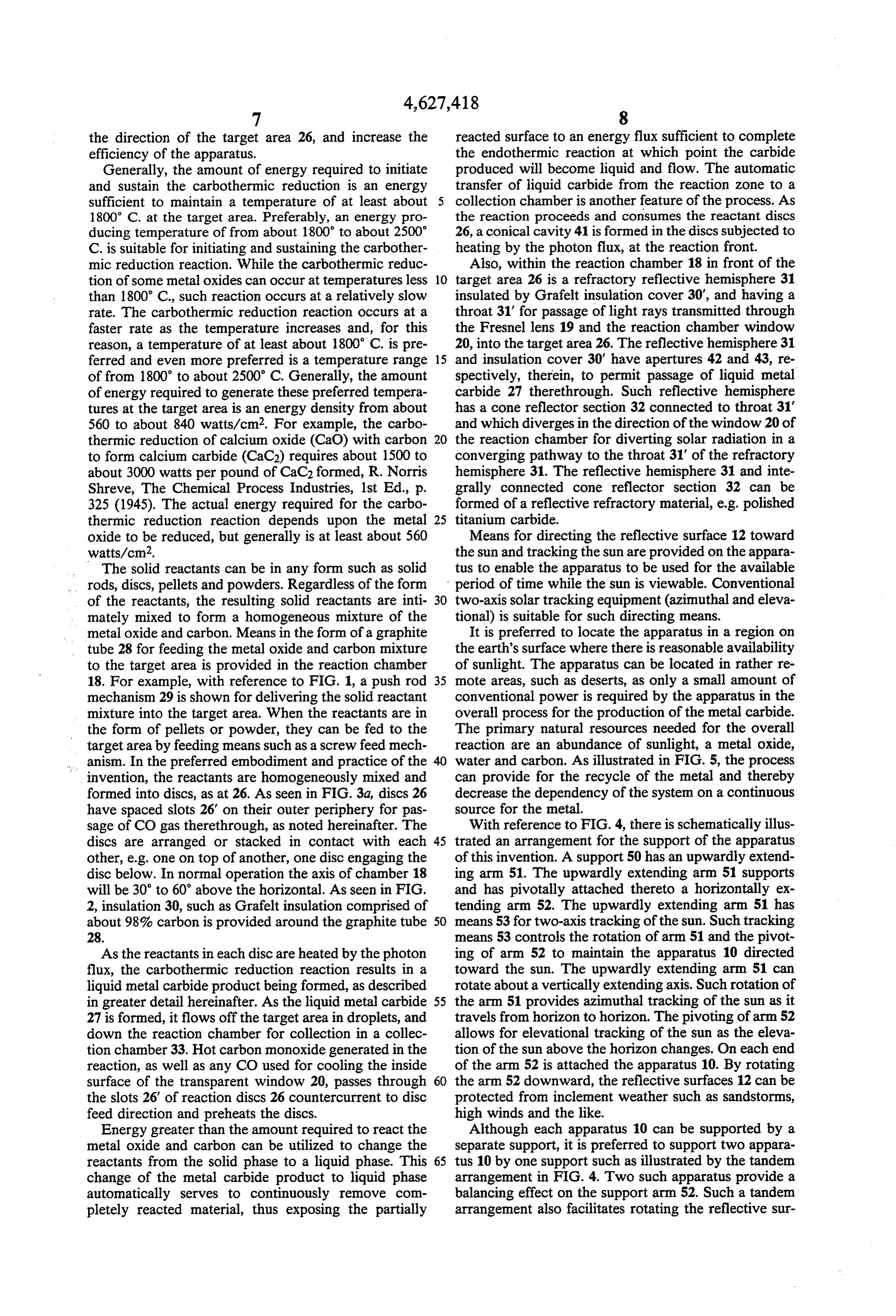
oxide to be reduced, but generally is at least about 560 Means for directing the reflective surface 12 toward watts/cm2. the sun and tracking the sun are provided on the appara The solid reactants can be in any form such as solid tus to enable the apparatus to be used for the available rods, discs, pellets and powders. Regardless of the form period of time while the sun is viewable. Conventional of the reactants, the resulting solid reactants are inti 30 two-axis solar tracking equipment (azimuthal and eleva mately mixed to form a homogeneous mixture of the tional) is suitable for such directing means. metal oxide and carbon. Means in the form of a graphite It is preferred to locate the apparatus in a region on tube 28 for feeding the metal oxide and carbon mixture the earth's surface where there is reasonable availability to the target area is provided in the reaction chamber of sunlight. The apparatus can be located in rather re 18. For example, with reference to FIG. 1, a push rod 35 mote areas, such as deserts, as only a small amount of mechanism 29 is shown for delivering the solid reactant conventional power is required by the apparatus in the mixture into the target area. When the reactants are in overall process for the production of the metal carbide. the form of pellets or powder, they can be fed to the The primary natural resources needed for the overall target area by feeding means such as a screw feed mech reaction are an abundance of sunlight, a metal oxide, anism. In the preferred embodiment and practice of the water and carbon. As illustrated in FIG. 5, the process invention, the reactants are homogeneously mixed and can provide for the recycle of the metal and thereby formed into discs, as at 26. As seen in FIG. 3a, discs 26 decrease the dependency of the system on a continuous have spaced slots 26 on their outer periphery for pas source for the metal.
sage of CO gas therethrough, as noted hereinafter. The With reference to FIG. 4, there is schematically illus discs are arranged or stacked in contact with each 45 trated an arrangement for the support of the apparatus other, e.g. one on top of another, one disc engaging the of this invention. A support 50 has an upwardly extend disc below. In normal operation the axis of chamber 18 ing arm 51. The upwardly extending arm 51 supports will be 30 to 60 above the horizontal. As seen in FIG. and has pivotally attached thereto a horizontally ex 2, insulation 30, such as Grafelt insulation comprised of tending arm 52. The upwardly extending arm 51 has about 98% carbon is provided around the graphite tube 50 means 53 for two-axis tracking of the sun. Such tracking 28. means 53 controls the rotation of arm 51 and the pivot As the reactants in each disc are heated by the photon ing of arm 52 to maintain the apparatus 10 directed flux, the carbothermic reduction reaction results in a toward the sun. The upwardly extending arm 51 can liquid metal carbide product being formed, as described rotate about a vertically extending axis. Such rotation of in greater detail hereinafter. As the liquid metal carbide 55 the arm 51 provides azimuthal tracking of the sun as it 27 is formed, it flows off the target area in droplets, and travels from horizon to horizon. The pivoting of arm 52 down the reaction chamber for collection in a collec allows for elevational tracking of the sun as the eleva tion chamber 33. Hot carbon monoxide generated in the tion of the sun above the horizon changes. On each end reaction, as well as any CO used for cooling the inside of the arm 52 is attached the apparatus 10. By rotating surface of the transparent window 20, passes through 60 the arm 52 downward, the reflective surfaces 12 can be the slots 26 of reaction discs 26 countercurrent to disc protected from inclement weather such as sandstorms, feed direction and preheats the discs. high winds and the like.
Energy greater than the amount required to react the Although each apparatus 10 can be supported by a metal oxide and carbon can be utilized to change the separate support, it is preferred to support two appara reactants from the solid phase to a liquid phase. This 65 tus 10 by one support such as illustrated by the tandem change of the metal carbide product to liquid phase arrangement in FIG. 4. Two such apparatus provide a automatically serves to continuously remove com balancing effect on the support arm 52. Such a tandem pletely reacted material, thus exposing the partially arrangement also facilitates rotating the reflective sur
Page 10
faces 12 downward during inclement weather condi into the position where the diverging photon beam will tions. Also, by providing a tandem arrangement, one have a diameter of 15 cm. This position is about 16 cm. two-axis solar tracking means 53 can be utilized to di past the focal point.
rect and maintain the two reflective surfaces 12 toward A process for the carbothermic reduction of a metal the sun. oxide using the above described apparatus is practiced The sizes of the various elements of the apparatus are by first preparing the reactant material to be reduced. not critical as long as the required energy to initiate and Such reactant material to be reduced comprises a homo sustain the carbothermic reduction reaction of the metal geneous mixture of carbon and a reducible metal oxide. oxide is developed at the target area. An apparatus The metal oxide can be any suitable metal oxide which which has a reflective surface 12 of about 46 feet in 10 is capable of carbothermic reduction. Such metal oxide diameter and a focal distande of about 23 feet, will be can be any of those previously noted such as calcium described herein to illustrate possible relative sizes of oxide or aluminum oxide.
the various elements of the apparatus. With reference The carbon in the homogeneous mixture is present in again to FIGS. 1 and 2, the reflective surface 12 can be a stoichiometric excess over the amount required to a parabolic reflective surface about 46 feet in diameter, 15 produce the metal carbide. Such excess carbon can be in with a focal length of about 23 feet. A concave ellipsoid a particular range of molar ratios to the metal oxide focal mirror 21, having a diameter of about 3.3 feet and depending upon the valence or valences of such se a focal distance at infinity is suspended about 1.5 feet lected metal in the metal oxide, in order to provide a behind the focal point, or about 25 feet in front of the reaction, in conjunction with sufficiently high tempera reflective surface 12. Light rays reflected from the focal 20 ture wherein the metal carbide is in the liquid phase, mirror are directed toward an opening 7 of about 3.3 particularly as discussed hereafter. The excess carbon feet in diameter in the center of the reflective surface 12. increases the light absorptivity of the mixture, i.e., the A cone reflector 40 receives a small portion of the light essentially black carbon allows for about 98 percent which is slightly divergent from the 1-meter in diameter absorption of light for the entire solar spectrum. There beam of light reflected from the focal mirror 21. This 25 fore, for example, a target material to be reduced, can divergent light together with parallel rays of light fall comprise a mixture of calcium oxide and carbon in a on the Fresnel lens 19 which has a focal distance of molar ratio of from about 1 to 3.1 to about 1 to 4 respec about 800 cm.
tively, in order to absorb solar photons. For aluminum
A reaction chamber 18 axially aligned with the open oxide, the target mixture can comprise aluminum oxide ing and focal mirror is attached to the reflective surface 30 and carbon in a molar ratio of from about 2 to 9.1 to 12. A target area of about 314 cm2 is located within the about 2 to 10, respectively. For the rare earths the ratio reaction chamber about one meter behind the reflective of metal oxide such as neodymium and praseodymium, surface 12. The light transmitting window 20 has an to carbon can range from about 1 to 6.1 to about 1 to 7. effective window diameter relative to the chamber of Preferably, the reactants are substantially pure and about 1.0 meter and an overall diameter of about 2.2 35 the reactant mixture made therefrom is substantially meters to provide for such an effective window size. free of materials other than the metal oxide and carbon. Any shadow cast on the reflective surface 12 caused by By using substantially pure feed material, the possibility the shading effect of focal mirror 21 is about 1 meter in of competing chemical reactions other than the carbo diameter. Such a shadow provides minimal loss of effec thermic reaction is limited.
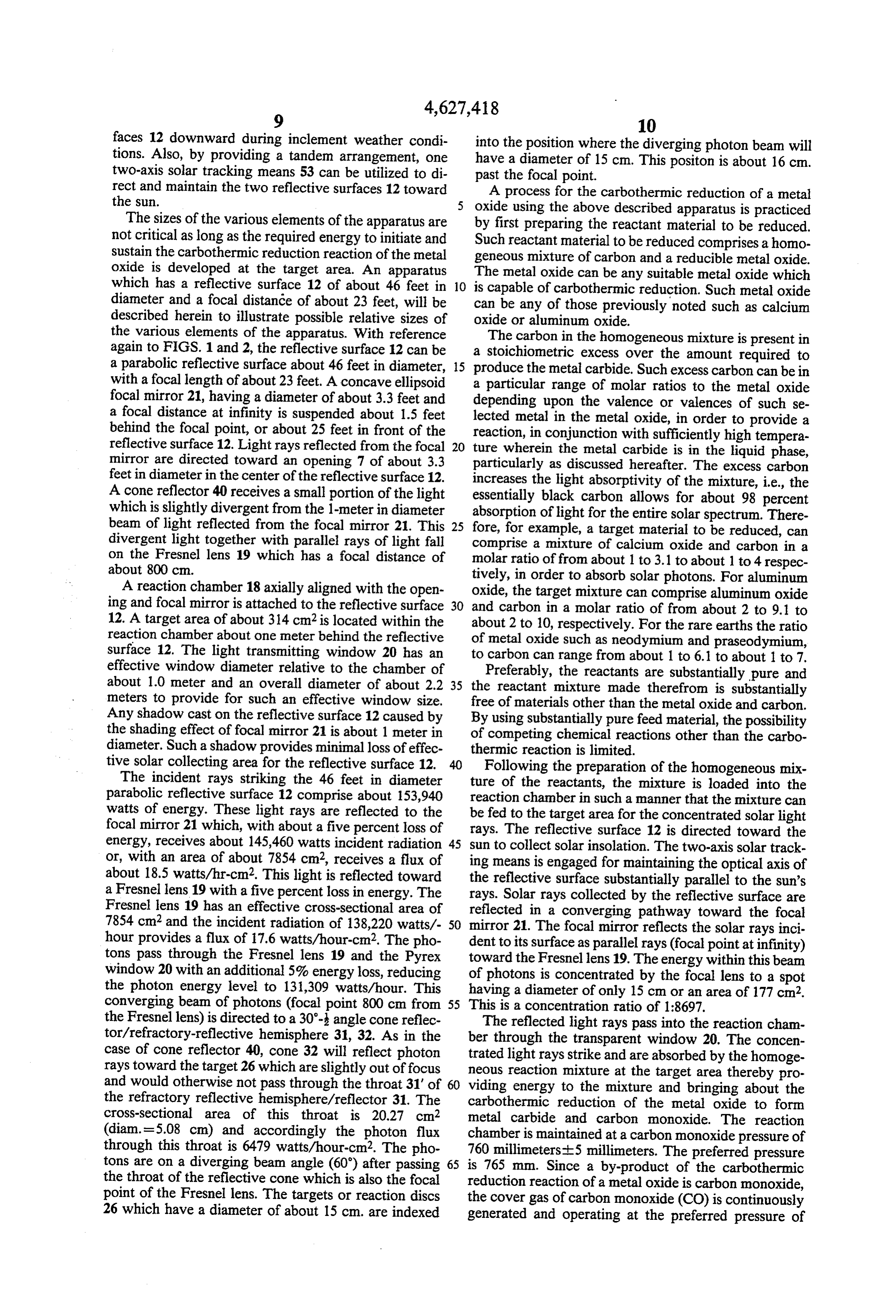
tive solar collecting area for the reflective surface 12. Following the preparation of the homogeneous mix The incident rays striking the 46 feet in diameter ture of the reactants, the mixture is loaded into the parabolic reflective surface 12 comprise about 153,940 reaction chamber in such a manner that the mixture can watts of energy. These light rays are reflected to the be fed to the target area for the concentrated solar light focal mirror 21 which, with about a five percent loss of rays. The reflective surface 12 is directed toward the energy, receives about 145,460 watts incident radiation 45 sun to collect solar insolation. The two-axis solar track or, with an area of about 7854 cm2, receives a flux of ing means is engaged for maintaining the optical axis of about 18.5 watts/hr-cm2. This light is reflected toward the reflective surface substantially parallel to the sun's a Fresnel lens 19 with a five percent loss in energy. The rays. Solar rays collected by the reflective surface are Fresnel lens 19 has an effective cross-sectional area of reflected in a converging pathway toward the focal 7854 cm2 and the incident radiation of 138,220 watts/- 50 mirror 21. The focal mirror reflects the solar rays inci hour provides a flux of 17.6 watts/hour-cm2. The pho dent to its surface as parallel rays (focal point at infinity) tons pass through the Fresnel lens 19 and the Pyrex toward the Fresnel lens 19. The energy within this beam window 20 with an additional 5% energy loss, reducing of photons is concentrated by the focal lens to a spot the photon energy level to 131,309 watts/hour. This having a diameter of only 15 cm or an area of 177 cm2. converging beam of photons (focal point 800 cm from 55 This is a concentration ratio of 1:8697. the Fresnel lens) is directed to a 30- angle cone reflec tor/refractory-reflective hemisphere 31, 32. As in the berThe reflected light rays pass into the reaction cham through the transparent window 20. The concen case of cone reflector 40, cone 32 will reflect photon trated light rays strike and are absorbed by the homoge rays toward the target 26 which are slightly out of focus neous reaction mixture at the target area thereby pro and would otherwise not pass through the throat 31' of 60 viding energy to the mixture and bringing about the the refractory reflective hemisphere/reflector 31. The carbothermic reduction of the metal oxide to form cross-sectional area of this throat is 20.27 cm2 metal carbide and carbon monoxide. The reaction (diam. =5.08 cm) and accordingly the photon flux through this throat is 6479 watts/hour-cm2. The pho chamber is maintained at a carbon monoxide pressure of 760 millimeters--5 millimeters. The preferred pressure tons are on a diverging beam angle (60) after passing 65 is 765 mm. Since a by-product of the carbothermic the throat of the reflective cone which is also the focal reduction reaction of a metal oxide is carbon monoxide, point of the Fresnel lens. The targets or reaction discs the cover gas of carbon monoxide (CO) is continuously 26 which have a diameter of about 15 cm. are indexed generated and operating at the preferred pressure of
Page 11
about 765 mm. The CO gas is continuously expelled reduction occurs during the time period the sun is avail from the reaction chamber and is collected for further able to provide the necessary energy. The proper processing. amount of reactant mixture that enables total utilization Due to the presence of the large excess of carbon of the available solar energy can be loaded into the noted above, and the above noted high reaction temper reaction chamber at a time when the sun is not available atures (about 1800 to about 2500 C.), the carbothermic or the solar rays are insufficient to initiate the reaction. reduction reaction takes place in the liquid phase. By The rate of feeding the homogeneous mixture to the virtue of the carbon-rich composition and high temper target area can be controlled to coincide with the speed atures, solar photon energy is absorbed in the liquid of the reaction occurring at the target area. For exam phase. Thus, as the carbothermic reduction occurs, the O ple, if the sun is obscured by thin clouds, the feeding liquid metal carbide formed drips from the target area in means can operate at a slower speed than on a clear day the reaction chamber. or when the sun is not obscured. Referring now to FIGS. 6 to 9 of the drawing, there When the sun has set or when the energy level of the is illustrated the photon absorption, heat transfer mech solar rays has become inadequate to initiate and sustain anisms and production of the preferred CaC2(1).C(s) 15 the carbothermic reduction, the metal carbide produced composition, that is, calcium carbide in liquid phase can be removed from the reaction chamber. containing an equimolar amount of carbon.
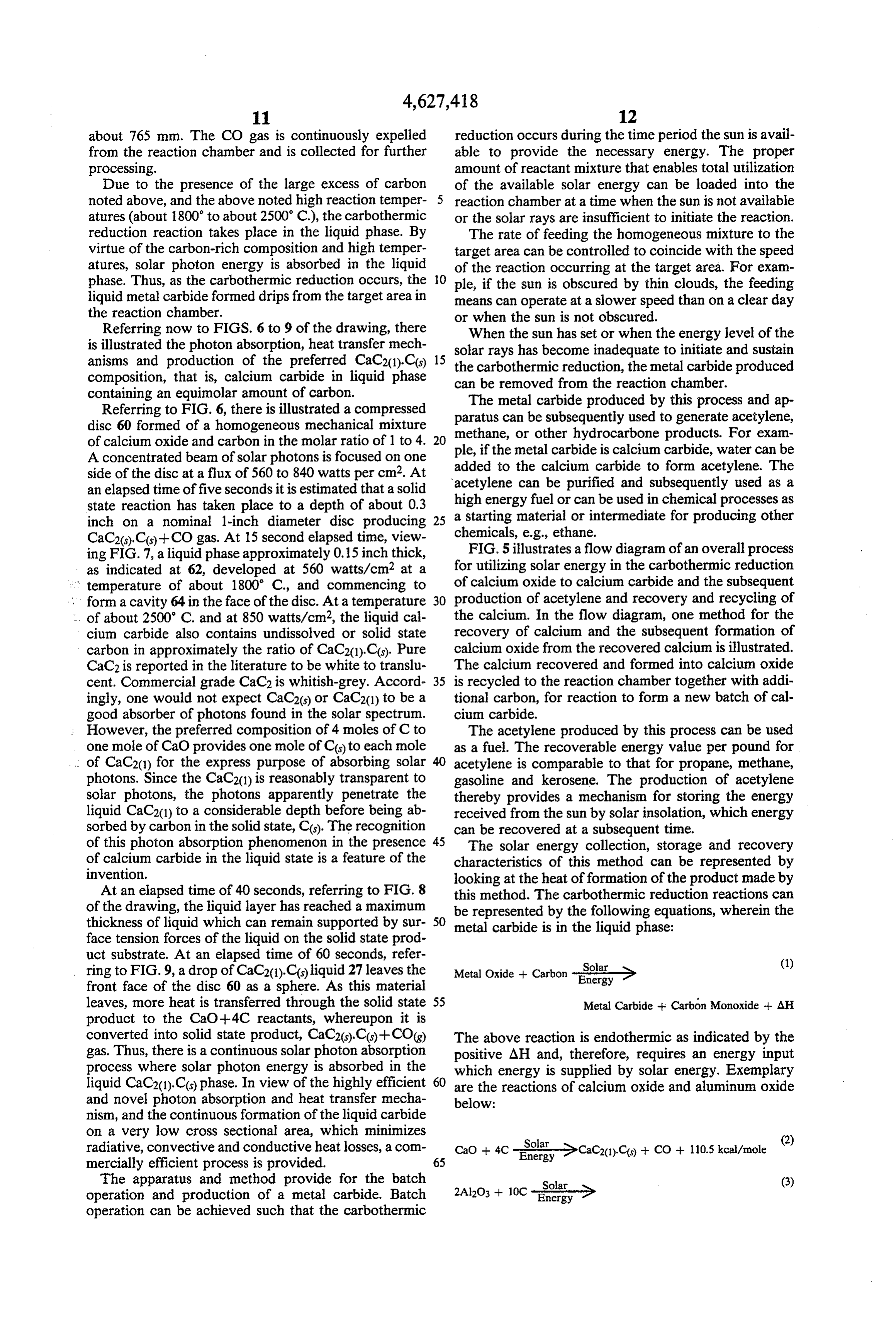
Referring to FIG. 6, there is illustrated a compressed paratus can be subsequently usedbytothis The metal carbide produced process and ap generate acetylene, disc 60 formed of a homogeneous mechanical mixture methane, or other hydrocarbone products. For exam of calcium oxide and carbon in the molar ratio of 1 to 4. 20 ple, if the metal carbide is calcium carbide,
A concentrated beam of solar photons is focused on one added to the calcium carbide to form acetylene. The water can be side of the disc at a flux of 560 to 840 watts per cm2. At acetylene can be purified and subsequently used as a an elapsed time of five seconds it is estimated that a solid state reaction has taken place to a depth of about 0.3 ahigh energy fuel or can be used in chemical processes as starting material or intermediate for producing other inch on a nominal 1-inch diameter disc producing 25
CaC2(s),C(s)--CO gas. At 15 second elapsed time, view chemicals, e.g., ethane.
FIG. 5 illustrates a flow diagram of an overall process ing FIG. 7, a liquid phase approximately 0.15 inch thick, as indicated at 62, developed at 560 watts/cm2 at a for utilizing solar energy in the carbothermic reduction temperature of about 1800° C., and commencing to of calcium oxide to calcium carbide and the subsequent form a cavity 64 in the face of the disc. At a temperature 30 production of acetylene and recovery and recycling of . . of about 2500 C. and at 850 watts/cm2, the liquid cal the calcium. In the flow diagram, one method for the cium carbide also contains undissolved or solid state recovery of calcium and the subsequent formation of carbon in approximately the ratio of CaC2(1).C(s). Pure calcium oxide from the recovered calcium is illustrated. CaC2 is reported in the literature to be white to translu The calcium recovered and formed into calcium oxide cent. Commercial grade CaC2 is whitish-grey. Accord 35 is recycled to the reaction chamber together with addi ingly, one would not expect CaC2(s) or CaC2(1) to be a tional carbon, for reaction to form a new batch of cal good absorber of photons found in the solar spectrum. cium carbide.
: However, the preferred composition of 4 moles of C to The acetylene produced by this process can be used one mole of CaO provides one mole of Cos) to each mole as a fuel. The recoverable energy value per pound for . . of CaC2(1) for the express purpose of absorbing solar acetylene is comparable to that for propane, methane, photons. Since the CaC2(1) is reasonably transparent to gasoline and kerosene. The production of acetylene solar photons, the photons apparently penetrate the thereby provides a mechanism for storing the energy liquid CaC2(1) to a considerable depth before being ab received from the sun by solar insolation, which energy sorbed by carbon in the solid state, C(s). The recognition can be recovered at a subsequent time. of this photon absorption phenomenon in the presence 45 The solar energy collection, storage and recovery of calcium carbide in the liquid state is a feature of the characteristics of this method can be represented by invention. looking at the heat of formation of the product made by At an elapsed time of 40 seconds, referring to FIG. 8 this method. The carbothermic reduction reactions can of the drawing, the liquid layer has reached a maximum be represented by the following equations, wherein the thickness of liquid which can remain supported by sur 50 metal carbide is in the liquid phase: face tension forces of the liquid on the solid state prod uct substrate. At an elapsed time of 60 seconds, refer (1) ring to FIG.9, a drop of CaC2(1).C(s) liquid 27 leaves the Metal Oxide -- Carbon -i > front face of the disc 60 as a sphere. As this material leaves, more heat is transferred through the solid state 55 Metal Carbide + Carbón Monoxide + AH product to the CaO +4C reactants, whereupon it is converted into solid state product, CaC2(s)..Cs)+CO(g) The above reaction is endothermic as indicated by the gas. Thus, there is a continuous solar photon absorption positive AH and, therefore, requires an energy input process where solar photon energy is absorbed in the which energy is supplied by solar energy. Exemplary liquid CaC2(1).C(s) phase. In view of the highly efficient 60 are the reactions of calcium oxide and aluminum oxide and novel photon absorption and heat transfer mecha below:
nism, and the continuous formation of the liquid carbide on a very low cross sectional area, which minimizes 2 radiative, convective and conductive heat losses, a com CaO -- 4C -i >CaC20) Co. + CO+ 110.5 kcal/mole mercially efficient process is provided. 65
The apparatus and method provide for the batch (3) operation and production of a metal carbide. Batch operation can be achieved such that the carbothermic
Page 12
-continued presents an economical method for creating an alterna
Al4C3(1)Cs) + 6CO + 608.9 kcal/mole tive energy source to the conventionally used fossil fuels. The sun's energy is substantially consistent and is
Depending upon the amount of excess carbon present generally being little utilized. This method provides one in the starting mixture of metal oxide and carbon, liquid method of capturing the energy of incident sunlight and metal carbide together with solid carbon, as represented of storing such energy indefinitely in a form from which by metal carbide(1).xC(s), drips or flows from the target the energy can be readily retrieved and put to use. area. Thus, the liquid phase carbothermic reductions by The apparatus herein described for conducting this means of solar energy according to the invention, using method excess carbon produces a liquid metal carbide product which bycomprises
a combination of related elements containing 0.1 to 1.0 mole carbon, per mole of liquid for collecting solar energyprovide acting together an efficient apparatus and converting that energy metal carbide, e.g. CaC2(1).0.1Cs) to CaC2(1).C(s), into a more useful, handleable and storable form of Al4C3(1).0.1C(s) to Al4C3(1),C(s), and Di2C3(1).0.1C(s) to energy. The apparatus is designed with the reaction
The solar energy absorbed by the reactants is stored 15 tion such behind chamber as for the reflective surface for ease of opera loading reactants and recovery of prod in the reaction products and primarily in the metal car uct. Further, by positioning the reaction chamber be bide formed as is represented by the following general equation: hind the reflective surface and using a double reflection of the solar light there is no need to provide strong
Metal Carbide -- Water-Metal Oxide or Metal 20 payload support elements to support a reaction chamber Hydroxide--Hydrocarbon-AH (4) as would be required when only a single reflecting and focusing surface is used. Additionally, balancing of the
The solar energy stored within the reaction products apparatus is easier with the double reflective apparatus can be stored indefinitely and can be recovered upon herein described than when a single reflective surface demand by conducting one of the above reactions rep 25 having a reaction chamber positioned thereabove is resented by equation (4) to produce a fuel such as acety used. The addition of a second light concentrating ele lene or methane. These reactions are exothermic and ment, that is a Fresnel lens, according to another feature have negative heat of formation and thereby occur of the invention, into the optical pathway of light from without additional energy input. Again, with reference a double reflecting system permits the use of reaction to a calcium oxide/calcium carbide system, the follow 30 furnace designs which can minimize conductive, con ing reaction formulae are representative: vective and particularly radiant heat losses. This final concentration of light by the Fresnel lens permits all kcal/mole (5) collected energy to be directed through a small apertu rue in a reaction chamber, blocking large heat losses and
CaC2C-i-H2O-CaO + C--HC=CH-30.0 35 increasing thermochemical energy conversion. kcal/mole (6) While the present invention has been disclosed in connection with preferred embodiments thereof, it should be understood that there can be other variations
of the invention which are within the scope thereof as
Di2C3.C+H2O-Di2O3+C+HCsCH-i-H2 (8) defined by the appended claims.
What is claimed is:
The acetylene produced from calcium carbide can be 1. Apparatus for the carbothermic reduction of a combusted as a substitute fuel for contemporary fossil metal oxide to produce a metal carbide utilizing solar fuels and upon combustion provides 310.6 kcal/mole of energy comprising:
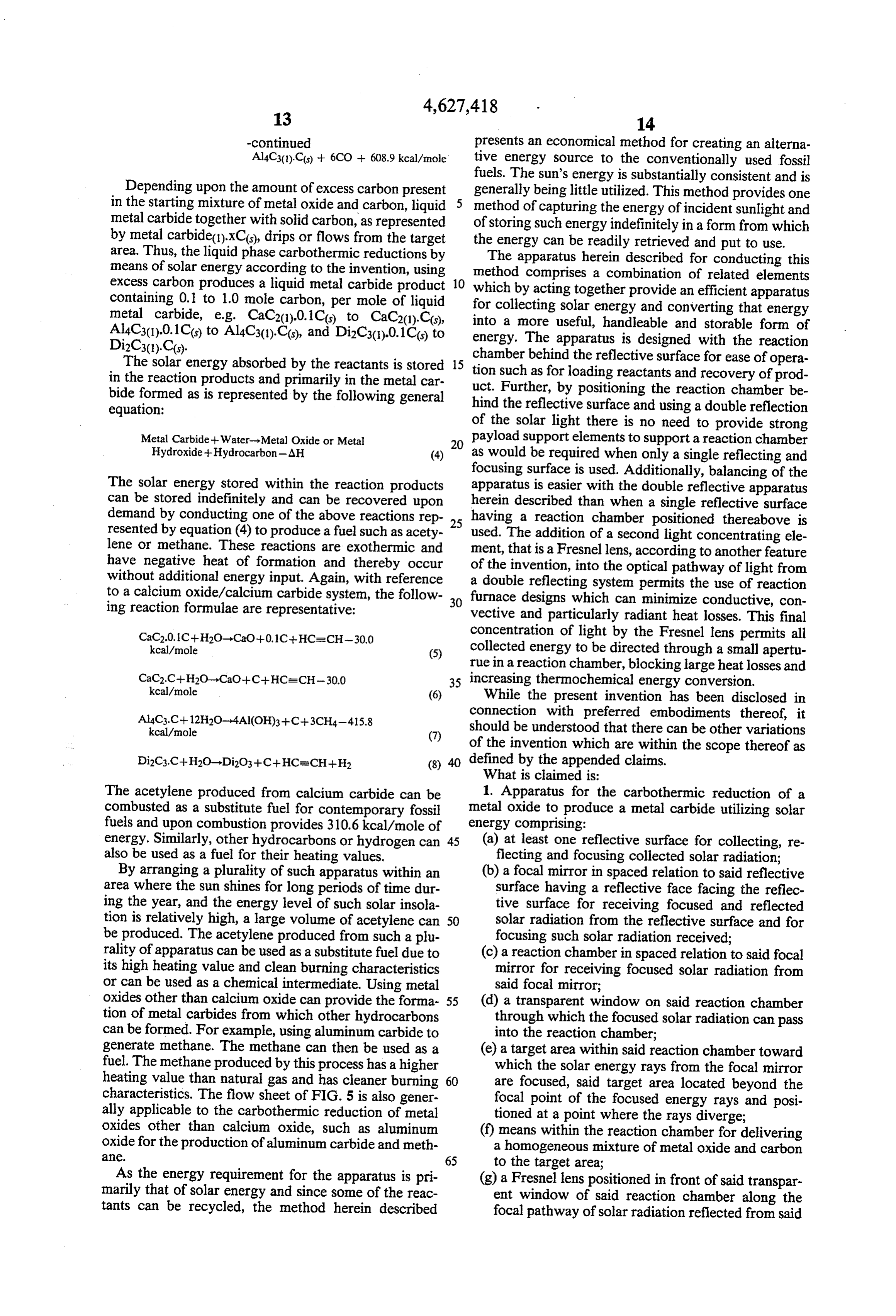
energy. Similarly, other hydrocarbons or hydrogen can 45 (a) at least one reflective surface for collecting, re also be used as a fuel for their heating values. flecting and focusing collected solar radiation; By arranging a plurality of such apparatus within an (b) a focal mirror in spaced relation to said reflective area where the sun shines for long periods of time dur surface having a reflective face facing the reflec ing the year, and the energy level of such solar insola tive surface for receiving focused and reflected tion is relatively high, a large volume of acetylene can 50 solar radiation from the reflective surface and for be produced. The acetylene produced from such a plu focusing such solar radiation received; rality of apparatus can be used as a substitute fuel due to (c) a reaction chamber in spaced relation to said focal its high heating value and clean burning characteristics mirror for receiving focused solar radiation from or can be used as a chemical intermediate. Using metal said focal mirror;
oxides other than calcium oxide can provide the forma 55 (d) a transparent window on said reaction chamber tion of metal carbides from which other hydrocarbons through which the focused solar radiation can pass can be formed. For example, using aluminum carbide to into the reaction chamber; generate methane. The methane can then be used as a (e) a target area within said reaction chamber toward fuel. The methane produced by this process has a higher which the solar energy rays from the focal mirror heating value than natural gas and has cleaner burning 60 are focused, said target area located beyond the characteristics. The flow sheet of FIG. 5 is also gener focal point of the focused energy rays and posi ally applicable to the carbothermic reduction of metal tioned at a point where the rays diverge; oxides other than calcium oxide, such as aluminum (f) means within the reaction chamber for delivering oxide for the production of aluminum carbide and meth a homogeneous mixture of metal oxide and carbon ac. 65 to the target area;
As the energy requirement for the apparatus is pri (g) a Fresnel lens positioned in front of said transpar marily that of solar energy and since some of the reac ent window of said reaction chamber along the tants can be recycled, the method herein described focal pathway of solar radiation reflected from said
Page 13
focal mirror, for further focusing and concentrat passing through said Fresnel lens and said transparent ing the solar radiation, the Fresnel lens being iso window to the target area.
lated by the transparent window from the reaction 4. Apparatus as defined in claim 3, including a refrac taking place in the reaction chamber; tory reflective hemisphere in said reaction chamber (h) means for providing a cooling fluid flow between having an inner reflective surface facing and closely the transparent window and the Fresnel lens; and adjacent said target area, for diverting solar radiation to (i) means for revolving said transparent window so the target area, a throat disposed centrally in said reflec that a different portion of said transparent window tive hemisphere and opening toward the target area, is positioned to transmit focused solar radiation to said second conical reflector connected to said throat the reaction chamber. O and diverging in the direction toward said transparent 2. Apparatus for the carbothermic reduction of a window of said reaction chamber, for directing solar metal oxide to produce a metal carbide utilizing solar radiation in a converging pathway from said Fresnel energy comprising: lens and said transparent window to said throat and into (a) at least one reflective surface for collecting, re said reflective hemisphere.
flecting and focusing collected solar radiation; 15 5. Apparatus as defined in claim 2, said means for (b) a focal mirror in spaced relation to said reflective providing a cooling fluid flow comprising a plurality of surface having a reflective face facing the reflec air jets positioned between said transparent window and tive surface for receiving focused and reflected said Fresnel lens, and also cooling said Fresnel lens. solar radiation from the reflective surface and for 6. Apparatus for the carbothermic reduction of a focusing such solar radaiation received; 20 metal oxide to produce a metal carbide utilizing solar (c) a reaction chamber in spaced relation to said focal energy comprising:
mirror for receiving focused solar radiation from (a) at least one reflective surface for collecting, re said focal mirror; flecting and focusing collected solar radiation; (d) a transparent window on said reaction chamber (b) a focal mirror in spaced relation to said reflective having a surface facing outward thereof and 25 surface having a reflective face facing the reflec through which the focused solar radiation can pass tive surface for receiving focused and reflected into the reaction chamber; solar radiation from the reflective surface and for (e) a target area within said reaction chamber toward focusing such solar radiation received; which the solar energy rays from the focal mirror (c) a reaction chamber in spaced relation to said focal are focused, said target area located beyond the 30 mirror for receiving focused solar radiation from focal point of the focused energy rays and posi said focal mirror;
tioned at a point where the rays diverge; (d) a transparent window on said reaction chamber (f) means within the reaction chamber for delivering through which the focused solar radiation can pass a homogeneous mixture of metal oxide and carbon into the reaction chamber;
to the target area; 35 (e) a target area within said reaction chamber toward (g) a Fresnel lens positioned in front of said transpar which the solar energy rays from the focal mirror ent window of said reaction chamber along the are focused and then directed on the target area by focal pathway of solar radiation reflected from said divergence of the solar rays beyond the focal point focal mirror, for further focusing and concentrat thereof;
ing the solar radiation; (f) means within the reaction chamber for delivering (h) means for providing a cooling fluid flow directed a homogeneous mixture of metal oxide and carbon to the surface of the transparent window facing to the target area; and outward of the reaction chamber and to the inside (g) means for revolving said transparent window so surface of said Fresnel lens; that a different portion of said transparent window (i) seal means between the spaced apart Fresnel lens 45 is positioned to transmit focused solar radiation to and transparent window, providing a fluid flow the reaction chamber.
passage communicating with the means for provid 7. Apparatus as defined in claim 6, wherein the trans ing said cooling fluid flow; parent window comprises a transparent material se (j) means forming an aperture in the center of said lected from the group consisting of Pyrex, quartz, sap Fresnel lens communicating with said fluid flow 50 phire and Vycor.
passage, said cooling fluid exiting through said 8. Apparatus as defined in claim 6, further comprising apertures; and means for cleaning the surface of the transparent win (k) means for revolving said transparent window so dow facing the target interiorly of the reaction cham that a different portion of said transparent window ber.
is positioned to transmit focused solar radiation to 55 9. Apparatus as defined in claim 6, wherein the means the reaction chamber. for delivering a homogenous mixture of metal oxide and 3. Apapratus as defined in claim 2, further comprising carbon to the target area comprises a push rod and a a first conical reflector inside having a reflective surface plurality of discs of said homogenous mixture, said discs and positioned between said Fresnel lens and said focal having slots for passage of reaction gas therethrough. mirror for diverting light rays not in focus from said 60 10. Apparatus as defined in claim 6, including means mirror towards the target area, and a second conical for providing a cooling fluid flow directed to the inside reflector within the reaction chamber and having an surface of the transparent k k window.
inside reflecting surface and diverting solar radiation
Provenance
- Collection
- Cited prior art
- Original PDF
- patentimages.storage.googleapis.com →
- Filed
- 1984-01-16
- Pages
- 13
- Method
- pdftotext (the PDF's own text layer) + pdftoppm 300dpi page scans
- Source
- Google Patents bibliographic record
- Granted
- 1986-12-09
- Inventors
- James O. Gibson; Mark G. Gibson
- Transcribed from
- patentimages.storage.googleapis.com →