patent · US4452232
Solar heat boiler
5 June 1984
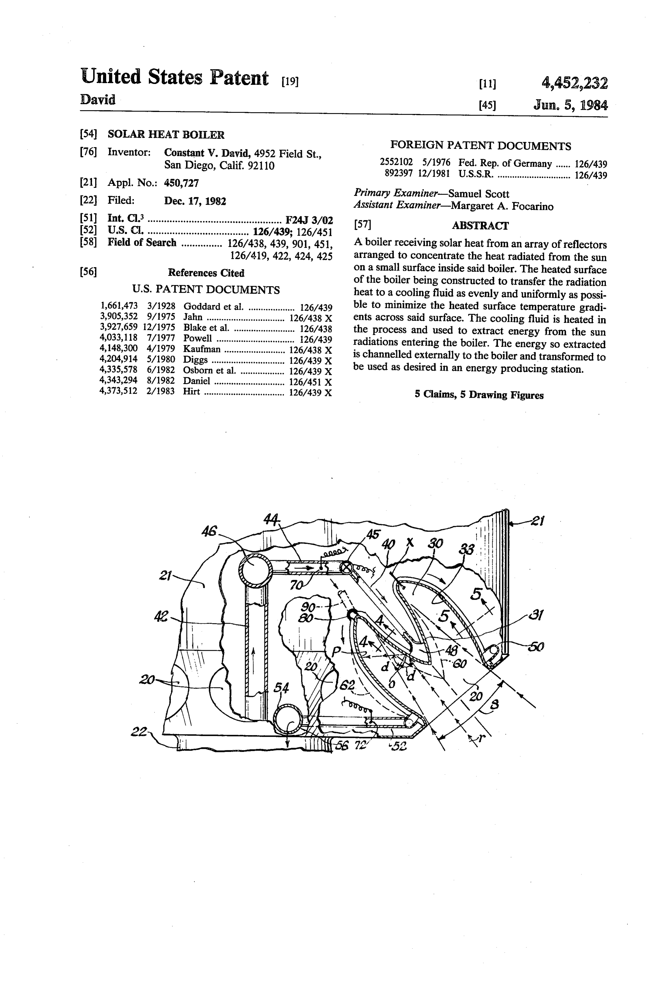
Page 1 — bibliographic record
United States Patent (19) (11) 4,452,232 David 45) Jun. 5, 1984
(54) SOLAR HEAT BOLER
FOREIGN PATENT DOCUMENTS
76 Inventor: Constant V. David, 4952 Field St.,
San Diego, Calif. 92110 2552102 5/1976 Fed. Rep. of Germany ..... 126/439 892397 12/1981 U.S.S.R. .............................. 126/439
Primary Examiner-Samuel Scott
Assistant Examiner-Margaret A. Focarino 51 int. Cl. ................................................. F24J 3/02 57 ABSTRACT 52 U.S. C. ..................................... 126/439; 126/451 58) Field of Search ............... 126/438, 439,901, 451, A boiler receiving solar heat from an array of reflectors 126/419, 422, 424, 425 arranged to concentrate the heat radiated from the sun 56 References Cited on a small surface inside said boiler. The heated surface
of the boiler being constructed to transfer the radiation heat to a cooling fluid as evenly and uniformly as possi 1,661,473 3/1928 Goddard et al. ................... 126/439 ble to minimize the heated surface temperature gradi 3,905,352 9/1975 Jahn ................. 126/438 X ents across said surface. The cooling fluid is heated in 3,927,659 12/1975 Blake et al ... 126/438 the process and used to extract energy from the sun 4,033,118 7/1977 Powell ........ ... 26/439 radiations entering the boiler. The energy so extracted
4,204,914 5/1980 Diggs .......... ... 126/439 X is channelled externally to the boiler and transformed to 4,335,578 6/1982 Osborn et al. ... 126/439 X be used as desired in an energy producing station.
4,373,512 2/1983 Hirt ..... ... 126/439 X 5 Claims, 5 Drawing Figures
Page 2
Drawing sheet — no readable text.
Page 3
Accordingly, the present invention provides a solar
SOLAR HEAT BOLER heat energy extractor that is efficient, structurally reli able and effective in transferring heat from sun radiation
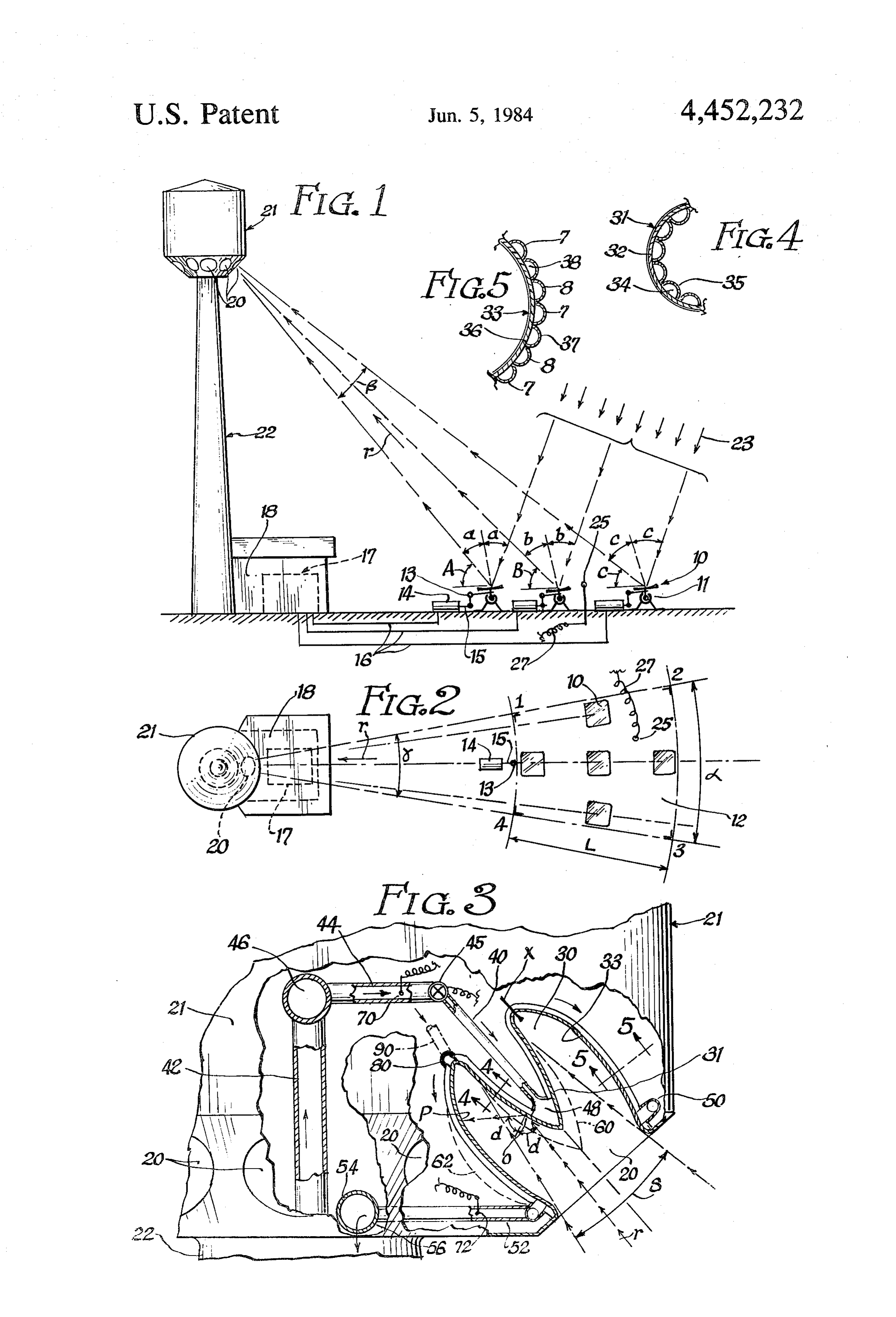
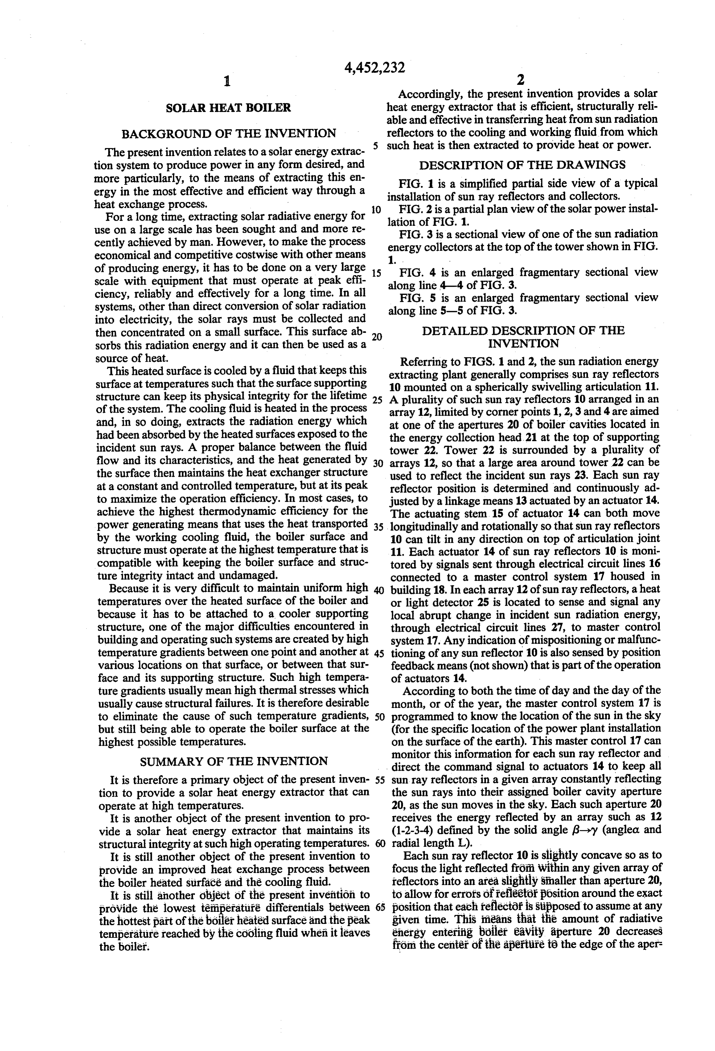
BACKGROUND OF THE INVENTION reflectors to the cooling and working fluid from which The present invention relates to a solar energy extrac such heat is then extracted to provide heat or power. tion system to produce power in any form desired, and DESCRIPTION OF THE DRAWINGS more particularly, to the means of extracting this en FIG. 1 is a simplified partial side view of a typical ergy in the most effective and efficient way through a installation of sun ray reflectors and collectors. heat exchange process. O FIG. 2 is a partial plan view of the solar power instal For a long time, extracting solar radiative energy for lation of FIG. 1.
use on a large scale has been sought and and more re FIG. 3 is a sectional view of one of the sun radiation cently achieved by man. However, to make the process energy collectors at the top of the tower shown in FIG. economical and competitive costwise with other means 1.
of producing energy, it has to be done on a very large 15 FIG. 4 is an enlarged fragmentary sectional view scale with equipment that must operate at peak effi along line 4-4 of FIG. 3.
ciency, reliably and effectively for a long time. In all FIG. 5 is an enlarged fragmentary sectional view systems, other than direct conversion of solar radiation along line 5-5 of FIG. 3.
into electricity, the solar rays must be collected and then concentrated on a small surface. This surface ab 20 DETAILED DESCRIPTION OF THE sorbs this radiation energy and it can then be used as a INVENTION source of heat. Referring to FIGS. 1 and 2, the sun radiation energy This heated surface is cooled by a fluid that keeps this extracting plant generally comprises sun ray reflectors surface attemperatures such that the surface supporting 10 mounted on a spherically swivelling articulation 11. structure can keep its physical integrity for the lifetime 25 A plurality of such sun ray reflectors 10 arranged in an of the system. The cooling fluid is heated in the process array 12, limited by corner points 1, 2, 3 and 4 are aimed and, in so doing, extracts the radiation energy which at one of the apertures 20 of boiler cavities located in had been absorbed by the heated surfaces exposed to the the energy collection head 21 at the top of supporting incident sun rays. A proper balance between the fluid tower 22. Tower 22 is surrounded by a plurality of flow and its characteristics, and the heat generated by 30 arrays 12, so that a large area around tower 22 can be the surface then maintains the heat exchanger structure used to reflect the incident sun rays 23. Each sun ray at a constant and controlled temperature, but at its peak reflector position is determined and continuously ad to maximize the operation efficiency. In most cases, to justed by a linkage means 13 actuated by an actuator 14. achieve the highest thermodynamic efficiency for the The actuating stem 15 of actuator 14 can both move power generating means that uses the heat transported 35 longitudinally and rotationally so that sun ray reflectors by the working cooling fluid, the boiler surface and 10 can tilt in any direction on top of articulation joint structure must operate at the highest temperature that is 11. Each actuator 14 of sun ray reflectors 10 is moni compatible with keeping the boiler surface and struc tored by signals sent through electrical circuit lines 16 ture integrity intact and undamaged. connected to a master control system 17 housed in Because it is very difficult to maintain uniform high building 18. In each array 12 of sun ray reflectors, aheat temperatures over the heated surface of the boiler and or light detector 25 is located to sense and signal any because it has to be attached to a cooler supporting local abrupt change in incident sun radiation energy, structure, one of the major difficulties encountered in through electrical circuit lines 27, to master control building and operating such systems are created by high system 17. Any indication of mispositioning or malfunc temperature gradients between one point and another at 45 tioning of any sun reflector 10 is also sensed by position various locations on that surface, or between that sur feedback means (not shown) that is part of the operation face and its supporting structure. Such high tempera of actuators 14.
ture gradients usually mean high thermal stresses which According to both the time of day and the day of the usually cause structural failures. It is therefore desirable month, or of the year, the master control system 17 is to eliminate the cause of such temperature gradients, 50 programmed to know the location of the sun in the sky but still being able to operate the boiler surface at the (for the specific location of the power plant installation highest possible temperatures. on the surface of the earth). This master control 17 can SUMMARY OF THE INVENTION monitor this information for each sun ray reflector and direct the command signal to actuators 14 to keep all
It is therefore a primary object of the present inven 55 sun ray reflectors in a given array constantly reflecting tion to provide a solar heat energy extractor that can the sun rays into their assigned boiler cavity aperture operate at high temperatures. 20, as the sun moves in the sky. Each such aperture 20 It is another object of the present invention to pro receives the energy reflected by an array such as 12 vide a solar heat energy extractor that maintains its (1-2-3-4) defined by the solid angle 6->y (anglea and structural integrity at such high operating temperatures. radial length L).
It is still another object of the present invention to Each sun ray reflector 10 is slightly COnCaVeSO as to provide an improved heat exchange process between focus the light reflected from within any given array of the boiler heated surface and the cooling fluid. reflectors into an area slightly smaller than aperture 20, It is still another object of the present invention to to allow for errors of reflector position around the exact provide the lowest temperature differentials between 65 position that each reflector is stipposed to assume at any the hottest part of the boiler heated surface and the peak given time. This means that the amount of radiative temperature reached by the cooling fluid when it leaves energy entering boiler eavity aperture 20 decreases the boiler. from the center of the aperture te the edge of the aper
Page 4
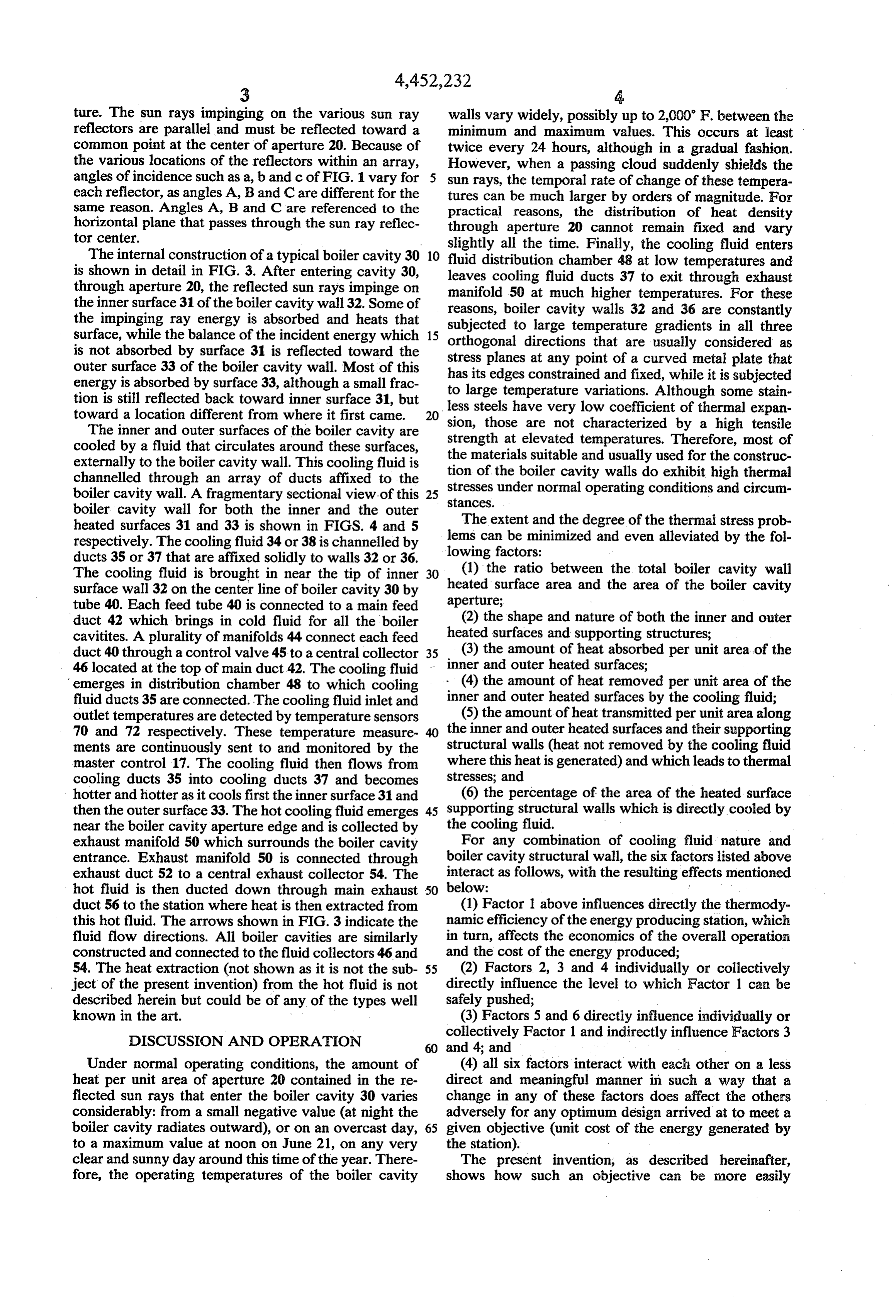
ture. The sun rays impinging on the various sun ray walls vary widely, possibly up to 2,000' F. between the reflectors are parallel and must be reflected toward a minimum and maximum values. This occurs at least common point at the center of aperture 20. Because of twice every 24 hours, although in a gradual fashion. the various locations of the reflectors within an array, However, when a passing cloud suddenly shields the angles of incidence such as a, b and c of FIG. 1 vary for sun rays, the temporal rate of change of these tempera each reflector, as angles A, B and Care different for the tures can be much larger by orders of magnitude. For same reason. Angles A, B and C are referenced to the practical reasons, the distribution of heat density horizontal plane that passes through the sun ray reflec through aperture 20 cannot remain fixed and vary tor center. slightly all the time. Finally, the cooling fluid enters The internal construction of a typical boiler cavity 30 10 fluid distribution chamber 48 at low temperatures and is shown in detail in FIG. 3. After entering cavity 30, through aperture 20, the reflected sun rays impinge on leaves cooling fluid ducts 37 to exit through exhaust manifold 50 at much higher temperatures. For these the inner surface 31 of the boiler cavity wall32. Some of reasons, boiler cavity walls 32 and 36 are constantly the impinging ray energy is absorbed and heats that subjected to large temperature gradients in all three surface, while the balance of the incident energy which 15 orthogonal directions that are usually considered as is not absorbed by surface 31 is reflected toward the outer surface 33 of the boiler cavity wall. Most of this stress planes at any point of a curved metal plate that energy is absorbed by surface 33, although a small frac to largeedges has its constrained and fixed, while it is subjected temperature variations. Although some stain tion is still reflected back toward inner surface 31, but less steels have very low coefficient of thermal expan toward a location different from where it first came.
sion, those are not characterized
The inner and outer surfaces of the boiler cavity are strength at elevated temperatures. Therefore,by a high tensile cooled by a fluid that circulates around these surfaces, the materials suitable and usually used for the construc most of externally to the boiler cavity wall. This cooling fluid is tion of the boiler cavity walls do exhibit high thermal channelled through an array of ducts affixed to the boiler cavity wall. A fragmentary sectional view of this 25 stresses stances.
under normal operating conditions and circum boiler cavity wall for both the inner and the outer The extent and the degree of the thermal stress prob heated surfaces 31 and 33 is shown in FIGS. 4 and 5 respectively. The cooling fluid 34 or 38 is channelled by lems can be minimized and even alleviated by the fol ducts 35 or 37 that are affixed solidly to walls 32 or 36. lowing factors:
The cooling fluid is brought in near the tip of inner 30 (1) the ratio between the total boiler cavity wall heated surface area and the area of the boiler cavity surface wall 32 on the center line of boiler cavity 30 by aperture;
tube 40. Each feed tube 40 is connected to a main feed duct 42 which brings in cold fluid for all the boiler (2) the shape and nature of both the inner and outer cavitites. A plurality of manifolds 44 connect each feed heated surfaces and supporting structures; duct 40 through a control valve 45 to a central collector 35 (3) the amount of heat absorbed per unit area of the 46 located at the top of main duct 42. The cooling fluid inner and outer heated surfaces;
emerges in distribution chamber 48 to which cooling . (4) the amount of heat removed per unit area of the fluid ducts 35 are connected. The cooling fluid inlet and inner and outer heated surfaces by the cooling fluid; outlet temperatures are detected by temperature sensors (5) the amount of heat transmitted per unit area along 70 and 72 respectively. These temperature measure the inner and outer heated surfaces and their supporting ments are continuously sent to and monitored by the structural walls (heat not removed by the cooling fluid master control 17. The cooling fluid then flows from where this heat is generated) and which leads to thermal cooling ducts 35 into cooling ducts 37 and becomes stresses; and hotter and hotter as it cools first the inner surface 31 and (6) the percentage of the area of the heated surface then the outer surface 33. The hot cooling fluid emerges 45 supporting structural walls which is directly cooled by near the boiler cavity aperture edge and is collected by the cooling fluid.
exhaust manifold 50 which surrounds the boiler cavity For any combination of cooling fluid nature and entrance. Exhaust manifold 50 is connected through boiler cavity structural wall, the six factors listed above exhaust duct 52 to a central exhaust collector 54. The interact as follows, with the resulting effects mentioned hot fluid is then ducted down through main exhaust 50 below:
duct 56 to the station where heat is then extracted from (1) Factor 1 above influences directly the thermody this hot fluid. The arrows shown in FIG. 3 indicate the namic efficiency of the energy producing station, which fluid flow directions. All boiler cavities are similarly in turn, affects the economics of the overall operation constructed and connected to the fluid collectors 46 and and the cost of the energy produced; 54. The heat extraction (not shown as it is not the sub 55 (2) Factors 2, 3 and 4 individually or collectively ject of the present invention) from the hot fluid is not directly influence the level to which Factor 1 can be described herein but could be of any of the types well safely pushed;
known in the art. (3) Factors 5 and 6 directly influence individually or
DISCUSSION AND OPERATION
collectively Factor 1 and indirectly influence Factors 3
Under normal operating conditions, the amount of (4) all six factors interact with each other on a less heat per unit area of aperture 20 contained in the re direct and meaningful manner in such a way that a flected sun rays that enter the boiler cavity 30 varies change in any of these factors does affect the others considerably: from a small negative value (at night the adversely for any optimum design arrived at to meet a boiler cavity radiates outward), or on an overcast day, 65 given objective (unit cost of the energy generated by to a maximum value at noon on June 21, on any very the station).
clear and sunny day around this time of the year. There The present invention, as described hereinafter, fore, the operating temperatures of the boiler cavity shows how such an objective can be more easily
Page 5
reached. To that effect, the construction of the inven It is desirable to have both heated surfaces operating tion provides: at temperatures that are not too different, as discussed (1) a high ratio of heated surfaces 31 and 33 to boiler previously. That can be easily done by using coating cavity outer volume; materials with finish textures that provide a degree of (2) the means to insure the most uniform temperature reflectivity which is maximum at the tip of the inner distribution in any direction along heated surfaces 31 heated surface, remains high but still decreases as one and 33; progresses toward the base of the inner heated surface (3) the possibility to obtain the highest temperature 31, where it connects with the base of the outer heated for the cooling fluid at its exhaust point; surface 33. Then, starting at junction X of the inner and (4) a safe and reliable operation that requires no mov 10 outer heated surfaces 31 and 33, the nature of the coat ing parts and the simplest assembling possible of as ing material changes and it is replaced by a type of fewer and simplest parts as possible; and coating that is characterized by a low reflectivity and, (5) a quick way to adjust or shut off the cooling fluid consequently, high absorptivity. Depending upon the flow into the cooling fluid ducts 35 of any boiler cavity geometry of both the inner and outer heated surfaces, in as soon as an abrupt change in the level of sun ray en 15 order to keep the amount of radiation energy absorbed ergy has taken place in the array of reflectors that oper per unit area as constant as possible from point X to near ate this specific boiler cavity. the location where the cooling fluid ducts 37 connect By necessity, the incident reflected sun rays converge with exhaust manifold 50, the degree of absorptivity of through a solid angle 8 upon the central part of the the coating can be adjusted as was previously explained boiler cavity. The cross-sectional area of that converg 20 above in the case of the coating on the inner surface. ing cone of energy flux becomes smaller and smaller as The geometries of both the inner and the outer heated it penetrates deeper and deeper into the boiler cavity, surfaces can be changed from the shapes depicted in past its aperture 20. The amount of energy per unit of FIG. 3. If deemed more appropriate and desirable, the area of any surface on which it impinges, for any given contours of both surfaces could be constructed to as incident energy flux, depends on: 25 sume the shapes shown by broken lines 60 and 62 of (1) the angle at which the reflected sun rays reach any FIG. 3. It is pertinent to point out that the way the sun point such as 0 (FIG. 3), angle of incidence of sun ray r; rays are reflected from both heated surfaces keeps the and amount of energy reradiated outside through aperture (2) the degree of sun light absorptivity (or reflectiv 20 to a minimum. The amount of heat loss from the ity) of that heated surface at point 0. 30 boiler cavities is therefore minimized. In turn, the degree of sun light reflectivity depends Another very influential construction parameter pro upon: vided by the present invention is the distribution, size (1) the nature of the surface coating on the wall of the and cross-section shape of the cooling fluid ducts 35 and boiler cavity (heated surface); 37. The amount of heat removed per unit area of the (2) the external texture of that coating; 35 inner and outer heated surfaces, for a given steady state (3) the coating operating temperature; and operating temperature, depends upon the following: (4) the angle of incidence of the sun light. (1) the physical state of the cooling fluid (liquid Therefore, the amount of incident radiative energy phase, liquid/vapor phase or vapor?/gas phase); which is either absorbed or reflected at point 0 can be (2) the velocity of the cooling fluid in the ducts; adjusted and determined, for any operating tempera (3) the geometry and size of the duct cross-sections; ture, by design and construction through the use of the and following parameters: (4) the ratio between the area of the boiler cavity wall (1) the geometry of the innerheated surface and of its that is directly in contact with the cooling fluid and the supporting structural wall, which determines the angle total area of the boiler cavity wall to be cooled. of incidence of the sun rays coming in; 45 FIGS. 4 and 5 show similar sizes, geometries and (2) the nature of the heated surface coating (basic degrees of coverage of these cooling fluid ducts for reflectivity coefficient); and both the inner and outer surface walls. It need not be so (3) the texture given to its finish, which determines and to illustrate the point, one could visualize 2 out of the amount of diffracted radiation, i.e. which is not every 3 ducts 37 being removed from wall 36, such as reflected directly along one single line as per the laws of 50 those identified as 7 and 8 in FIG. 5. Also, a collector geometrical optics, but scattered away from the theo such as that which is identified as 80 in FIG. 3 could be retical line defined above. located between the inner surface wall cooling ducts The energy that is not absorbed at point 0 by the and those on the outer surface wall, in order to provide inner surface is then reflected, either directly or with a a redistribution of the cooling fluid flow. In other certain degree of scattering, to point P located on the 55 words, the number and size of the cooling ducts on both outer heated surface 33 of the boiler cavity wall 36. The surfaces do not have to correspond. amount of energy impinging per unit area of surface 33 The efficiency of the heat transfer process between at point P for that specific sun ray that is reflected from walls 32 and 36 and the cooling fluid inside ducts 35 and point 0 is less than it is when it leaves point 0, because 37 also depends upon the differences between the sur the inner surface is convex (the reflected sun rays di face temperatures of the sides of these walls that are in verge from point 0) and because the outer heated sur contact with the cooling fluid and the cooling fluid face has a total area much larger than the inner heated temperature, inside ducts 35 and 37. if too high, these surface. This achieves two dependent things: temperature differences adversely influence the heat (1) the outer heated surface receives a more uni transfer efficiency. Therefore, it could be that, for most formly distributed energy flux; and 65 boiler cavity geometries, the lowest boiler cavity wall (2) the heat flux level received by unit area is much temperatures are at line X where the inner and outer lower than that which is received per unit of area of the surfaces connect. In such a case, the cooling fluid could inner surface. be introduced in collecting manifold 80, through inlet
Page 6
duct 90 so that the cooling fluid can flow at the same a central section of boiler cavity wall for directly time, both into the inner and outer surfaces cooling receiving the sun radiation; ducts, then exit through collectors 48 and 50 respec a peripheral section of boiler cavity wall for receiving tively. In that case, the cooling fluid flow direction indirectly the sun radiation; would be reversed inside the inner surface cooling ducts means for providing that central section surface fac 35. In addition, the amounts of cooling fluid flowing in ing the incoming radiation energy to have a high reflectivity;
each direction from collecting manifold 80 can be dif means for providing that peripheral section surface ferent and made adjustable separately through a valving facing the central section to have a high absorptiv system (not shown) inserted in ducts 52 and 62. This 10 ity;
added construction feature provides the last means means for providing the removal of the heat depos needed to optimize the boiler cavity operation, under ited on the wall of the boiler cavity by a cooling any operating conditions of the sun ray reflectors. fluid to be used elsewhere; The various embodiments of the present invention means for monitoring the cooling fluid flow to match discussed above then result in a boiler cavity construc 15 the heat removal needed to keep the temperatures tion that provides the means to realize the optimum of the boiler cavity wall equal; and design conditions and operating conditions required to means for introducing and collecting the cooling achieve: the high thermodynamic efficiency, the sim fluid at locations on the boiler cavity wall such that plicity of construction, and the maximum use of the sun 20 the temperature differences between the cooling ray energy that enters the boiler cavity. The latter is fluid and the boiler cavity wall are kept constant and close to the values required to insure maximum achieved by minimizing the the amount of reradiated efficiency of the heat transfer process that takes energy out of the boiler cavity. Although, in general, place.
the sun energy is free, the sun radiation energy collected 2. A boiler cavity according to claim 1 including an by the reflectors 10 and that enters through apertures 20 25 external system for adjusting and regulating the cooling is not. Therefore, great care must be taken neither to fluid into and out of the boiler cavity cooling ducts to lose any of it nor to squander it by not using it effec match the radiation energy amount entering the boiler tively and completely. A judicious and ideally propor cavity.
tioned combination of the construction features avail 3. A boiler cavity according to claim 2 wherein: able with these various embodiments provides the 30 means is provided to maximize the energy output of means to reach this objective. the boiler cavity, thereby minimizing the produc Having thus described my invention, I claim: tion cost of such energy;
1. A boiler cavity comprising: means is provided to maximize the operation peak means for supplying concentrated sun radiation en 35 means temperature of the working cooling fluid; and is provided to minimize the operating peak ergy inside the boiler cavity; temperature of the boiler cavity wall. means for distributing the incoming radiation energy 4. A boiler cavity according to claim 3 wherein the throughout the boiler cavity; heat loss through air convection in and out of the boiler means for depositing this incoming radiation energy cavity is minimized.
evenly on the walls of the boiler cavity; 40 5. A boiler cavity according to claim 3 wherein the means for maintaining the temperatures of the wall of degree of air ionization, and loss of heat thereby, inside the boiler cavity almost equal at all locations on the boiler cavity is minimized.
that wall;
Provenance
- Collection
- Cited prior art
- Original PDF
- patentimages.storage.googleapis.com →
- Filed
- 1982-12-17
- Pages
- 6
- Method
- pdftotext (the PDF's own text layer) + pdftoppm 300dpi page scans
- Source
- Google Patents bibliographic record
- Granted
- 1984-06-05
- Inventors
- Constant V. David
- Transcribed from
- patentimages.storage.googleapis.com →