patent · US5167218
Solar collector having absorber plate formed by spraying molten metal
1 December 1992
Page 1 — bibliographic record
United States Patent (19) 11) Patent Number: 5,167,218 Deakin 45 Date of Patent: Dec. 1, 1992 54 SOLAR COLLECTOR HAVING ABSORBER 3,129,703 4/1964 Tabor .................................. 26/446 PLATE FORMED BY SPRAYING MOLTEN 4,072,262 2/1978 Godrick et al. ..................... 228/265 METAL 4,074,406 2/1978 Boyd et al. ........ ... 165/68 X
(76) Inventor: David Deakin, 19608 Enterprise 4,534,336 8/1985 Ladriere ............ ... 126/446 Way, Gaithersburg, Md. 20879 4,579,107 4/1986 Deakin ................................ 126/443 (21) Appl. No.: 483,626 Primary Examiner-Larry Jones 22 Filed: Feb. 23, 1990 Attorney, Agent, or Firm-Cushman, Darby & Cushman
Related U.S. Application Data A solar energy collector whereby an absorber plate 60) Division of Ser. No. 250,722, Sep. 29, 1988. Pat. No. thereof is formed by providing a thin metallic foil for 4,911,353, which is a continuation of Ser. No. 87,201, supporting sprayed molten metal, arranging fluid carry Aug. 20, 1987, abandoned, which is a continuation of ing tubes on the foil, and spraying molten metal using a
source of pressurized inert gas onto a substrate and (51) Int. Cl. ................................................. F24J 2/00 tubes to build up a coating of sufficient thickness to 52) U.S. Cl. .................................... 126/569; 126/661; form a unified solar collector panel comprising the 126/663; 126/908; 126/654 absorber plate, embedded tube and foil which have (58) Field of Search ........................ 126/417, 446, 443 good thermal contact with each other. The method (56) References Cited further includes forming a selective surface on the
sprayed metal absorber plate.
966,070 8/1910 Bailey .................... as . . . . . . . . . . 126/446 17 Claims, 3 Drawing Sheets
Page 2
Drawing sheet — no readable text.
Page 3
Zezzzzzzie - Zaragon. A 7. A
SK. 444 saazagazraaaa.
ma suava a wa wa una sua at va a via is a has
anySYNNNNNNaNNYaS
On Saty warran unwaymany sma was saw
Page 4
Drawing sheet — no readable text.
Page 5
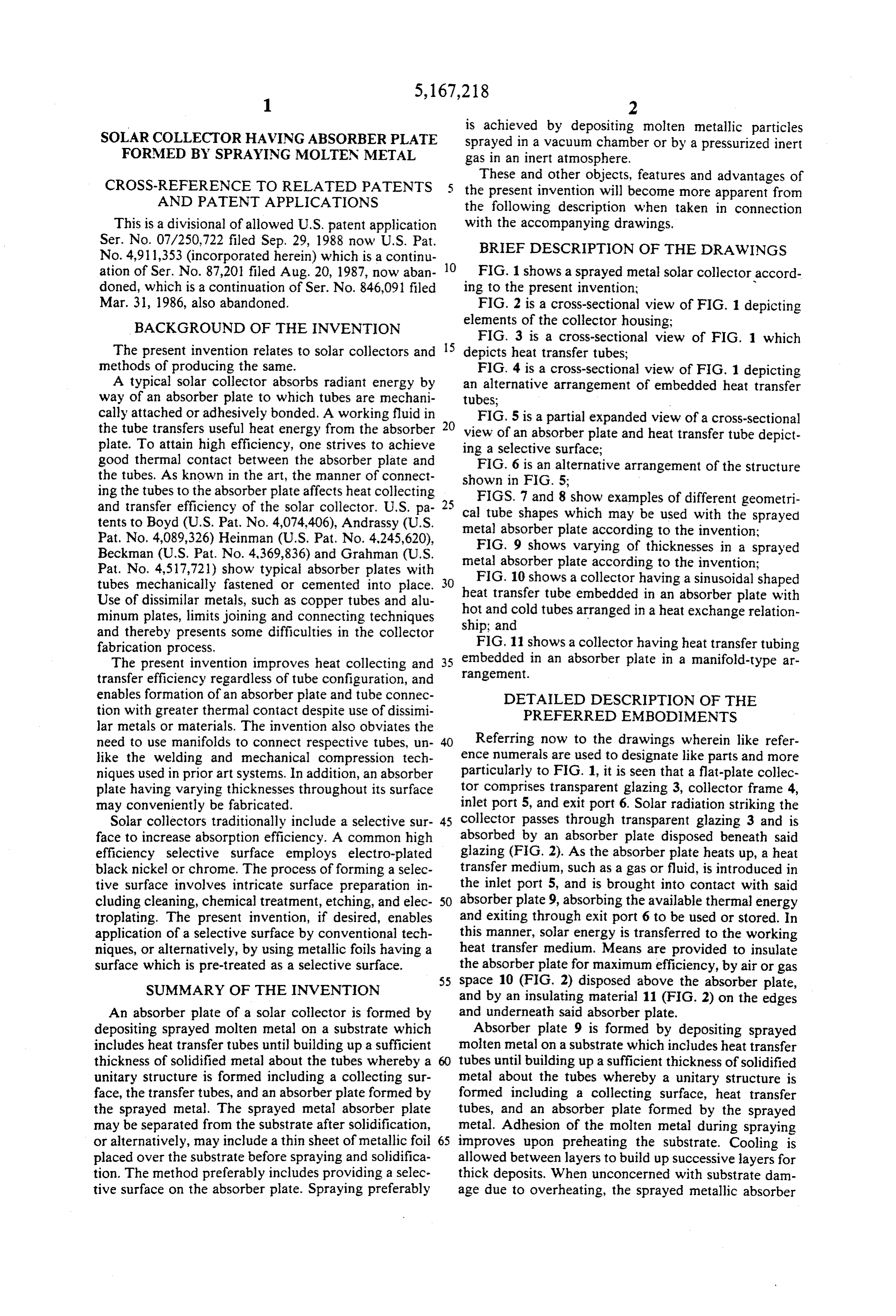
is achieved by depositing molten metallic particles
SOLAR COLLECTOR HAVING ABSORBER PLATE sprayed in a vacuum chamber or by a pressurized inert FORMED BY SPRAYING MOLTEN METAL gas in an inert atmosphere.
These and other objects, features and advantages of
CROSS-REFERENCE TO RELATED PATENTS 5 the present invention will become more apparent from AND PATENT APPLICATIONS the following description when taken in connection This is a divisional of allowed U.S. patent application with the accompanying drawings.
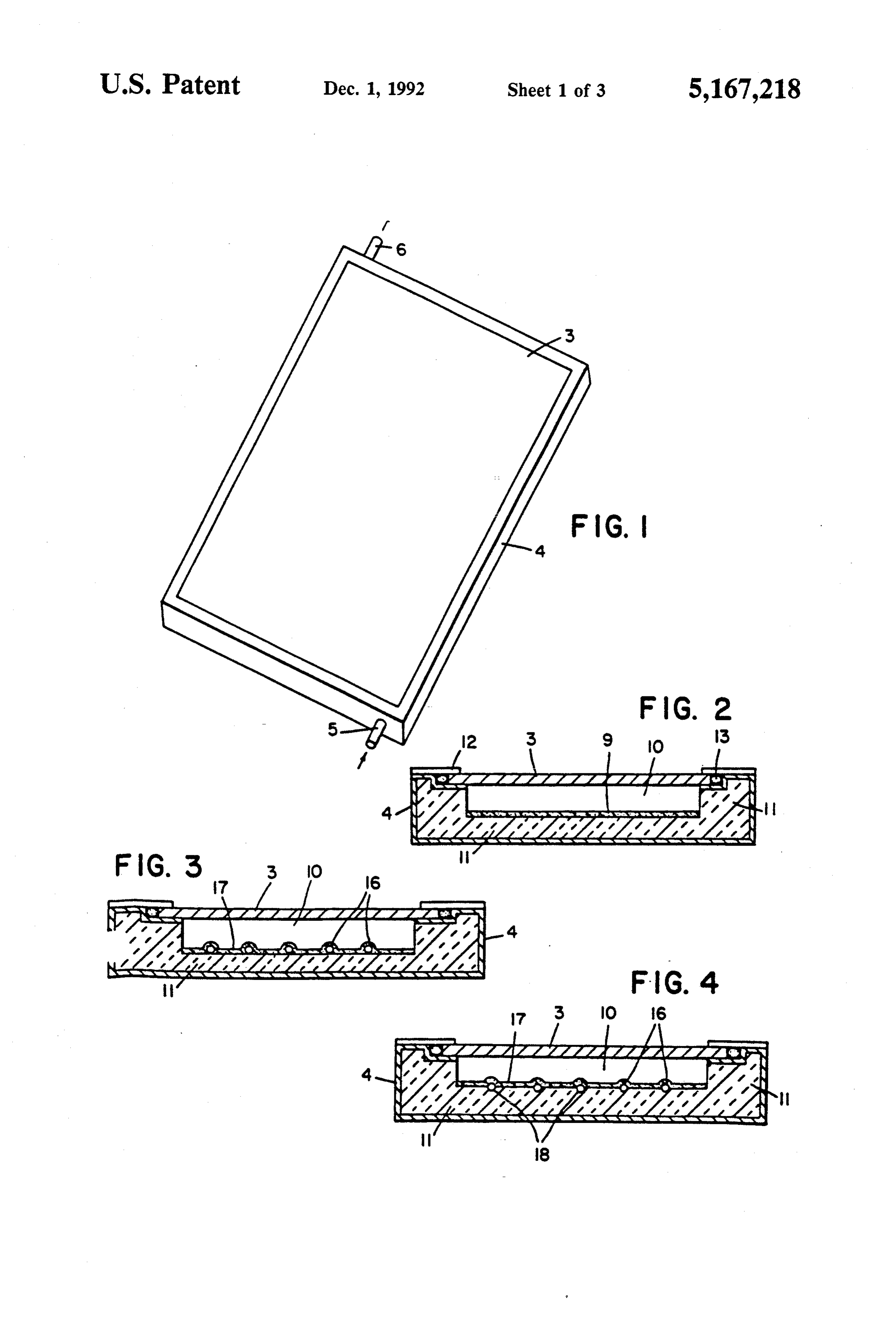
No. 4,911,353 (incorporated herein) which is a continu 10 BRIEF DESCRIPTION OF THE DRAWINGS ation of Ser. No. 87,201 filed Aug. 20, 1987, now aban FIG. 1 shows a sprayed metal solar collector accord doned, which is a continuation of Ser. No. 846,091 filed ing to the present invention; - Mar. 31, 1986, also abandoned. FIG. 2 is a cross-sectional view of FIG. 1 depicting BACKGROUND OF THE INVENTION elements of the collector housing:
FIG. 3 is a cross-sectional view of FIG. 1 which
The present invention relates to solar collectors and 5 depicts heat transfer tubes;
methods of producing the same. FIG. 4 is a cross-sectional view of FIG. 1 depicting A typical solar collector absorbs radiant energy by an alternative arrangement of embedded heat transfer way of an absorber plate to which tubes are mechani tubes;
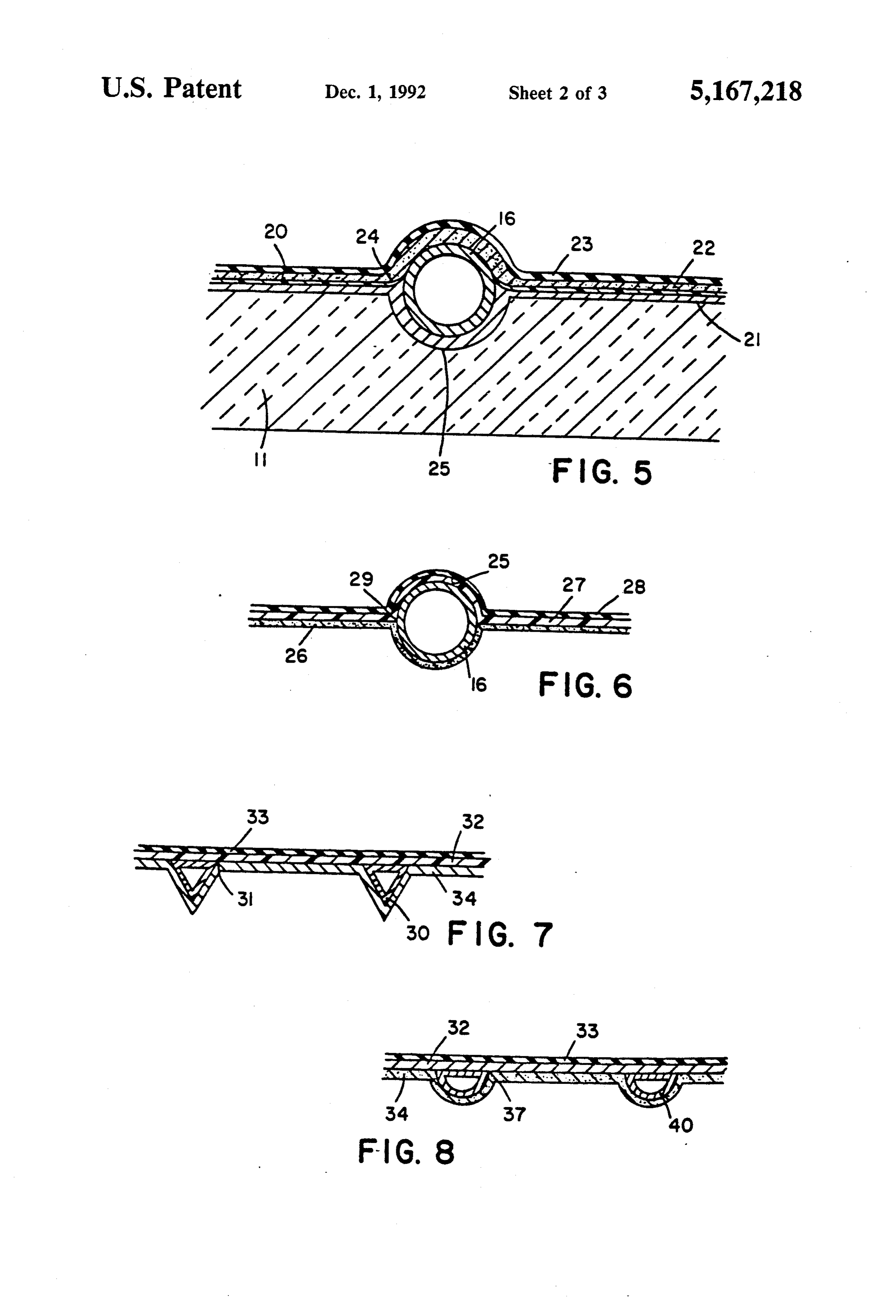
cally attached or adhesively bonded. A working fluid in FIG. 5 is a partial expanded view of a cross-sectional the tube transfers useful heat energy from the absorber 20 view of an absorber plate and heat transfer tube depict plate. To attain high efficiency, one strives to achieve ing a selective surface;
good thermal contact between the absorber plate and FIG. 6 is an alternative arrangement of the structure the tubes. As known in the art, the manner of connect shown in FIG. 5;
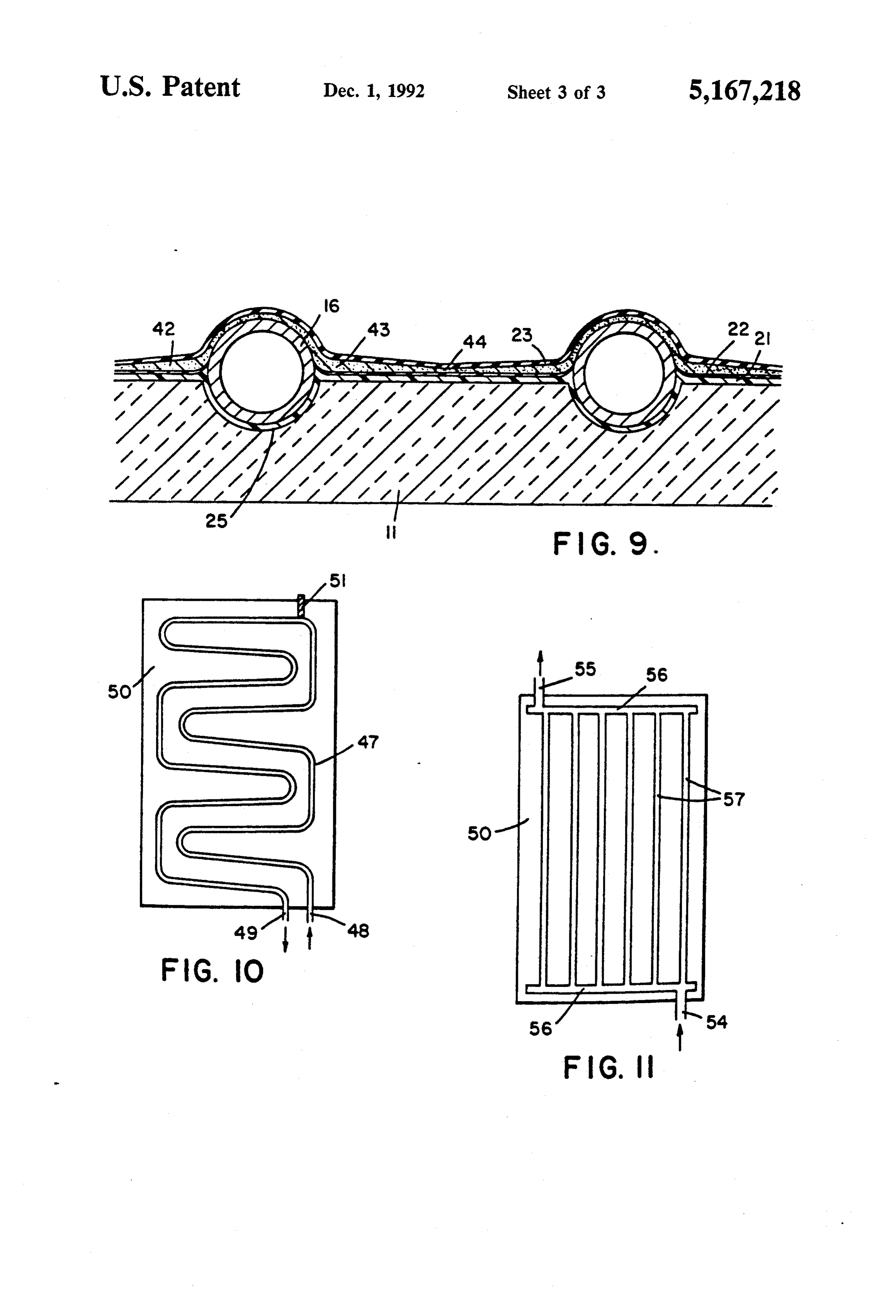
ing the tubes to the absorber plate affects heat collecting FIGS. 7 and 8 show examples of different geometri and transfer efficiency of the solar collector. U.S. pa cal tube shapes which may be used with the sprayed tents to Boyd (U.S. Pat. No. 4,074,406), Andrassy (U.S. metal absorber plate according to the invention; Pat. No. 4,089,326) Heinman (U.S. Pat. No. 4.245,620), FIG. 9 shows varying of thicknesses in a sprayed Beckman (U.S. Pat. No. 4,369,836) and Grahman (U.S. metal absorber plate according to the invention; Pat. No. 4,517,721) show typical absorber plates with tubes mechanically fastened or cemented into place. 30 heatFIG. 10 shows a collector having a sinusoidal shaped transfer tube embedded in an absorber plate with
Use of dissimilar metals, such as copper tubes and alu hot and minum plates, limits joining and connecting techniques ship; andcold tubes arranged in a heat exchange relation and thereby presents some difficulties in the collector FIG. 11 shows a collector having heat transfer tubing fabrication process.
embedded in an absorber plate in a manifold-type ar
The present invention improves heat collecting and 35 rangement.
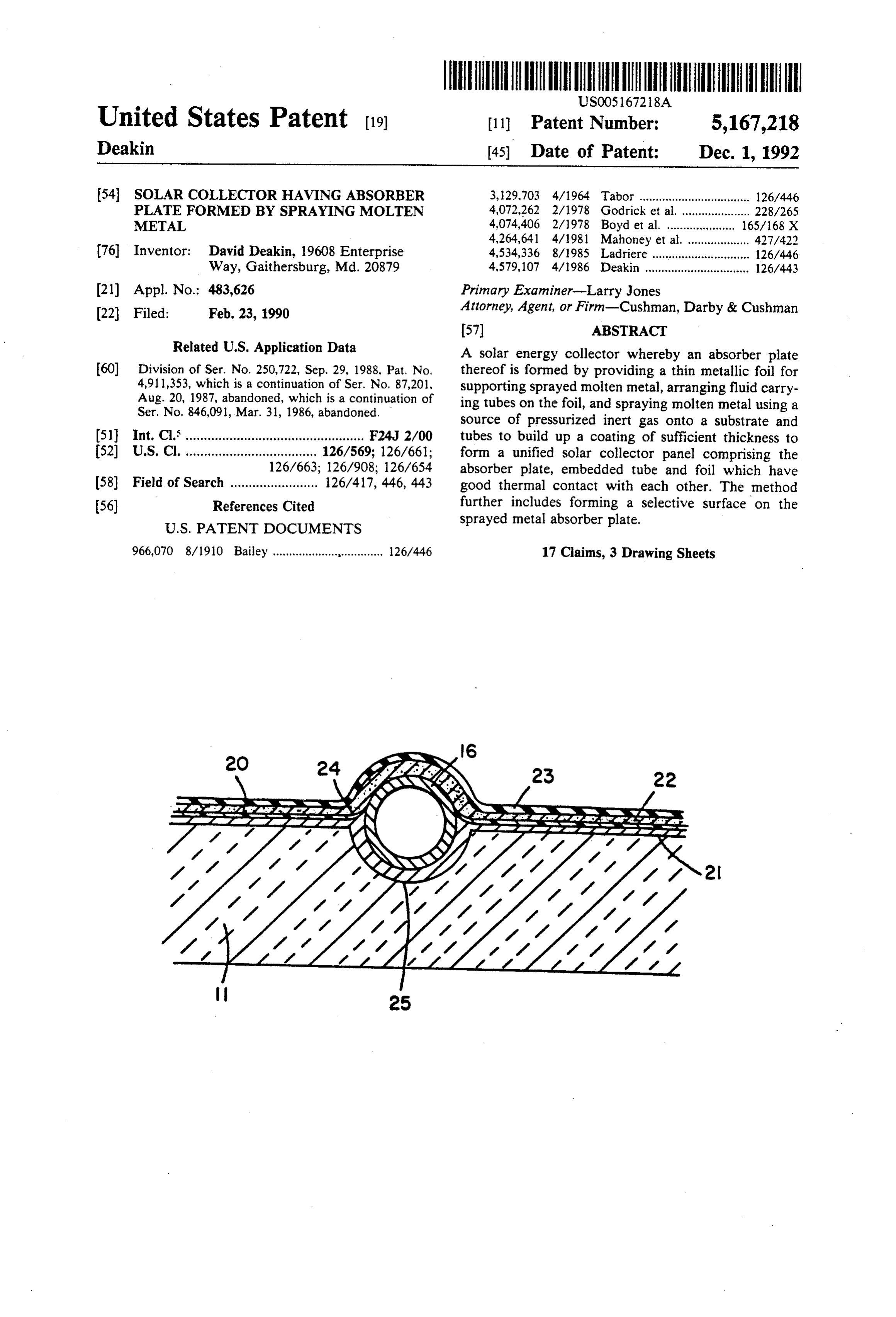
transfer efficiency regardless of tube configuration, and enables formation of an absorber plate and tube connec DETAILED DESCRIPTION OF THE tion with greater thermal contact despite use of dissimi PREFERRED EMBODIMENTS lar metals or materials. The invention also obviates the need to use manifolds to connect respective tubes, un Referring now to the drawings wherein like refer like the welding and mechanical compression tech ence numerals are used to designate like parts and more niques used in prior art systems. In addition, an absorber particularly to FIG. 1, it is seen that a flat-plate collec plate having varying thicknesses throughout its surface tor comprises transparent glazing 3, collector frame 4, may conveniently be fabricated. inlet port 5, and exit port 6. Solar radiation striking the Solar collectors traditionally include a selective sur 45 collector passes through transparent glazing 3 and is face to increase absorption efficiency. A common high absorbed by an absorber plate disposed beneath said efficiency selective surface employs electro-plated glazing (FIG. 2). As the absorber plate heats up, a heat black nickel or chrome. The process of forming a selec transfer medium, such as a gas or fluid, is introduced in tive surface involves intricate surface preparation in the inlet port 5, and is brought into contact with said cluding cleaning, chemical treatment, etching, and elec 50 absorber plate 9, absorbing the available thermal energy troplating. The present invention, if desired, enables and exiting through exit port 6 to be used or stored. In application of a selective surface by conventional tech this manner, solar energy is transferred to the working niques, or alternatively, by using metallic foils having a heat transfer medium. Means are provided to insulate surface which is pre-treated as a selective surface. the absorber plate for maximum efficiency, by air or gas 55 space 10 (FIG. 2) disposed above the absorber plate,
SUMMARY OF THE INVENTION and by an insulating material 11 (FIG. 2) on the edges An absorber plate of a solar collector is formed by and underneath said absorber plate.
depositing sprayed molten metal on a substrate which Absorber plate 9 is formed by depositing sprayed includes heat transfer tubes until building up a sufficient molten metal on a substrate which includes heat transfer thickness of solidified metal about the tubes whereby a tubes until building up a sufficient thickness of solidified unitary structure is formed including a collecting Sur metal about the tubes whereby a unitary structure is face, the transfer tubes, and an absorber plate formed by formed including a collecting surface, heat transfer the sprayed metal. The sprayed metal absorber plate tubes, and an absorber plate formed by the sprayed may be separated from the substrate after solidification, metal. Adhesion of the molten metal during spraying or alternatively, may include a thin sheet of metallic foil 65 improves upon preheating the substrate. Cooling is placed over the substrate before spraying and solidifica allowed between layers to build up successive layers for tion. The method preferably includes providing a Selec thick deposits. When unconcerned with substrate dam tive surface on the absorber plate. Spraying preferably age due to overheating, the sprayed metallic absorber
Page 6
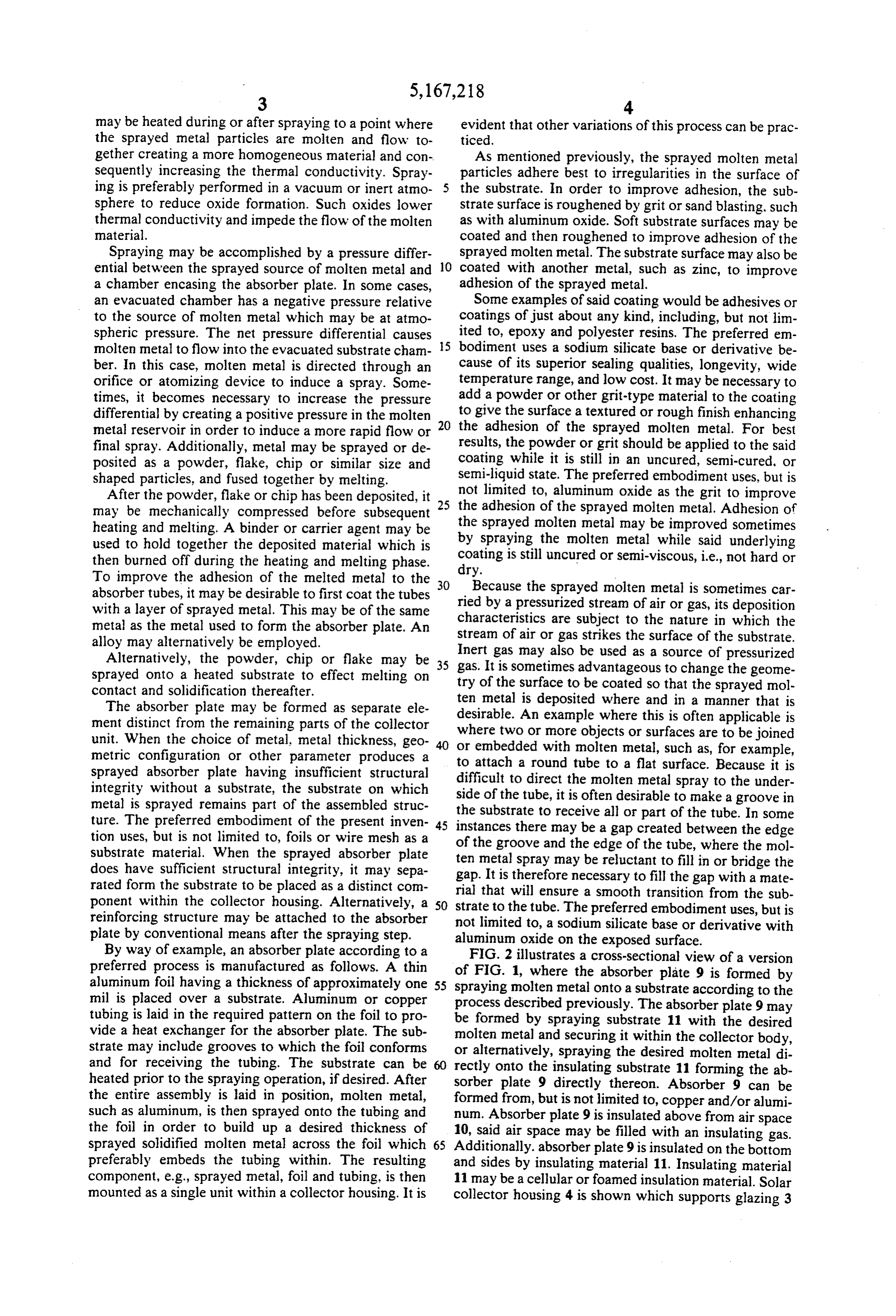
may be heated during or after spraying to a point where evident that other variations of this process can be prac the sprayed metal particles are molten and flow to ticed.
gether creating a more homogeneous material and con As mentioned previously, the sprayed molten metal sequently increasing the thermal conductivity. Spray particles adhere best to irregularities in the surface of ing is preferably performed in a vacuum or inert atmo the substrate. In order to improve adhesion, the sub sphere to reduce oxide formation. Such oxides lower strate surface is roughened by grit or sand blasting, such thermal conductivity and impede the flow of the molten as with aluminum oxide. Soft substrate surfaces may be material. coated and then roughened to improve adhesion of the Spraying may be accomplished by a pressure differ sprayed molten metal. The substrate surface may also be ential between the sprayed source of molten metal and 10 coated with another metal, such as zinc, to improve a chamber encasing the absorber plate. In some cases, adhesion of the sprayed metal.
an evacuated chamber has a negative pressure relative Some examples of said coating would be adhesives or to the source of molten metal which may be at atmo coatings of just about any kind, including, but not lim spheric pressure. The net pressure differential causes 15 ited to, epoxy and polyester resins. The preferred em molten metal to flow into the evacuated substrate cham bodiment uses a sodium silicate base or derivative be ber. In this case, molten metal is directed through an cause of its superior sealing qualities, longevity, wide orifice or atomizing device to induce a spray. Some temperature range, and low cost. It may be necessary to times, it becomes necessary to increase the pressure add a powder or other grit-type material to the coating differential by creating a positive pressure in the molten 20 to give the surface a textured or rough finish enhancing metal reservoir in order to induce a more rapid flow or the adhesion of the sprayed molten metal. For best final spray. Additionally, metal may be sprayed or de results, the powder or grit should be applied to the said posited as a powder, flake, chip or similar size and coating while it is still in an uncured, semi-cured, or shaped particles, and fused together by melting. semi-liquid state. The preferred embodiment uses, but is After the powder, flake or chip has been deposited, it not limited to, aluminum oxide as the grit to improve may be mechanically compressed before subsequent 25 the adhesion of the sprayed molten metal. Adhesion of heating and melting. A binder or carrier agent may be the sprayed molten metal may be improved sometimes used to hold together the deposited material which is by spraying the molten metal while said underlying then burned off during the heating and melting phase. coating dry.
is still uncured or semi-viscous, i.e., not hard or
To improve the adhesion of the melted metal to the absorber tubes, it may be desirable to first coat the tubes riedBecause the sprayed molten metal is sometimes car by a pressurized stream of air or gas, its deposition with a layer of sprayed metal. This may be of the same characteristics metal as the metal used to form the absorber plate. An stream of air orare subject to the nature in which the gas strikes the surface of the substrate.
alloy may alternatively be employed.
Alternatively, the powder, chip or flake may be 35 gas. Inert gas may also be used as a source of pressurized sprayed onto a heated substrate to effect melting on try ofIt the is sometimes advantageous to change the geome surface to be coated so that the sprayed mol contact and solidification thereafter.
ten
The absorber plate may be formed as separate ele desirable. An metal is deposited where and in a manner that is ment distinct from the remaining parts of the collector where two or example more where this is often applicable is objects or surfaces are to be joined unit. When the choice of metal, metal thickness, geo 40 or embedded with molten metal, such as, for example, metric configuration or other parameter produces a to attach a round tube to a flat surface.
sprayed absorber plate having insufficient structural difficult to direct the molten metal spray toBecause the
under integrity without a substrate, the substrate on which metal is sprayed remains part of the assembled struc side of the tube, it is often desirable to make a groove in ture. The preferred embodiment of the present inven 45 instances theretomay the substrate receive all or part of the tube. In some tion uses, but is not limited to, foils or wire mesh as a of the groove and thebeedge a gap created between the edge of the tube, where the mol substrate material. When the sprayed absorber plate ten metal spray may be reluctant does have sufficient structural integrity, it may sepa gap. It is therefore necessary to filltothe fill in or bridge the gap with a mate rated form the substrate to be placed as a distinct com rial that will ensure a smooth transition from the sub ponent within the collector housing. Alternatively, a 50 strate to the tube. The preferred embodiment uses, but is reinforcing structure may be attached to the absorber not limited to, a sodium silicate base or derivative with plate by conventional means after the spraying step. aluminum oxide on the exposed surface. By way of example, an absorber plate according to a FIG. 2 illustrates a cross-sectional view of a version preferred process is manufactured as follows. A thin of FIG. 1, where the absorber plate 9 is formed by aluminum foil having a thickness of approximately one 55 spraying molten metal onto a substrate according to the mil is placed over a substrate. Aluminum or copper process described previously. The absorber plate 9 may tubing is laid in the required pattern on the foil to pro be formed by spraying substrate 11 with the desired vide a heat exchanger for the absorber plate. The sub molten metal and securing it within the collector body, strate may include grooves to which the foil conforms or alternatively, spraying the desired molten metal di and for receiving the tubing. The substrate can be rectly onto the insulating substrate 11 forming the ab heated prior to the spraying operation, if desired. After sorber plate 9 directly thereon. Absorber 9 can be the entire assembly is laid in position, molten metal, formed from, but is not limited to, copper and/or alumi such as aluminum, is then sprayed onto the tubing and num. Absorber plate 9 is insulated above from air space the foil in order to build up a desired thickness of 10, said air space may be filled with an insulating gas. sprayed solidified molten metal across the foil which 65 Additionally. absorber plate 9 is insulated on the bottom preferably embeds the tubing within. The resulting and sides by insulating material 11. Insulating material component, e.g., sprayed metal, foil and tubing, is then 11 may be a cellular or foamed insulation material. Solar mounted as a single unit within a collector housing. It is collector housing 4 is shown which supports glazing 3
Page 7
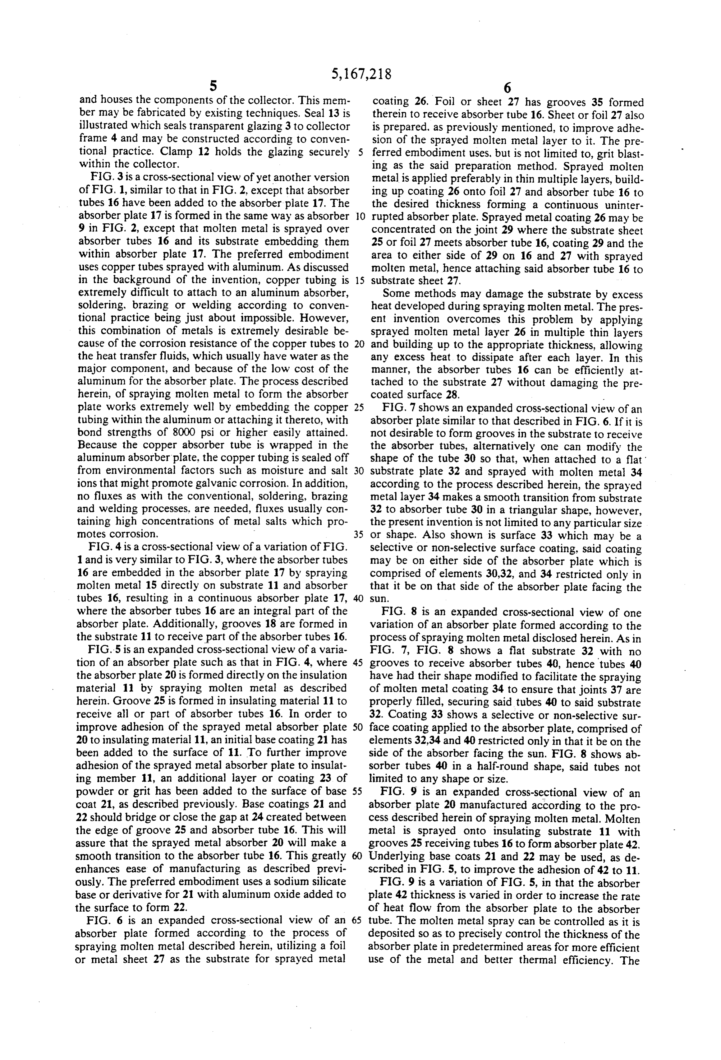
and houses the components of the collector. This mem coating 26. Foil or sheet 27 has grooves 35 formed ber may be fabricated by existing techniques. Seal 13 is therein to receive absorber tube 16. Sheet or foil 27 also illustrated which seals transparent glazing 3 to collector is prepared, as previously mentioned, to improve adhe frame 4 and may be constructed according to conven sion of the sprayed molten metal layer to it. The pre tional practice. Clamp 12 holds the glazing securely ferred embodiment uses, but is not limited to, grit blast within the collector. ing as the said preparation method. Sprayed molten FIG. 3 is a cross-sectional view of yet another version metal is applied preferably in thin multiple layers, build of FIG, 1, similar to that in FIG. 2, except that absorber ing up coating 26 onto foil 27 and absorber tube 16 to tubes 16 have been added to the absorber plate 17. The the desired thickness forming a continuous uninter absorber plate 17 is formed in the same way as absorber O rupted absorber plate. Sprayed metal coating 26 may be 9 in FIG. 2, except that molten metal is sprayed over concentrated on the joint 29 where the substrate sheet absorber tubes 16 and its substrate embedding them 25 or foil 27 meets absorber tube 16, coating 29 and the within absorber plate 17. The preferred embodiment area to either side of 29 on 16 and 27 with sprayed uses copper tubes sprayed with aluminum. As discussed molten metal, hence attaching said absorber tube 16 to in the background of the invention, copper tubing is 15 substrate sheet 27.
extremely difficult to attach to an aluminum absorber, Some methods may damage the substrate by excess soldering, brazing or welding according to conven heat developed during spraying molten metal. The pres tional practice being just about impossible. However, ent invention overcomes this problem by applying this combination of metals is extremely desirable be sprayed molten metal layer 26 in multiple thin layers cause of the corrosion resistance of the copper tubes to 20 and building up to the appropriate thickness, allowing the heat transfer fluids, which usually have water as the any excess heat to dissipate after each layer. In this major component, and because of the low cost of the manner, the absorber tubes 16 can be efficiently at aluminum for the absorber plate. The process described tached to the substrate 27 without damaging the pre herein, of spraying molten metal to form the absorber coated surface 28.
plate works extremely well by embedding the copper 25 FIG. 7 shows an expanded cross-sectional view of an tubing within the aluminum or attaching it thereto, with absorber plate similar to that described in FIG. 6. If it is bond strengths of 8000 psi or higher easily attained. not desirable to form grooves in the substrate to receive Because the copper absorber tube is wrapped in the the absorber tubes, alternatively one can modify the aluminum absorber plate, the copper tubing is sealed off shape of the tube 30 so that, when attached to a flat from environmental factors such as moisture and salt 30 substrate plate 32 and sprayed with molten metal 34 ions that might promote galvanic corrosion. In addition, according to the process described herein, the sprayed no fluxes as with the conventional, soldering, brazing metal layer 34 makes a smooth transition from substrate and welding processes, are needed, fluxes usually con 32 to absorber tube 30 in a triangular shape, however, taining high concentrations of metal salts which pro the present invention is not limited to any particular size motes corrosion. - 35 or shape. Also shown is surface 33 which may be a FIG. 4 is a cross-sectional view of a variation of FIG. selective or non-selective surface coating, said coating 1 and is very similar to FIG. 3, where the absorber tubes may be on either side of the absorber plate which is 16 are embedded in the absorber plate 17 by spraying comprised of elements 30,32, and 34 restricted only in molten metal 15 directly on substrate 11 and absorber that it be on that side of the absorber plate facing the tubes 16, resulting in a continuous absorber plate 17, 40 S.
where the absorber tubes 16 are an integral part of the FIG. 8 is an expanded cross-sectional view of one absorber plate. Additionally, grooves 18 are formed in variation of an absorber plate formed according to the the substrate 11 to receive part of the absorber tubes 16. process of spraying molten metal disclosed herein. As in FIG.5 is an expanded cross-sectional view of a varia FIG. 7, FIG. 8 shows a flat substrate 32 with no tion of an absorber plate such as that in FIG. 4, where 45 grooves to receive absorber tubes 40, hence tubes 40 the absorber plate 20 is formed directly on the insulation have had their shape modified to facilitate the spraying material 11 by spraying molten metal as described of molten metal coating 34 to ensure that joints 37 are herein. Groove 25 is formed in insulating material 11 to properly filled, securing said tubes 40 to said substrate receive all or part of absorber tubes 16. In order to 32. Coating 33 shows a selective or non-selective sur improve adhesion of the sprayed metal absorber plate 50 face coating applied to the absorber plate, comprised of 20 to insulating material 11, an initial base coating 21 has elements 32,34 and 40 restricted only in that it be on the been added to the surface of 11. To further improve side of the absorber facing the sun. FIG. 8 shows ab adhesion of the sprayed metal absorber plate to insulat sorber tubes 40 in a half-round shape, said tubes not ing member 11, an additional layer or coating 23 of limited to any shape or size.
powder or grit has been added to the surface of base 55 FIG. 9 is an expanded cross-sectional view of an coat 21, as described previously. Base coatings 21 and absorber plate 20 manufactured according to the pro 22 should bridge or close the gap at 24 created between cess described herein of spraying molten metal. Molten the edge of groove 25 and absorber tube 16. This will metal is sprayed onto insulating substrate 11 with assure that the sprayed metal absorber 20 will make a grooves 25 receiving tubes 16 to form absorber plate 42. smooth transition to the absorber tube 16. This greatly 60 Underlying base coats 21 and 22 may be used, as de enhances ease of manufacturing as described previ scribed in FIG. 5, to improve the adhesion of 42 to 11. ously. The preferred embodiment uses a sodium silicate FIG. 9 is a variation of FIG. 5, in that the absorber base or derivative for 21 with aluminum oxide added to plate 42 thickness is varied in order to increase the rate the surface to form 22. of heat flow from the absorber plate to the absorber FIG. 6 is an expanded cross-sectional view of an 65 tube. The molten metal spray can be controlled as it is absorber plate formed according to the process of deposited so as to precisely control the thickness of the spraying molten metal described herein, utilizing a foil absorber plate in predetermined areas for more efficient or metal sheet 27 as the substrate for sprayed metal use of the metal and better thermal efficiency. The
Page 8
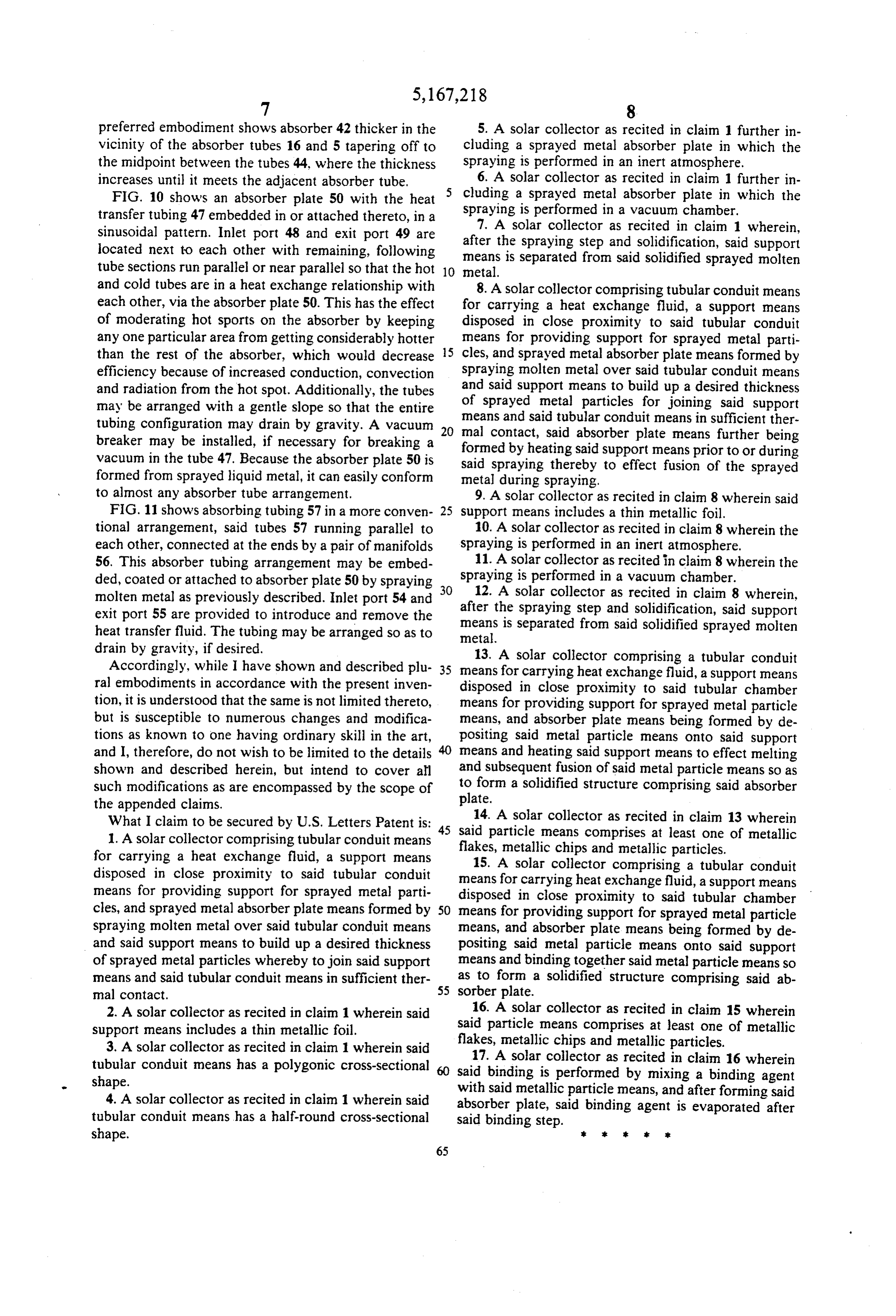
preferred embodiment shows absorber 42 thicker in the 5. A solar collector as recited in claim 1 further in vicinity of the absorber tubes 16 and 5 tapering off to cluding a sprayed metal absorber plate in which the the midpoint between the tubes 44, where the thickness spraying is performed in an inert atmosphere. increases until it meets the adjacent absorber tube, 6. A solar collector as recited in claim 1 further in FIG. 10 shows an absorber plate 50 with the heat cluding a sprayed metal absorber plate in which the transfer tubing 47 embedded in or attached thereto, in a spraying is performed in a vacuum chamber. sinusoidal pattern. Inlet port 48 and exit port 49 are after 7. A solar collector as recited in claim 1 wherein, located next to each other with remaining, following meansthe is spraying step and solidification, said support separated from said solidified sprayed molten tube sections run parallel or near parallel so that the hot 10 metal.
and cold tubes are in a heat exchange relationship with 8. A solar collector comprising tubular conduit means each other, via the absorber plate 50. This has the effect for carrying a heat exchange fluid, a support means of moderating hot sports on the absorber by keeping disposed in close proximity to said tubular conduit any one particular area from getting considerably hotter means for providing support for sprayed metal parti than the rest of the absorber, which would decrease 5 cles, and sprayed metal absorber plate means formed by efficiency because of increased conduction, convection spraying molten metal over said tubular conduit means and radiation from the hot spot. Additionally, the tubes and said support means to build up a desired thickness may be arranged with a gentle slope so that the entire of sprayed metal particles for joining said support tubing configuration may drain by gravity. A vacuum 20 means and said tubular conduit means in sufficient ther breaker may be installed, if necessary for breaking a formed mal contact, said absorber plate means further being by heating said support means prior to or during vacuum in the tube 47. Because the absorber plate 50 is said spraying thereby to effect fusion of the sprayed formed from sprayed liquid metal, it can easily conform metal during spraying.
to almost any absorber tube arrangement, 9. A solar collector as recited in claim 8 wherein said FIG. 11 shows absorbing tubing 57 in a more conven 25 support means includes a thin metallic foil. tional arrangement, said tubes 57 running parallel to 10. A solar collector as recited in claim 8 wherein the each other, connected at the ends by a pair of manifolds spraying is performed in an inert atmosphere. 56. This absorber tubing arrangement may be embed 11. A solar collector as recited in claim 8 wherein the ded, coated or attached to absorber plate 50 by spraying 30 spraying is performed in a vacuum chamber. molten metal as previously described. Inlet port 54 and 12. A solar collector as recited in claim 8 wherein, exit port 55 are provided to introduce and remove the after the spraying step and solidification, said support heat transfer fluid. The tubing may be arranged so as to metal. is separated from said solidified sprayed molten means drain by gravity, if desired. 13. A solar collector comprising a tubular conduit Accordingly, while I have shown and described plu 35 means for carrying heat exchange fluid, a support means ral embodiments in accordance with the present inven disposed in close proximity to said tubular chamber tion, it is understood that the same is not limited thereto, means for providing support for sprayed metal particle but is susceptible to numerous changes and modifica means, and absorber plate means being formed by de tions as known to one having ordinary skill in the art, positing said metal particle means onto said support and I, therefore, do not wish to be limited to the details 40 means and heating said support means to effect melting shown and described herein, but intend to cover all and subsequent fusion of said metal particle means so as such modifications as are encompassed by the scope of to form a solidified structure comprising said absorber plate.
the appended claims.
What I claim to be secured by U.S. Letters Patent is: 45 said14.particle
A solar collector as recited in claim 13 wherein 1. A solar collector comprising tubular conduit means flakes, metallicmeans chips comprises at least one of metallic and metallic particles.
for carrying a heat exchange fluid, a support means 15. A solar collector comprising a tubular conduit disposed in close proximity to said tubular conduit means for carrying heat exchange fluid, a support means means for providing support for sprayed metal parti disposed in close proximity to said tubular chamber cles, and sprayed metal absorber plate means formed by 50 means for providing support for sprayed metal particle spraying molten metal over said tubular conduit means means, and absorber plate means being formed by de and said support means to build up a desired thickness positing said metal particle means onto said support of sprayed metal particles whereby to join said support means and binding together said metal particle means so means and said tubular conduit means in sufficient ther as to form a solidified structure comprising said ab mal contact. 55 sorber plate.
2. A solar collector as recited in claim 1 wherein said 16. A solar collector as recited in claim 15 wherein support means includes a thin metallic foil. said particle means comprises at least one of metallic 3. A solar collector as recited in claim 1 wherein said flakes, metallic chips and metallic particles. tubular conduit means has a polygonic cross-sectional 17. A solar collector as recited in claim 16 wherein shape. said binding is performed by mixing a binding agent 4. A solar collector as recited in claim 1 wherein said with said metallic particle means, and after forming said absorber plate, said binding agent is evaporated after tubular conduit means has a half-round cross-sectional said binding step.
shape. k
Provenance
- Collection
- Cited prior art
- Original PDF
- patentimages.storage.googleapis.com →
- Filed
- 1990-02-23
- Pages
- 8
- Method
- pdftotext (the PDF's own text layer) + pdftoppm 300dpi page scans
- Source
- Google Patents bibliographic record
- Granted
- 1992-12-01
- Inventors
- David Deakin
- Transcribed from
- patentimages.storage.googleapis.com →