patent · US4479485A
Power efficiency for very high temperature solar thermal cavity receivers
30 October 1984
Page 1
United States Patent (19)
McDougal et al.
54 POWER EFFICIENCY FOR VERY HIGH
TEMPERATURE SOLARTHERMAL CAVITY
RECEIVERS
75 Inventors: Allan R. McDougal,
LaCanada-Flintridge; Robert R.
Hale, Upland, both of Calif.
(73) Assignee: The United States of America as represented by the United States
Department of Energy, Washington,
51) Int, C. ................................................. F24J 3/02 52) U.S. C. ..................................... 126/439; 126/441
1969,839 8/1934 Goddard ............................. 126/439 2,741,691 4/1956 Lee ............. ... 126/439 3,490,950 1/1970 Myer ..................................... 136/89
4,090,498 5/1978 Benson ................................ 126/425 4,125,109 11/1978 Erwin .................................. 126/451
4,64,123 8/1979 Smith .............................. 126/438 X 4,198.953 4/1980 Power ... . 126/439 X 4,402,306 9/1983 McElroy ............................. 126/439
FOREIGN PATENT DOCUMENTS
472427 6/1952 Italy .................. vo so a ... 126/438 162362 12/1981 Japan ................................... 126/438
OTHER PUBLICATIONS
"Baffle Keeps Solar Energy in Receiver", p. 27 of NASA Tech. Briefs, Spring 1981.
Primary Examiner-Margaret A. Focarino
Attorney, Agent, or Firm-Michael F. Esposito
This invention is an improved solar energy cavity re ceiver for exposing materials and components to high temperatures. The receiver includes a housing having an internal reflective surface defining a cavity and hav ing an inlet for admitting solar radiation thereto. A photothermal absorber is positioned in the cavity to receive radiation from the inlet. A reflective baffle is positioned between the absorber and the inlet to se verely restrict the re-radiation of energy through the inlet. The front surface of the baffle defines a narrow annulus with the internal reflective surface of the hous ing. The front surface of the baffle is contoured to re flect incoming radiation onto the internal surface of the housing, from which it is reflected through the annulus and onto the front surface of the absorber. The back surface of the baffle intercepts infrared radiation from the front of the absorber. With this arrangement, a high percentage of the solar power input is retained in the cavity; thus, high internal temperatures are attained. 9 Claims, 2 Drawing Figures
Page 2
Drawing sheet — no readable text.
Page 3
Drawing sheet — no readable text.
Page 4
the above-mentioned internal surface, an annulus ex
POWER EFFICIENCY FORVERY HIGH tending about the axis of the receiver. The reflective TEMPERATURE SOLAR THERMAL CAVITY front surface is contoured to receive solar radiation RECEIVERS from the inlet and to reflect the same to the absorber through said annulus via secondary reflection from the
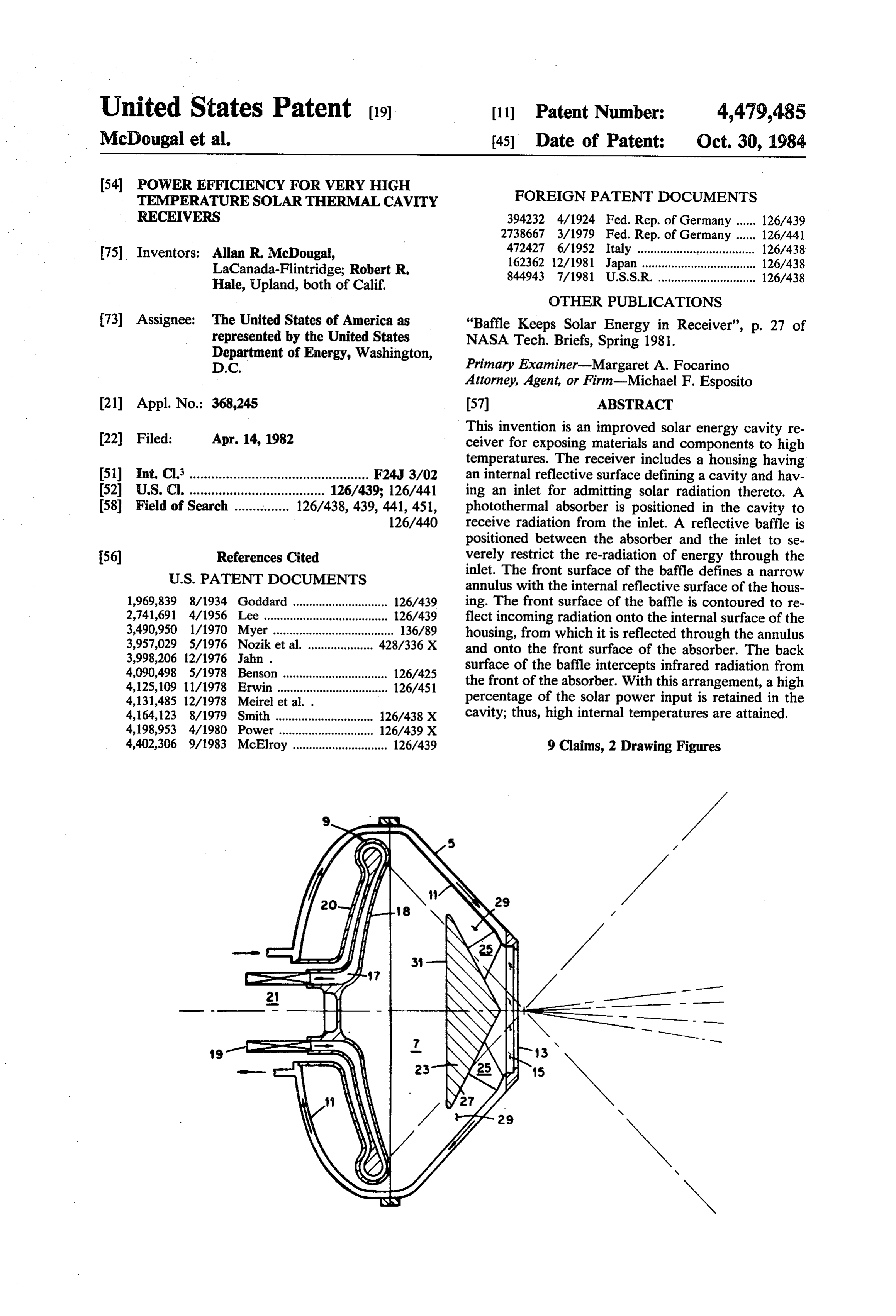
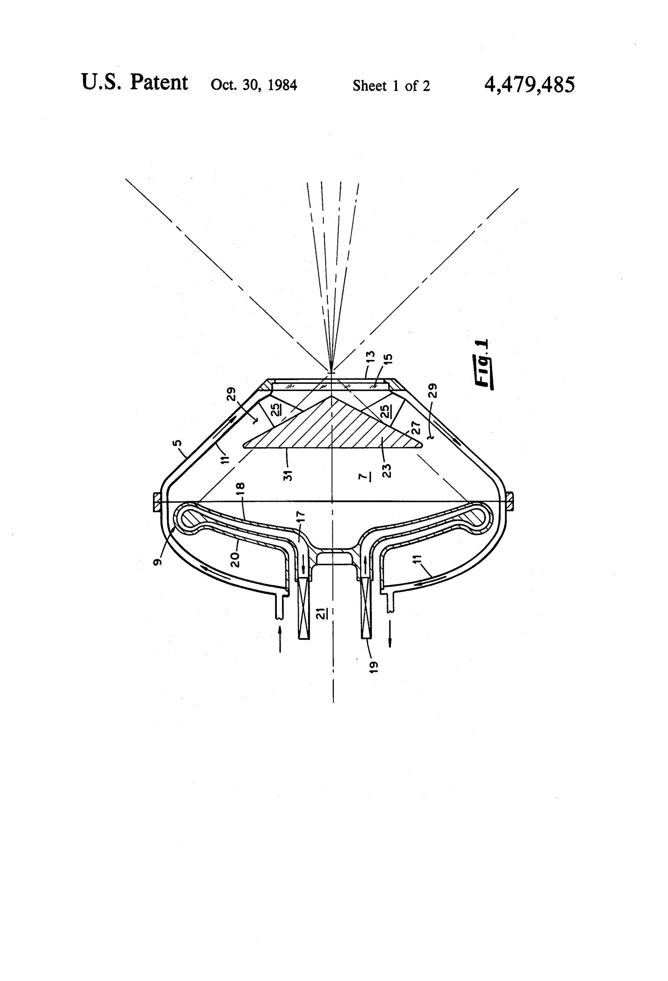
The invention was made as a result of a contract with aforementioned internal surface. the United States Department of Energy. BRIEF DESCRIPTION OF THE DRAWINGS BACKGROUND OF THE INVENTION FIG. 1 is a schematic side view, partly in section, of This invention relates generally to an apparatus for 10 a solar power cavity receiver designed in accordance absorbing solar power, and more particularly, to solar with the invention, ovens, solar cells for testing materials at high tempera FIG. 2 is a ray diagram for another receiver designed tures, and other solar power receivers of the cavity in accordance with the invention, the receiver being type. shown in a fragmentary schematic side view. This invention was an outgrowth of research directed 15 DETALED DESCRIPTION OF THE toward development of a solar cavity receiver such as a INVENTION test cell, for testing the performance of various materi als attemperatures on the order of 3000' F. Operation at Our invention is applicable to solar receivers in gen such temperatures may be a requirement for compo eral. For brevity, it will be illustated below in terms of nents of large-scale systems for utilizing solar thermal 20 an improved solar receiver of the cavity type. energy. Referring again to FIG. 1, the above-described re Referring to FIG. 1, initially the solar cavity receiver ceiver is shown as modified in accordance with the consisted of two major components: (a) a housing 5 and invention. A generally cone-shaped opaque baffle 23 is (b) a photothermal absorber 9, or heat exchanger, posi mounted coaxially in cavity 7 of the aforementioned tioned within the cavity. As shown, the housing defined 25 housing 5 and is rigidly supported therein by plates 25. a coaxial inlet 13 in which a window 15 was mounted Preferably, the baffle is cooled by circulating a fluid for transmission of a concentrated solar beam into the through passageways (not shown) in the baffle and cavity and onto the absorber. As shown, absorber 9 plates. The front surface 27 of the baffle has a reflective could be a generally dish-shaped member formed with finish and defines a relatively narrow annulus 29 with an internal passage 17 for circulation of a heat-transfer 30 the reflective interior 11 of the housing. The back sur fluid through a heat exchanger 19. face 31 of the baffle is also reflective and confronts the After consideration of the above-described receiver, front surface of the absorber 9.
we concluded that significant power losses would occur The baffle 23 is positioned so that its front surface 27 because part of the incoming solar power would be intercepts most of the radiation entering the cavity 7. radiated back through window 15. That is, part of the 35 The reflective front surface is contoured to direct the incoming rays would be reflected back through the intercepted radiation onto the front face 18 of the ab window and part of the infrared radiation generated by sorber 9 via single reflection off the interior surface 11 the heated absorber 9 would be radiated through the of the housing. That is, the front surface of the baffle is window. These power losses would appreciably limit designed to direct the incoming rays to the surface 11 the maximum temperature attainable in the cavity and thence, through the annulus 29, to the front surface which, as in this case, could be used as a test cell, or as of the absorber. The back surface 31 of the baffle is a thermochemical process vessel, a heat source for a designed to intercept most of the infrared radiation thermodynamic cycle engine, etc. emitted from the front surface 18 of the absorber and to
SUMMARY OF THE INVENTION
direct it generally obliquely back to the absorber. Thus, 45 the confronting surfaces 18 and 31 effect absorption of
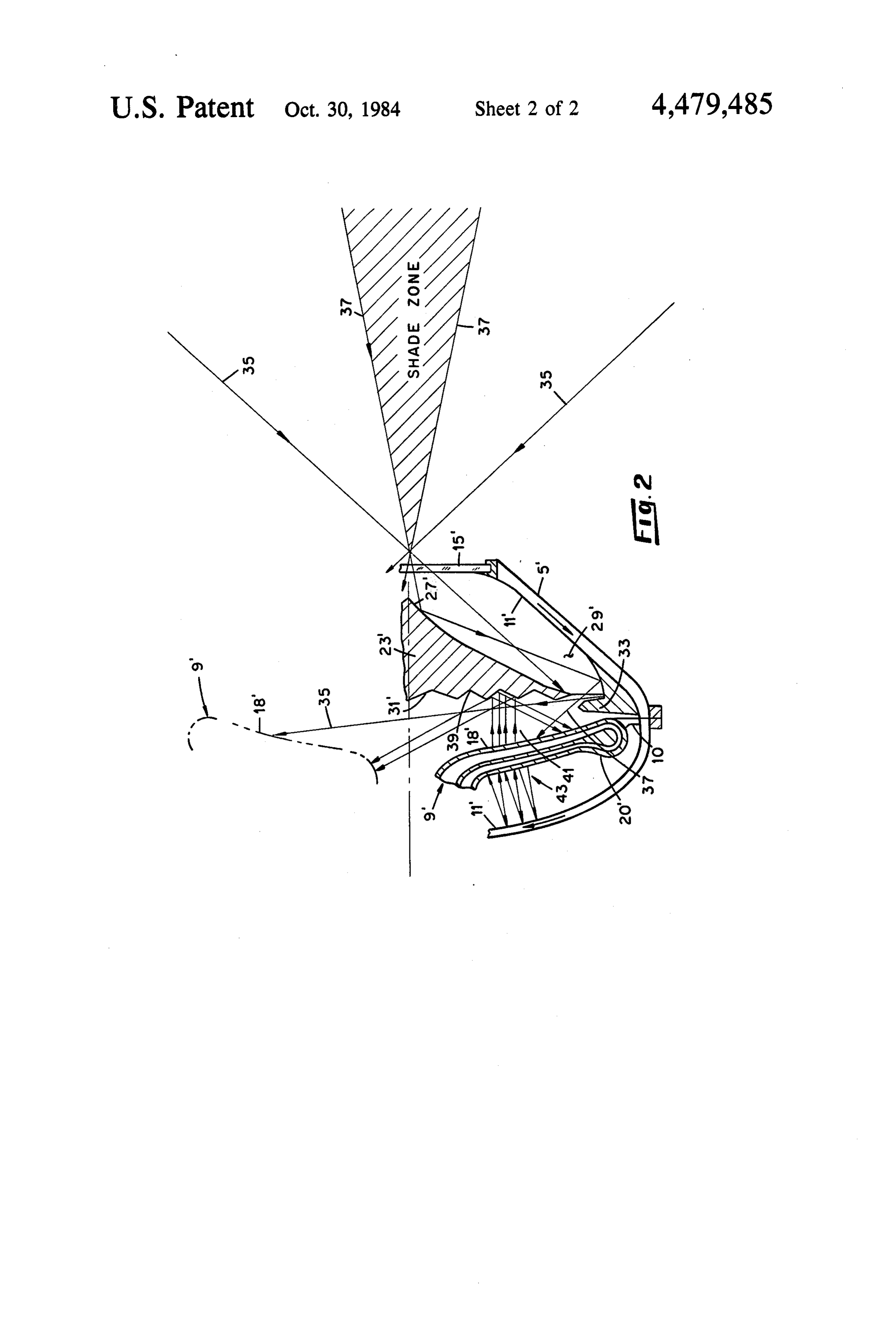
Accordingly, it is an object of this invention to pro most of the infrared radiation emitted from the front of vide an improved solar power absorption apparatus. the absorber. Being positioned as shown, the baffle 23 It is another object to provide a solar power receiver also blocks the escape of visible radiation which is re of a novel design with a higher maximum temperature flected in the direction of the window by the interior capability. 50 surface 11 of the housing. Infrared radiation emitted by It is another object to provide a solar power receiver the back surface 20 of the absorber is reflected back to of the cavity type, the receiver being designed to maxi surface 20 by the adjacent surface 11 of the housing. mize the retention of solar generated heat in the re Thus, the various reflective surfaces of the improved ceiver. cavity receiver cooperatively effect retention of a high It is another object to provide a solar power receiver 55 percentage of the solar power entering the receiver. of the cavity type, the receiver being designed to maxi FIG. 2 is a ray diagram for an improved solar cavity mize utilization of the solar power input thereto. receiver which is generally similar to the receiver Other objects and advantages will be made evident shown in FIG. 1. The receiver shown in FIG. 2 in hereinafter. cludes the following components, which function simi In one aspect, the invention is an apparatus for ab larly to those previously described: a housing 5' com sorbing solar power. The apparatus comprises a solar posed of a suitable material such as aluminum or graph radiation receiver which has a cavity with an internal ite and including a highly reflective surface 11’ and a reflective surface. The receiver also includes an inlet for pressure window 15' composed of a suitable material transmitting solar radiation into the cavity. An absorber such as fused silica or sapphire, for sealing the cavity; a for solar radiaton is mounted in the cavity. Mounted 65 refractory (e.g., SiC) absorber 9' mounted on supports between the absorber and the inlet is a baffle which has 10, one of which is shown; and a baffle 23' made of a a reflective back surface confronting the absorber. The suitable material such as stainless steel having a highly baffle has a reflective front surface which defines, with reflective front surface 27" of low solar ray absorptance,
Page 5
such as silver plating, and a back surface 31' of low 1. Apparatus for absorbing a beam of concentrated infrared absorptance such as gold plating, the latter solar power for utilization comprising: surface being configured to promote diffuse reflection a cavity receiver having internal reflective surfaces of radiation received from the absorber and typically and an inlet for transmission of solar radiation into comprising a concentric series of V-grooves 39. the cavity;
As shown, the housing is formed with an internal ring a radiation absorber having front and back surfaces portion 33 which extends toward the edge of the baffle. mounted within the cavity;
The forward face of the ring portion has the same sur a baffle provided with front and back reflective sur face finish as surface 11" and the rearward face has the faces;
same surface finish as surface 31' to restrict escape of 10 means for mounting said baffle within said cavity radiation from surface 18'. between said front surface of said absorber and said Although in the embodiment shown, the configura inlet enabling said front surface of said baffle to tion of front surface 27" and internal surface 11" appear intercept directly substantially all of the radiation concave, this is not essential. In all applications those entering the cavity and reflect said radiation to said surfaces are so configured that their coaction directs 15 absorber via secondary reflection from the internal impinging rays for eventual absorptance within the surfaces of the cavity and enabling said back sur cavity. face of said baffle to intercept substantially all of Still referring to FIG. 2, the solar flux entering the the infrared radiation emitted from the front sur window 15' is received from any suitable solar source, 20 face of the absorber.
such as a conventional paraboloidal dish-shaped mirror back The 2. apparatus of claim 1 in which the reflective surface of the baffle has a low infrared radiation concentrator (not shown). In FIG. 2, the beam bundle absorptance.
received from the concentrator is characterized by a central shade zone; this feature is not essential to attain front 3. The apparatus of claim 1 in which the reflective surface of the baffle has a low solar radiation ment of the objectives of the invention. Referring to the 25 absorptance.
beam bundle, its outermost rays 35, its innermost rays 4. The apparatus of claim 1 in which the inlet to the 37, and the rays therebetween pass through the window cavity receiver is enclosed by a window of a material and are intercepted by the front surface 27" of the baffle. such as fused silica or sapphire for containing a gaseous As indicated, the intercepted rays are reflected from atmosphere within the cavity. surface 27" to surface 11", which reflects them through 30 5. The apparatus the annulus 29' and onto various portions of the front generally in the shapeofofclaim 1 in which the baffle is a cone, said back surface being surface 18' of the absorber 9'. the base of said cone.
As shown in FIG. 2, infrared radiation 41 emitted by 6. The apparatus of claim 1 in which the front surface the surface 18' of the absorber is reflected back to the of the baffle is the conical surface of the cone. absorber by the rear face 31' of the baffle. Infrared 35 7. The apparatus of claim 1 in which the back surface radiation 43 emitted by the back face 20' of the absorber is reflected back to that face by the adjacent surface 11" of the baffle is configured to promote diffuse reflection of infrared radiation received from the absorber com of the housing. prising mechanical contouring such as a concentric The foregoing description of the invention has been series of V-grooves.
presented to explain the principles of the invention and 8. The apparatus of claim 1 in which an annular pro to illustrate its application to solar cavity receivers. The jection within the cavity projects toward the baffle to description is not intended to be exhaustive or to limit restrict escape of radiation from the absorber, said pro the invention to the particular embodiments disclosed. jection having a forward face which has a low solar Obviously, many modifications and variations are possi radiation absorptance and a rearward face which has a ble in light of the above teachings. For instance, various 45 low infrared radiation absorptance. reflective surface platings or coatings may be utilized to 9. Apparatus for absorbing a beam of concentrated attain the purposes of the invention. Given the teaching solar power for utilization, including a cavity receiver herein, one skilled in the art can determine the most having an inlet for transmission of solar radiation into suitable contours for the reflective surfaces for a partic the cavity, a radiation absorber within the cavity, and in ular application, without resorting to more than routine 50 which said cavity is provided with internal reflective calculation or experimentation. The absorber (9, FIG. surfaces, and a radiation trap positioned within the cav 1) may be any suitable device for absorbing solar radia ity between the inlet and the absorber adjacent said inlet tion and may have various configurations. The window to intercept directly substantially all of the solar radia (15, FIG. 1) is not required for all applications, but is tion transmitted through said inlet, said trap having a used where a pressurized heat-transfer fluid is circu 55 surface of low solar radiation absorptance and which lated through the cavity. Preferably, the above-men reflects impinging rays toward the internal reflective tioned baffle is designed to intercept virtually all of the surfaces of the cavity for directing the same toward the rays entering the cavity. absorber, and in which said trap has a back surface It is intended that the scope of the invention be de confronting the absorber, said back surface being of low fined by the appended claims. 60 infrared radiation absorptance. What is claimed is: k x 2k x x
Provenance
- Collection
- Patents citing this work
- Pages
- 5
- Method
- pdftotext (the PDF's own text layer) + pdftoppm 300dpi page scans
- Patent office record
- patents.google.com →
- Source
- Google Patents citing-documents table
- Assignee
- The United States Of America As Represented By The United States Department Of Energy
- Published
- 1984-10-30
- Transcribed from
- patentimages.storage.googleapis.com →