patent · US4263895
Solar energy receiver
28 April 1981
Page 1 — bibliographic record
United States Patent (19) 11) 4,263,895 Colao 45) Apr. 28, 1981 (54) SOLAR ENERGY RECEIVER Car. Press, (C)1974, "Non-Electronic Applications of SiC' by P. Shaffer, p. 349.
(75) Inventor: Angelo A. Colao, Bedford, Mass. Primary Examiner-Carroll B. Dority, Jr. 73 Assignee: Sanders Associates, Inc., Nashua, Assistant Examiner-Lee E. Barrett N.H. Attorney, Agent, or Firm-Louis Etlinger; Richard I. Seligman (21) Appl. No.: 842,704 57 ABSTRACT 22 Filed: Oct. 17, 1977 A highly efficient, open-ended solar energy receiver is disclosed having a porous element through which air 51) int. Cl.................................................. F24J 3/02 passes and a conventional heat exchanger positioned 52 U.S.C. .................................... 126/438; 126/450; above and immediately adjacent to the porous element 126/452; 60/641 such that when solar energy is focused onto the porous 58) Field of Search ............... 126/432, 435, 438, 452, element, a constant controlled temperature hot air 126/440, 449, 424; 60/641, 439 stream from the element is conveyed by the tempera ture controlled convectively rising hot air to the con (56) References Cited ventional heat exchanger to produce steam, thereby
flowing through the receiver is regulated, if desired, by 2,998,005 8/1961 Johnston .............................. 126/270 a low-power exhaust fan operating at a relatively low 3,203,167 8/1965 Green ..................................... 60/64 temperature due to the removal of heat by the heat 3,924,604 12/1975 Anderson ............................. 126/438 exchanger. Regulation may also be obtained by an 3,927,659 12/1975 Blake .................................... 126/271 3,979,597 9/1976 Drucker ............................... 126/439 opening at the top of the receiver, controlled in such a 3,993,041 11/1976 Diggs ................................... 126/440 manner as to vary the air flow through the system to 4,047,517 9/1977 Arnberg............................... 126/270. maintain a constant temperature output from the heat 4,121,564 10/1978 Schwartz ............................. 126/450 exchanger. Additionally, if desired, water flow control OTHER PUBLICATIONS may be utilized to maintain the proper energy balance. Silicon Carbide-1973, ed. by Marshall, et al., Univ. of S. 16 Claims, 2 Drawing Figures
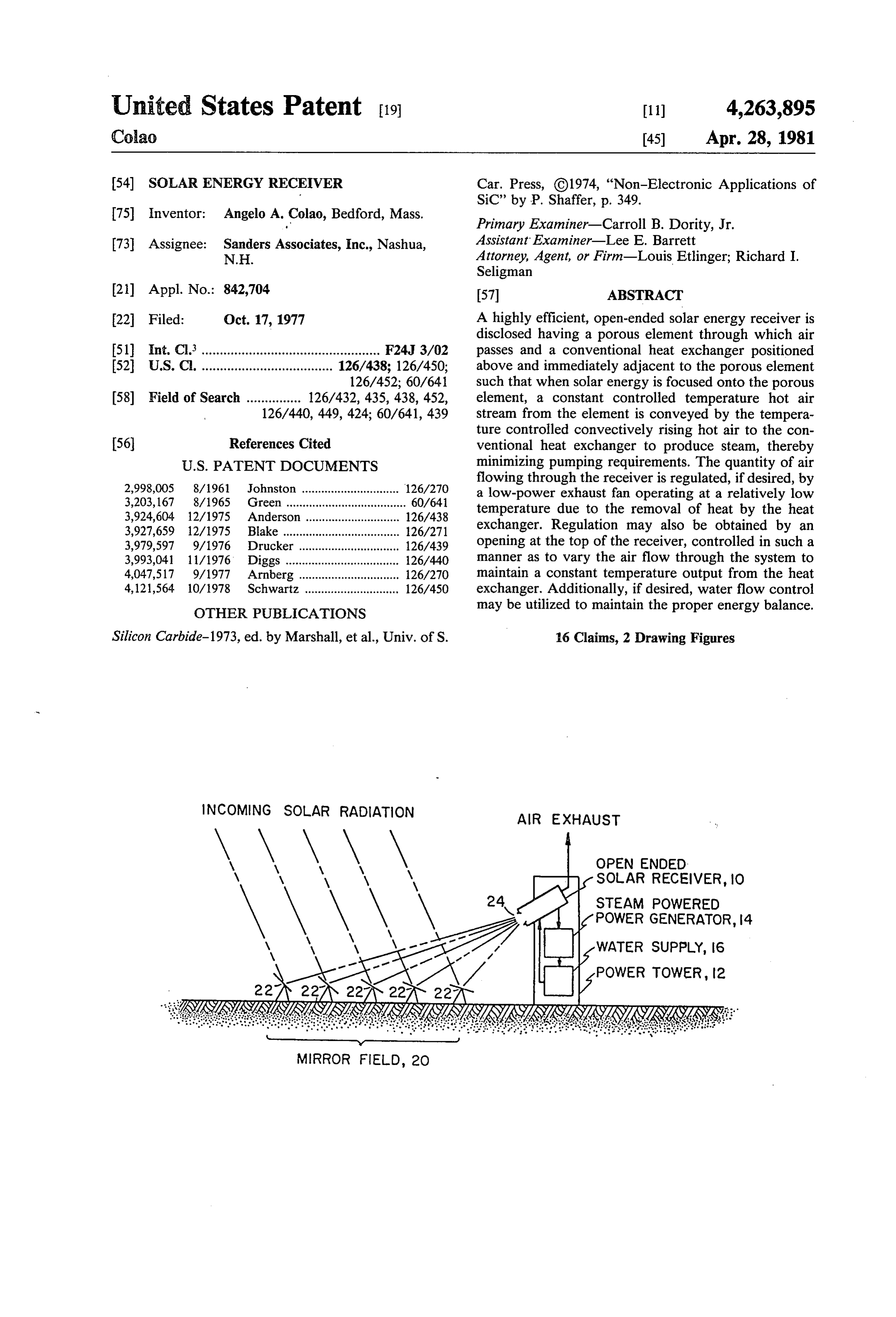
NCOMING SOLAR RADATION AIR EXHAUST
OPEN ENDED
SOLAR RECEIVER, O
STEAM POWERED
POWER GENERATOR, 4
WATER SUPPLY, 6
POWER TOWER 12
MIRROR FIELD, 2O
Page 2
NCOMING SOLAR RADATION AR EXHAUST
\ \, \\ \y \\, \\, OPEN ENDED
SOLAR RECEIVER, IO
STEAM POWERED
POWER GENERATOR, 4
WATER SUPPLY, 16
MIRROR FIELD, 2O
CONVECTIVELY
RSING HOT AR
WATER N
SOLAR ENERGY IN
Page 3
SOLAR ENERGY RECEIVER as exemplified by this patent, the use of convection as the means of transferring solar energy was avoided and
FIELD OF INVENTION was generally thought to be a serious defect. This invention relates to solar receivers and more Contrary to the teaching of this patent, it has been particularly to openended solar receivers adapted for found that by the utilization of the open ended concept, steam generation in which solar energy is first utilized along with a heat exchanger above a porous body, to heat a solar absorber in the form of a porous member transfer of energy be convection is, in fact, more effi adjacent to a conventional 'steam boiler or like heat cient and, therefore, rather than being avoided is, in exchanger located above the porous member. fact, sought. The efficiency increase comes from mini 10 mizing the pumping energy which is utilized in either
BACKGROUND OF THE INVENTION one of the two above-mentioned patents and by the As illustrated in U.S. Pat. No. 3,924,604 issued to proximity of the boiler to the heated porous body. Donald E. Anderson, on Dec. 9, 1975, it is known to One purpose of providing the porous solar absorber is provide a solar energy receiver on the top of a mast, 15 to provide a controlled temperature fluid (air) as the below which is provided a mirror field which includes a heat exchange medium. This prevents high temperature number of mirrors which redirect incoming solar radi areas from occurring on the heat exchanger due to solar ation and focus it onto the solar receiver. In this patent energy distribution non-uniformities if the heat ex ingested air is pumped from the top of the tower to the changer were to be heated directly by the focused solar bottom of the tower and thence to a boiler which radiation. It should be noted that solar radiation distri provides a mechanism for transferring the focused solar 20 butions have been measured to vary by as much as 10:1, energy into usable energy by virtue of fluid heated in the which could burn out a directly illuminated heat ex boiler.
One of the outstanding problems in this type system is changer. Further, a loss of coolant (water) with a direct solar impingement heat exchanger would result in very the necessity of pumping the air from the receiver down high temperature and a burnout or meltdown. In con through the tower to a subsurface boiler, which pump 25 trast, in the embodiment presented, there is a maximum ing energy is considerable.
In the Anderson patent it is further noted that louvers upper limitupper controlled
limit to the air temperature, and this provided by the solar absorber. This, in are heated by focused solar radiation. The heating of turn, prevents heat exchanger failure or requirement for louvers is, to a certain extent, inefficient when coupled repair.
with the amount of flow necessary to remove the heat 30 from the louvers and then transfer this energy down to an Itefficient is, therefore, the object of this invention to provide the base of the tower which may be on the order of minimized; solar receiver in which pumping energy is several hundred feet high.
In the subject invention the heat exchanger, rather It istemperature another object of this invention to provide constant solar heated air to a heat exchanger re than being located at some distance from the point at 35 gardless of solar density variations, thereby to pre which solar radiation is focused, is placed above a po vent damage to the heat exchanger. rous high-temperature absorbing material at or near the focus of the solar radiation. The receiver in one embodi It is another object of this invention to provide the ment is an open-ended device which includes a cavity combination of an openended solar receiver utilizing having an opening and a porous body member or ele 40 a porous member and a closely spaced heat ex ment positioned at or near the opening. Heat from the changer which receives the majority of its energy porous body is transmitted to a conventional steam-type through flow caused by convection; heat exchanger which is positioned above and adjacent It is still further object of this invention to locate a heat to the porous body primarily by virtue of the convec exchanger above a porous body heated by focused tively-rising hot air. In one embodiment, temperature 45 solar radiation in which the energy from the focused control is obtained by regulation of an exhaust fan, solar radiation is transferred to the heat exchanger via while in another embodiment control is obtained by a convective currents. These and other objects will be variable orifice at the top of the receiver. When an better understood in connection with the following exhaust fan is used, pumping energy expended by the specifications when taken in conjunction with the exhaust fan utilized is minimal because of the convec 50 following drawings.
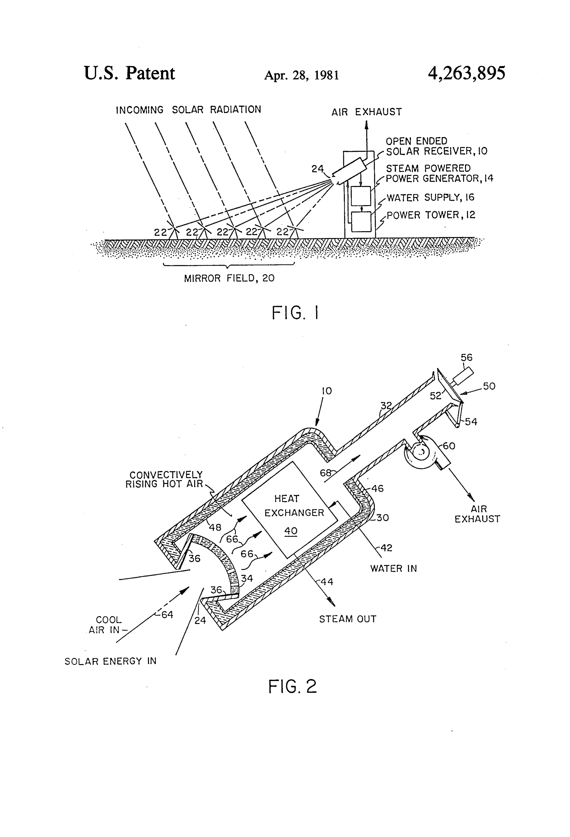
tively rising hot air and the particular position of the BRIEF DESCRIPTION OF THE DRAWINGS heat exchanger above the heated porous body.
Other types of steam generating plants employing a FIG. 1 illustrates diagrammatically a conventional receiver mounted on a tower are exemplified by U.S. power tower/mirror field combination illustrating the Pat. No. 3,927,659 issued to Floyd A. Blake et all on 55 placement of the subject open-ended solar receiver; and Dec. 23, 1975, in which a closed receiver having a win FIG. 2 is a cross-sectional and diagrammatic illustra dow employs heat exchanger tubes within the body of tion of the subject solar energy receiver. the receiver to convert the solar energy into steam.
Here no porous member is employed. However, it is DETAILED DESCRIPTION notable that in this patent at column 1, lines 38 through Referring now to FIG. 1, an open-ended receiver 10 43, it is said that "convection problems have been mini is mounted in a power tower 12 which may also house mized to some extent by locating the boiler superheater a steam powered generator 14 and water supply/pump units above the reflection mirror field with the cavity or unit 16. Alternatively, any fluid may be used. Adjacent conversion chamber at the bottom of the unit and facing to power tower is a mirror field 20 containing individu vertically the mirror field, and while this trapped, to 65 ally steerable mirror elements 22 which redirect incom some extent, hot air from convection in the chamber, ing solar radiation through the aperture 24 of the open this adversely limits the physical plant and results only ended solar receiver. The aperture may be smaller in in minimizing to some degree convection losses.' Thus, diameter than the body of the receiver so that energy
Page 4
radiated back towards the aperture is reflected back vection process and that this is a major feature of the into the receiver cavity. It is the purpose of this arrange subject invention.
ment to heat the water from the water supply so as to The configuration of heat exchanger 40 at least in supply steam to a steam-powered generator in the most principle is not critical to the subject invention and may efficient manner possible. As mentioned hereinbefore, be any one of a number of type of conventional boilers. this is done through convectively rising hot air as will Since the air temperature to the heat exchanger is made now be described in connection with one embodiment constant and controllable by the solar absorber, heat of the subject invention shown in FIG. 2. exchanger design is considerably simplified. The cooler In FIG. 2 receiver 10 is shown to include a body air which exits the heat exchanger is illustrated by portion 30 and a stack portion 32. Located at or adja 10 arrow 68 and its flow is governed either via the variable cent aperture 24 is a solar absorber in the form of a aperture at the end of the stack or by the exhaust fan porous member 34 which may be made of silicon car which, it will be appreciated, need not be subjected to bide or the like. The porous member may be in the form extremely high temperatures and, therefore, may be of a of a bowed honeycomb in which the passages generally low-cost variety.
point towards the heat exchanger to be described here 15 What has, therefore, been provided is an extremely inafter. This directs a hot air flow caused by convection efficient low-cost solar energy receiver in which con- . to impinge on the heat exchanger. The porous member vectively rising hot air is utilized as the transfer medium is supported by supports 36 such that focused solar for transferring energy from focused sunlight to a fluid energy impinges on the porous member to heat it. The in the heat exchanger. Due to the proximity of the heat porous member may be in general any ceramic material 20 exchanger to the porous member and due to its location capable of withstanding the temperature involved with thereabove, problems of convectively lost energy men focused solar radiation with the position of the porous tioned hereinbefore are alleviated and are put to advan member not being particularly critical. The porous tage rather than being viewed as a detriment to the member provides a constant temperature air stream system. Moreover, heat exchanger burnout is prevented regardless of solar density variations and the tempera 25 by use of the solar absorber and its design is simplified. ture of this air can be made to vary by variation in the Although a preferred embodiment of the invention design of the porous member. has been described in considerable detail for illustrative Located adjacent to the porous member and there purposes, many modifications will occur to those skilled above is a heat exchanger 40 which may be any type of in the art, which modifications are within the spirit of conventional boiler. The flow of convectively rising 30 the invention. It is, therefore, desired that the protection hot air which has been heated by virtue of contact with afforded by Letters Patent be limited only by the true the porous member transfers constant temperature en scope of the appended claims.
ergy from the focused sunlight onto the heat exchanger I claim:
from whence it is utilized to convert water brought in 1. A solar energy receiver for use with focused solar on line 42 to steam. The output of the heat exchanger is 35 energy, comprising:
shown at line 44. a body having an opening at one end through which The body of the heat exchanger may be insulated by focused solar radiation is adapted to pass, and ex insulation shown generally at 46. An interior metallic or haust means at the opposite end thereof, other liner 48 may be provided as shown such that the a porous member capable of withstanding said fo majority of the energy focused into the receiver at its cused radiation, means for mounting said porous open end is captured and utilized to heat the fluid in the member adjacent the opening of said body, heat exchanger. It will be appreciated also that the fluid a heat exchanger means, and need not be limited to water but may be either air or means for mounting said heat exchanger means be other types of fluid or liquid. tween said porous member and said exhaust means In one embodiment the stack 32 may be provided 45 above and proximate to said porous member such with a variable orifice generally indicated at 50 which that energy is transferred to said heat exchange may include a cap 52 secured via a hinged arrangement means by convectively rising hot air. generally shown at 54 and operated via solenoid 56 as 2. The receiver of claim 1 wherein said exhaust means desired to control the convective flow through the includes means for controlling exhaust air thereby to stack and thus the heat balance of the entire system. 50 control the energy balance of the system. Alternatively or in conjunction therewith, an exhaust 3. The receiver of claim 2 wherein said control means fan generally indicated at 60 may be utilized to control includes variable orifice means.
the flow of the cooler air from the heat exchanger with 4. The receiver of claim 2 wherein said control means very little energy being expended by virtue of the ex includes exhaust fan means.
haust fan's operation. For further heat balance control, 55 5. The receiver of claim 1 wherein said porous mem the flow of fluid to the heat exchanger may also be ber is made of silicon carbide.
controlled. 6. The receiver of claim 1 wherein said porous mem Of course, the exhaust fan may be omitted and is used ber has a honeycomb structure in which the channels of herein only for maintaining the proper energy balance the honeycomb point in the direction of said heat ex within heat exchanger 40. changer means.
In operation, cool air generally indicated by arrow 64 7. The receiver of claim 1 and further including fluid is drawn through porous member 34 due to the convec storage means including means for pumping fluid in said tive process in which the hot air in the vicinity of the fluid storage means to said heat exchanger means, and porous member rises as illustrated by arrows 66. This power generating means coupled to said heat exchanger convective rising provides a flow of low velocity 65 means and run by the fluid heated by said heat ex through the heat exchanger and is utilized to heat the changer means.
fluid passing through the heat exchanger. It should be 8. The receiver of claim 1 and further including a noted that no air pumping is necessary due to the con mirror field and means for mounting said receiver
Page 5
above said mirror field such that said heat exchanger through said heat exchanger means and power generat means is above said porous member. ing means coupled to the output of said heat exchanger 9. A solar energy conversion system comprising: means for utilizing the heated fluid therefrom to gener means for focusing solar energy to a predetermined ate power.
location, 5 15. A method of preventing heat exchanger burnout an open-end receiver at said predetermined location, for heat exchangers which obtain energy from focused said open-ended receiver having exhaust means at solar energy comprising the steps of:
the end opposite said open-end, a porous member providing an open-ended solar receiver body having at said open end positioned to receive energy fo an outlet port opposite the open end with a heat cused through said open end, heat exchanger 10 exchanger located therein, and means proximate to and above said porous member positioning a porous solar energy absorber below the such that energy from said porous member is trans heat exchanger and between the open end and the ferrred convectively to said heat exchanger means, heat exchanger to intercept all of said focused solar and means for mounting said receiver such that energy, whereby constant temperature heated air is said focused solar energy impinges on said porous 15 convectively transferred to the heat exchanger member and such that said heat exchanger means is thereby to prevent burnout.
above said porous member. 16. A method of providing constant temperature 10. The system of claim 9 wherein said exhaust means solar heated hot air to a heat exchanger which obtains includes means for controlling convectively flowing energy from focused solar energy comprising the steps a1. 20 of:
11. The system of claim 9 wherein said porous mem providing an open-ended solar receiver body having ber has a honeycomb structure. an outlet port opposite the open end with a heat 12. The system of claim 11 wherein the channels of exchanger located therein, and said honeycomb point towards said heat exchanger positioning a porous solar energy absorber below the leaS. 25 heat exchanger and between the open end and the 13. The system of claim 9 wherein said porous mem heat exchanger to intercept all of said focused solar ber is made from silicon carbide. energy, whereby constant temperature heated air is 14. The system of claim 9 and further including a convectively transferred tok the heat exchanger. source of fluid including means for pumping said fluid ck k k sk
Provenance
- Collection
- Cited prior art
- Original PDF
- patentimages.storage.googleapis.com →
- Filed
- 1977-10-17
- Pages
- 5
- Method
- pdftotext (the PDF's own text layer) + pdftoppm 300dpi page scans
- Source
- Google Patents bibliographic record
- Granted
- 1981-04-28
- Inventors
- Angelo A. Colao; Sanders Associates Inc
- Transcribed from
- patentimages.storage.googleapis.com →